EP0863226A1 - Halter mit modularem Aufbau für Beschichtungsanlage - Google Patents
Halter mit modularem Aufbau für Beschichtungsanlage Download PDFInfo
- Publication number
- EP0863226A1 EP0863226A1 EP97117928A EP97117928A EP0863226A1 EP 0863226 A1 EP0863226 A1 EP 0863226A1 EP 97117928 A EP97117928 A EP 97117928A EP 97117928 A EP97117928 A EP 97117928A EP 0863226 A1 EP0863226 A1 EP 0863226A1
- Authority
- EP
- European Patent Office
- Prior art keywords
- workpiece
- fixture
- coating
- workpieces
- opposed
- Prior art date
- Legal status (The legal status is an assumption and is not a legal conclusion. Google has not performed a legal analysis and makes no representation as to the accuracy of the status listed.)
- Granted
Links
- 238000000576 coating method Methods 0.000 title claims abstract description 65
- 239000011248 coating agent Substances 0.000 title claims abstract description 64
- 239000000463 material Substances 0.000 claims abstract description 21
- 238000000034 method Methods 0.000 claims abstract description 19
- 230000000873 masking effect Effects 0.000 claims description 5
- 230000013011 mating Effects 0.000 claims description 5
- 238000005328 electron beam physical vapour deposition Methods 0.000 description 3
- 238000003466 welding Methods 0.000 description 2
- 238000010960 commercial process Methods 0.000 description 1
- 238000010276 construction Methods 0.000 description 1
- 238000005260 corrosion Methods 0.000 description 1
- 230000007797 corrosion Effects 0.000 description 1
- 230000005484 gravity Effects 0.000 description 1
- 238000009434 installation Methods 0.000 description 1
- 238000012423 maintenance Methods 0.000 description 1
Images


Classifications
-
- C—CHEMISTRY; METALLURGY
- C23—COATING METALLIC MATERIAL; COATING MATERIAL WITH METALLIC MATERIAL; CHEMICAL SURFACE TREATMENT; DIFFUSION TREATMENT OF METALLIC MATERIAL; COATING BY VACUUM EVAPORATION, BY SPUTTERING, BY ION IMPLANTATION OR BY CHEMICAL VAPOUR DEPOSITION, IN GENERAL; INHIBITING CORROSION OF METALLIC MATERIAL OR INCRUSTATION IN GENERAL
- C23C—COATING METALLIC MATERIAL; COATING MATERIAL WITH METALLIC MATERIAL; SURFACE TREATMENT OF METALLIC MATERIAL BY DIFFUSION INTO THE SURFACE, BY CHEMICAL CONVERSION OR SUBSTITUTION; COATING BY VACUUM EVAPORATION, BY SPUTTERING, BY ION IMPLANTATION OR BY CHEMICAL VAPOUR DEPOSITION, IN GENERAL
- C23C14/00—Coating by vacuum evaporation, by sputtering or by ion implantation of the coating forming material
- C23C14/22—Coating by vacuum evaporation, by sputtering or by ion implantation of the coating forming material characterised by the process of coating
- C23C14/50—Substrate holders
-
- C—CHEMISTRY; METALLURGY
- C23—COATING METALLIC MATERIAL; COATING MATERIAL WITH METALLIC MATERIAL; CHEMICAL SURFACE TREATMENT; DIFFUSION TREATMENT OF METALLIC MATERIAL; COATING BY VACUUM EVAPORATION, BY SPUTTERING, BY ION IMPLANTATION OR BY CHEMICAL VAPOUR DEPOSITION, IN GENERAL; INHIBITING CORROSION OF METALLIC MATERIAL OR INCRUSTATION IN GENERAL
- C23C—COATING METALLIC MATERIAL; COATING MATERIAL WITH METALLIC MATERIAL; SURFACE TREATMENT OF METALLIC MATERIAL BY DIFFUSION INTO THE SURFACE, BY CHEMICAL CONVERSION OR SUBSTITUTION; COATING BY VACUUM EVAPORATION, BY SPUTTERING, BY ION IMPLANTATION OR BY CHEMICAL VAPOUR DEPOSITION, IN GENERAL
- C23C14/00—Coating by vacuum evaporation, by sputtering or by ion implantation of the coating forming material
- C23C14/04—Coating on selected surface areas, e.g. using masks
- C23C14/042—Coating on selected surface areas, e.g. using masks using masks
-
- C—CHEMISTRY; METALLURGY
- C23—COATING METALLIC MATERIAL; COATING MATERIAL WITH METALLIC MATERIAL; CHEMICAL SURFACE TREATMENT; DIFFUSION TREATMENT OF METALLIC MATERIAL; COATING BY VACUUM EVAPORATION, BY SPUTTERING, BY ION IMPLANTATION OR BY CHEMICAL VAPOUR DEPOSITION, IN GENERAL; INHIBITING CORROSION OF METALLIC MATERIAL OR INCRUSTATION IN GENERAL
- C23C—COATING METALLIC MATERIAL; COATING MATERIAL WITH METALLIC MATERIAL; SURFACE TREATMENT OF METALLIC MATERIAL BY DIFFUSION INTO THE SURFACE, BY CHEMICAL CONVERSION OR SUBSTITUTION; COATING BY VACUUM EVAPORATION, BY SPUTTERING, BY ION IMPLANTATION OR BY CHEMICAL VAPOUR DEPOSITION, IN GENERAL
- C23C14/00—Coating by vacuum evaporation, by sputtering or by ion implantation of the coating forming material
- C23C14/22—Coating by vacuum evaporation, by sputtering or by ion implantation of the coating forming material characterised by the process of coating
- C23C14/50—Substrate holders
- C23C14/505—Substrate holders for rotation of the substrates
Definitions
- the present invention relates to a novel modular fixture to be used in an apparatus for coating workpieces and to a process for coating said workpieces.
- the present invention has particular utility in the coating of vanes and blades for industrial turbines and jet engines.
- Vanes and blades used in industrial turbines and jet engines are typically subjected to a coating operation to improve their resistance to corrosion, thermal fatigue, and to otherwise enhance their performance. Economic concerns dictate that one must be able to simultaneously coat multiple workpieces in order to have a commercial process.
- U.S. Patent No. 4,192,253 One commercial system for simultaneously coating a plurality of workpieces is shown in U.S. Patent No. 4,192,253.
- a plurality of workpieces to be coated are inserted into a coating chamber and simultaneously rotated about their longitudinal axes during the coating operation.
- the simultaneous rotation of the workpieces about their longitudinal axes is accomplished by mounting each workpiece to the tip of a fixture whose other end is connected to a complex gear operated drive system for rotating the fixture and the individual workpieces mounted thereto.
- This type of system is disadvantageous for a number of reasons. For example, the system is complex and potentially troublesome from a maintenance standpoint. Still further, the costs associated with such a system are quite high. Yet, another disadvantage is the delay incurred in individually removing the coated workpieces from each of the fixtures and mounting new workpieces to be coated onto the fixtures.
- Certain coating techniques such as electron beam physical vapor deposition, are line of sight techniques wherein surfaces of a workpiece which are not in a line of sight with the source of the coating material will not be coated.
- an apparatus for coating one or more workpieces broadly comprises a modular fixture which includes a means for supporting each workpiece to be coated so as to cause each workpiece during the coating operation to simultaneously rotate about its longitudinal axis and tilt towards a source of coating material.
- the modular fixture includes a longitudinally extending shaft and at least one support plate attached thereto.
- the supporting means for each workpiece comprises a bushing arrangement within each support plate and a cooperating spindle arrangement to which the workpiece is attached.
- a plurality of bushing arrangements are radially spaced around each support plate and a cooperating spindle arrangement is provided for each bushing arrangement.
- the bushing arrangement preferably comprises a hollow cylindrical sleeve having an interior bore of a desired dimension whose interior surface has been roughened
- the spindle arrangement preferably comprises a pin having an enlarged end portion for contacting one end of the sleeve and a shaft portion attached to the enlarged end portion.
- the shaft portion has an outer diameter less than the diameter of the interior bore. This, together with the roughness of the bore, permits the workpiece attached to the spindle arrangement to be rotated about its longitudinal axis as the modular fixture is rotated about its longitudinal axis and simultaneously tilted relative to the longitudinal axis of the fixture and towards the source of the coating material.
- the process of the present invention as claimed broadly comprises the steps of providing a source of coating material; attaching a workpiece to be coated to a fixture; and coating at least one surface of said workpiece by rotating said fixture and said workpiece attached thereto and simultaneously tilting said workpiece toward the source of the coating material.
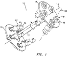
- FIG. 1 illustrates a modular coating fixture 10 in accordance with the present invention.
- the fixture 10 includes a central shaft 12 which extends in a direction parallel to the longitudinal axis 14 of the fixture 10.
- the fixture 10 further includes two spaced apart support plates 16 and 18 which are preferably welded to the shaft 12. If desired, the support plates 16 and 18 may be secured to the shaft 12 by a plurality of supports 20 welded to the shaft 12 at various locations about its periphery and welded to the support plates 16 and 18.
- the shaft 12 may be hollow to save weight.
- cylindrical mounting column 22 protrudes from one end of the fixture 10.
- the mounting column 22 may be an extension of shaft 12 or a separate component welded to one of the support plates 16 and 18.
- the mounting column 22 is hollow and designed to receive a mating portion 34 of a connecting member 24 affixed to a drive system (not shown) for rotating the fixture 10 about its longitudinal axis 14.
- the mounting column 22 is preferably provided with two aligned, opposed slots 26 and 28. Additionally, it has a keyway 30 adjacent one end thereof.
- the connecting member 24 includes a base portion 32 and a shaft portion 34 which is joined to the base portion 32 by a pivot 36. As shown in FIG. 4, the pivot 36 allows the shaft portion 34 to be moved relative to the base portion 32 so as to facilitate installation and removal of the fixture 10.
- the shaft portion 34 is dimensioned to fit within the hollow mounting column 22.
- the base portion 32 is provided with two slots 38 and 40 for mating with the slots 26 and 28 in the column 22. Furthermore, the base portion 32 has a key 42 which fits into the keyway 30 to ensure that the slots 38 and 40 are properly aligned with the slots 26 and 28.
- a wedge 44 is inserted through the slots 26, 38, 40 and 28.
- the wedge 44 preferably has an eyelet 46 adjacent one end for receiving a wire (not shown) to lock it in place.
- a plurality of bushings 48 are radially spaced about each of the support plates 16 and 18.
- the number of bushings 48 in each support plate and the spacing of the bushings 48 relative to the shaft 12 are determined by the type of workpiece or workpieces to be coated.
- the bushings 48 are formed by a hollow cylindrically shaped sleeve member 50 welded on two sides to the respective support plate 16 or 18.
- the interior bore 52 of the sleeve member may have any desired diameter. For reasons to be discussed hereinafter, the surfaces of the bore 52 are preferably roughened.
- the workpiece 54 being coated it is necessary for the workpiece 54 being coated, to rotate about its longitudinal axis 122 so that multiple surfaces of the workpiece, such as the leading edge 56 and the opposed flow surfaces 58 and 60 are substantially uniformly coated. It is also desirable in many applications for a surface 62 substantially perpendicular to the flow surfaces 58 and 60 to be coated as well.
- line of sight coating processes such as electron beam physical vapor deposition processes, it is necessary to tilt the workpiece 54 towards the source of coating material 120 as the workpiece 54 is rotated about its longitudinal axis 122 in order to coat the surface 62.
- the desired coating of the surface 62 is obtained by using a spindle arrangement 64 with each bushing 48 to tilt the workpiece towards the source of the coating material.
- the spindle arrangement 64 preferably comprises a pin 66 having a shaft portion 67 and an enlarged head portion 68, which head portion abuts against one end of the bushing 48 with which it is associated.
- the shaft portion 67 has a roughened surface and an exterior diameter which is smaller than the interior diameter of the bore 52 so as to allow the pin 66 to tilt relative to the bushing 48.
- the diameter of the shaft portion 67 along with the length of the sleeve 50 and the diameter of bore 52 determine the degree of tilt. Obviously, the degree of tilt must not be such that the workpiece 54 contacts the shaft 12 during coating.
- the pin 66 further includes a reduced shaft portion 69 which fits into a cup-shaped member 72 which will be described hereinafter.
- the workpiece 54 to be coated is attached to the spindle arrangement 64.
- the workpiece 54 is attached to the pin 66 via a workpiece retaining device 70 and a cup shaped member 72 attached to one end of the retaining device.
- the cup-shaped member 72 may be attached to the retaining device 70 by any suitable means known in the art such as by welding.
- the cup-shaped member 72 includes two opposed openings 74 and 76 for mating with a slot 78 in an end of the shaft portion 69.
- a pin or wedge-shaped member 80 is inserted through the opening 74, through the slot 78, and through the opening 76 to secure the cup-shaped member 72 to the pin 66.
- the pin or wedge-shaped member 80 is designed to securely affix the retaining device 70 to the spindle arrangement 64.
- the retaining device 70 is an open-faced and open-ended structure which includes a back wall 82 and two side walls 84 and 86 joined thereto.
- the retaining device 70 further includes a bottom wall 88 which connects the two side walls 84 and 86.
- the workpiece 54 to be coated is placed within the retaining device 70 via the open face defined by the side walls 84 and 86, the back wall 82 and the bottom wall 88. Once positioned within the retaining device 70, the portion of the workpiece 54 to be coated extends through the open end located opposite the bottom wall 88.
- the side walls 84 and 86 and the back wall 82 are shaped and/or configured to conform to the shape of the surface 62.
- the back wall 82 may be provided with a support plate 90 for holding the workpiece 54 in a desired position.
- the support plate 90 preferably cooperates with a feature on the workpiece 54 such as a ribbed portion or a notch (not shown), to hold it in the desired position.
- a masking device 92 may be mounted to the back wall 82 and/or to a side wall 84 to prevent certain portions of the workpiece 54, such as a trailing edge 94, from being coated.
- the masking device 92 may have any suitable shape and length. For example, it may be L-shaped. Of course, the shape of the masking device 92 will depend on the shape of that portion of the workpiece 54 not to be coated.
- a tongue member 96 is secured, such as by welding, to the interior side of side wall 84.
- the tongue member 96 has a slot 98 cut therein and serves to secure a cover 100 to the retaining device 70.
- the cover 100 has side portions 102 and 104 which overlap the side walls 84 and 86 when the cover is seated on the retaining device 70 and connecting portion 105 extending therebetween.
- the connecting portion 105 of the cover 100 includes a slot 106 through which the tongue member 96 protrudes.
- the connecting portion 105 of the cover 100 has an eyelet 108 attached to its exterior surface 110 and an optional support member 112 mounted to its interior surface 114. The support member 112 cooperates with a portion of the workpiece 54 to maintain the workpiece in a desired position within the retaining device 70.
- a wedge 116 is provided to secure the cover 100 to the retaining device 70. As shown in FIG. 8, the wedge 116 has a bore 118 adjacent one end thereof. When the wedge is placed into its securing position adjacent the exterior surface 110 of the cover, a wire (not shown) is passed through the bore 118 and the eyelet 108 so as to secure the wedge 116 in its proper position.
- FIG. 9 illustrates a workpiece secured within the retaining device 70.
- the various components of the modular fixture 10 such as the shaft 12, the support plates 16 and 18, the mounting column 22, the retaining device 70, the bushings 48, and the spindle arrangement 64 may be formed from any suitable material known in the art. Preferably, they are formed from a material known as HASTALLOY-X.
- the modular fixture 10 of the present invention is used in the following manner. First, a plurality of workpieces 54 to be coated are placed within the retaining devices 70. After the covers 100 have been secured in place, the modular fixture 10, with the workpieces 54 in place, is placed onto the connecting member 24 joined to a drive system (not shown). As previously described, the fixture 10 is secured to the connecting member 24 via the aligned slots 26, 28, 38 and 40 and the wedge 44 which passes through the slots. The fixture 10 after being secured to the connecting member 24 is transported into a coating chamber, such as an electron beam physical vapor deposition chamber, in which a coating material to be vaporized in a known manner is located. The actual technique for causing the coating material to be vaporized does not form part of the present invention. The fixture 10 may be used with any number of different techniques.
- the modular fixture 10 is rotated about its longitudinal axis 14 by the drive system (not shown).
- gravity and the presence of friction between each bushing and cooperating spindle arrangement causes each retaining device 70 and each workpiece 54 to rotate about the workpiece longitudinal axis 122 so that the opposed flow surfaces 58 and 60 and the leading edge 56 of each workpiece are coated.
- the bushing 48 and spindle arrangement 64 allow each workpiece 54 to tilt so that each of the axes 122 intersects the longitudinal axis 14 and towards the source of the coating material 120. As a result, those surfaces perpendicular to the flow surfaces 58 and 60, such as the platform surface 62, are exposed to the vaporized coating material and are also coated.
- the modular fixture 10 with the workpieces 54 is removed from the coating chamber and a new fixture 10 with new workpieces 54 to be coated is installed.
- the modular coating fixture of the present invention provides numerous commercial advantages. Most notably, the fixture allows the simultaneous coating of multiple workpieces. The fixture further allows easy placement of the workpieces therein and easy removal of the workpieces therefrom. Still further, the workpieces may be placed in the fixture and removed from the fixture while another set of workpieces are being coated on yet another fixture. Additionally, the fixture of the present invention is easier to use than prior art systems.
- the fixture of the present invention has particular utility in coating airfoils such as turbine blades and vanes.
- airfoils such as turbine blades and vanes.
- the fixture of the present invention is relatively simple in design when compared to expensive gear driven longitudinally and transverse act as part manipulation systems. Further, it can produce a close to uniform coating thickness and excellent coating structure. Due to the simplistic design of the fixture of the present invention, coating can be accomplished at a much lower cost.
Landscapes
- Chemical & Material Sciences (AREA)
- Chemical Kinetics & Catalysis (AREA)
- Engineering & Computer Science (AREA)
- Materials Engineering (AREA)
- Mechanical Engineering (AREA)
- Metallurgy (AREA)
- Organic Chemistry (AREA)
- Application Of Or Painting With Fluid Materials (AREA)
- Physical Vapour Deposition (AREA)
- Coating Apparatus (AREA)
- Spray Control Apparatus (AREA)
Applications Claiming Priority (2)
| Application Number | Priority Date | Filing Date | Title |
|---|---|---|---|
| US08/813,384 US6083322A (en) | 1997-03-06 | 1997-03-06 | Modular coating fixture |
| US813384 | 1997-03-06 |
Publications (2)
| Publication Number | Publication Date |
|---|---|
| EP0863226A1 true EP0863226A1 (de) | 1998-09-09 |
| EP0863226B1 EP0863226B1 (de) | 2001-12-19 |
Family
ID=25212224
Family Applications (1)
| Application Number | Title | Priority Date | Filing Date |
|---|---|---|---|
| EP97117928A Expired - Lifetime EP0863226B1 (de) | 1997-03-06 | 1997-10-16 | Modulare Halterung für Beschichtungen |
Country Status (5)
| Country | Link |
|---|---|
| US (1) | US6083322A (de) |
| EP (1) | EP0863226B1 (de) |
| JP (1) | JP3290620B2 (de) |
| DE (1) | DE69709306T2 (de) |
| UA (1) | UA48963C2 (de) |
Cited By (5)
| Publication number | Priority date | Publication date | Assignee | Title |
|---|---|---|---|---|
| EP1748090A1 (de) * | 2005-07-28 | 2007-01-31 | Leybold Optics GmbH | Vorrichtung zum Behandeln von Substraten |
| EP2014377A1 (de) * | 2007-07-12 | 2009-01-14 | Siemens Aktiengesellschaft | Halterung für Turbinenschaufeln |
| EP1970463A3 (de) * | 2007-03-13 | 2009-02-25 | General Electric Company | Vakuumbeschichtungsvorrichtung und Mechanismus zum Stützen und Manipulieren von Arbeitsteilen darin |
| WO2014139488A1 (en) * | 2013-03-14 | 2014-09-18 | Hvm Plasma, Spol.S.R.O. | Rotary table for the deposition of thin surface films on substrates |
| WO2021223589A1 (zh) * | 2020-05-08 | 2021-11-11 | 武汉光谷创元电子有限公司 | 微波器件的制造设备和制造方法 |
Families Citing this family (19)
| Publication number | Priority date | Publication date | Assignee | Title |
|---|---|---|---|---|
| US6352406B1 (en) * | 1999-07-28 | 2002-03-05 | General Electric Company | Method for assessing quality of a coating process and assembly therefor |
| US7754016B2 (en) | 2002-10-07 | 2010-07-13 | United Technologies Corporation | Multiple axis tumbler coating apparatus |
| US6923868B2 (en) * | 2003-09-23 | 2005-08-02 | Gba S.A. | Installation for electron-ray coatication of coatings |
| DE102005041404A1 (de) * | 2005-09-01 | 2007-03-08 | Mahle International Gmbh | Vorrichtung zum Haltern eines Kolbens in einer Anlage zum Beschichten von Kolben |
| US7597762B2 (en) * | 2005-09-21 | 2009-10-06 | General Electric Company | Methods and apparatus for manufacturing components |
| DE102006033047A1 (de) * | 2006-07-14 | 2008-01-24 | Viktor Georgiev | Abdeckbauteil zum Maskieren von Oberflächen zu behandelnden Werkstücken |
| US20110171390A1 (en) * | 2010-01-08 | 2011-07-14 | United Technologies Corporation One Financial Plaza | Fixture for coating application |
| DE102010001218A1 (de) * | 2010-01-26 | 2011-07-28 | Esser, Stefan, Dr.-Ing., 52072 | Substratteller und Beschichtungsanlage zum Beschichten von Substraten |
| US8328945B2 (en) * | 2010-03-12 | 2012-12-11 | United Technologies Corporation | Coating apparatus and method with indirect thermal stabilization |
| US20110223317A1 (en) * | 2010-03-12 | 2011-09-15 | United Technologies Corporation | Direct thermal stabilization for coating application |
| US9187815B2 (en) * | 2010-03-12 | 2015-11-17 | United Technologies Corporation | Thermal stabilization of coating material vapor stream |
| TW201134971A (en) * | 2010-04-14 | 2011-10-16 | Hon Hai Prec Ind Co Ltd | Sputtering bracket and sputtering machine |
| DE102015105169A1 (de) | 2015-04-02 | 2016-10-06 | Cemecon Ag | Chargierung von Werkstücken in einer Beschichtungsanlage |
| US20190194799A1 (en) | 2017-12-22 | 2019-06-27 | United Technologies Corporation | Line-of-sight coating fixture and apparatus |
| US11299803B2 (en) * | 2018-01-04 | 2022-04-12 | Raytheon Technologies Corporation | Metallic coating process for combustor panels using a barrel configuration |
| DE102019135183A1 (de) * | 2019-12-19 | 2021-06-24 | Oerlikon Surface Solutions Ag, Pfäffikon | Haltesystem zum Halten von Substraten |
| EP4185783B1 (de) * | 2020-07-24 | 2024-05-29 | FOx Biosystems NV | Sputterabscheidungssystem |
| CN114107930B (zh) * | 2021-11-08 | 2023-12-22 | 盐城工学院 | 一种用于拉削刀具的pvd镀膜用夹持工装 |
| US20250250914A1 (en) * | 2024-02-01 | 2025-08-07 | Chromalloy Gas Turbine Llc | Tooling and method for masking a turbine component such as a blade or vane |
Citations (4)
| Publication number | Priority date | Publication date | Assignee | Title |
|---|---|---|---|---|
| US4051695A (en) * | 1976-04-27 | 1977-10-04 | Airco, Inc. | Rotating shaft coupling for use in vacuum |
| US4271005A (en) * | 1979-12-03 | 1981-06-02 | United Technologies Corporation | Workpiece support apparatus for use with cathode sputtering devices |
| US5112644A (en) * | 1990-03-08 | 1992-05-12 | Optical Coating Laboratory, Inc. | Horizontal precession tooling and method for tube rotation |
| US5565035A (en) * | 1996-03-14 | 1996-10-15 | United Technologies Corporation | Fixture for masking a portion of an airfoil during application of a coating |
Family Cites Families (4)
| Publication number | Priority date | Publication date | Assignee | Title |
|---|---|---|---|---|
| CH591923A5 (de) * | 1974-10-07 | 1977-10-14 | Citizen Watch Co Ltd | |
| DE2813180C2 (de) * | 1978-03-25 | 1985-12-19 | Leybold-Heraeus GmbH, 5000 Köln | Vakuumbeschichtungsanlage zum allseitigen Beschichten von Substraten durch Rotation der Substrate im Materialstrom |
| DE4010663C2 (de) * | 1990-04-03 | 1998-07-23 | Leybold Ag | Vorrichtung und Verfahren zur plasmagestützten Beschichtung von Werkstücken |
| US5558909A (en) * | 1996-01-17 | 1996-09-24 | Textron Automotive Interiors, Inc. | Apparatus and method for vacuum-metallizing articles with significant deposition onto three-dimensional surfaces |
-
1997
- 1997-03-06 US US08/813,384 patent/US6083322A/en not_active Expired - Lifetime
- 1997-10-16 EP EP97117928A patent/EP0863226B1/de not_active Expired - Lifetime
- 1997-10-16 DE DE69709306T patent/DE69709306T2/de not_active Expired - Lifetime
- 1997-10-22 UA UA97105154A patent/UA48963C2/uk unknown
- 1997-12-18 JP JP34968997A patent/JP3290620B2/ja not_active Expired - Fee Related
Patent Citations (4)
| Publication number | Priority date | Publication date | Assignee | Title |
|---|---|---|---|---|
| US4051695A (en) * | 1976-04-27 | 1977-10-04 | Airco, Inc. | Rotating shaft coupling for use in vacuum |
| US4271005A (en) * | 1979-12-03 | 1981-06-02 | United Technologies Corporation | Workpiece support apparatus for use with cathode sputtering devices |
| US5112644A (en) * | 1990-03-08 | 1992-05-12 | Optical Coating Laboratory, Inc. | Horizontal precession tooling and method for tube rotation |
| US5565035A (en) * | 1996-03-14 | 1996-10-15 | United Technologies Corporation | Fixture for masking a portion of an airfoil during application of a coating |
Cited By (6)
| Publication number | Priority date | Publication date | Assignee | Title |
|---|---|---|---|---|
| EP1748090A1 (de) * | 2005-07-28 | 2007-01-31 | Leybold Optics GmbH | Vorrichtung zum Behandeln von Substraten |
| EP1970463A3 (de) * | 2007-03-13 | 2009-02-25 | General Electric Company | Vakuumbeschichtungsvorrichtung und Mechanismus zum Stützen und Manipulieren von Arbeitsteilen darin |
| EP2014377A1 (de) * | 2007-07-12 | 2009-01-14 | Siemens Aktiengesellschaft | Halterung für Turbinenschaufeln |
| WO2014139488A1 (en) * | 2013-03-14 | 2014-09-18 | Hvm Plasma, Spol.S.R.O. | Rotary table for the deposition of thin surface films on substrates |
| WO2021223589A1 (zh) * | 2020-05-08 | 2021-11-11 | 武汉光谷创元电子有限公司 | 微波器件的制造设备和制造方法 |
| US12276018B2 (en) | 2020-05-08 | 2025-04-15 | Richview Electronics Co., Ltd. | Manufacturing apparatus and method for microwave device |
Also Published As
| Publication number | Publication date |
|---|---|
| DE69709306T2 (de) | 2002-07-18 |
| DE69709306D1 (de) | 2002-01-31 |
| UA48963C2 (uk) | 2002-09-16 |
| JP3290620B2 (ja) | 2002-06-10 |
| JPH10245672A (ja) | 1998-09-14 |
| EP0863226B1 (de) | 2001-12-19 |
| US6083322A (en) | 2000-07-04 |
Similar Documents
| Publication | Publication Date | Title |
|---|---|---|
| US6083322A (en) | Modular coating fixture | |
| US5849359A (en) | Variable tilting tumbler vacuum coating apparatus | |
| US5997947A (en) | Rotisserie fixture for coating airfoils | |
| EP2788525B1 (de) | Werkzeughalterungsanordnung zur verwendung in einem beschichtungsverfahren | |
| JP3976099B2 (ja) | モジュール式のコーティング用取付具 | |
| EP1486291B1 (de) | Haltevorrichtung mit integriertem Bezugspunktanschlag | |
| US4805351A (en) | Blade airfoil holding system | |
| KR102120964B1 (ko) | 코팅 관련 작업에서 이용하기 위한 다기능 툴링 고정구 조립체 | |
| US20100005637A1 (en) | Turbine Element Repair Fixture | |
| JPH09509893A (ja) | 経路形状を形成する方法 | |
| US20070062018A1 (en) | Methods and apparatus for manufacturing components | |
| JP2002174103A (ja) | タービンブレードを保持するための工具 | |
| US7754016B2 (en) | Multiple axis tumbler coating apparatus | |
| JPH089119B2 (ja) | タービンエンジンの翼における自動位置決め溶接装置及び自動位置決め溶接方法 | |
| US11517933B2 (en) | Slotted disk fixture | |
| JPH11828A (ja) | 精度の高い形状の部品を製造するための固定装置 |
Legal Events
| Date | Code | Title | Description |
|---|---|---|---|
| PUAI | Public reference made under article 153(3) epc to a published international application that has entered the european phase |
Free format text: ORIGINAL CODE: 0009012 |
|
| AK | Designated contracting states |
Kind code of ref document: A1 Designated state(s): DE FR GB |
|
| 17P | Request for examination filed |
Effective date: 19981023 |
|
| AKX | Designation fees paid |
Free format text: DE FR GB |
|
| RBV | Designated contracting states (corrected) |
Designated state(s): DE FR GB |
|
| 17Q | First examination report despatched |
Effective date: 19990917 |
|
| GRAG | Despatch of communication of intention to grant |
Free format text: ORIGINAL CODE: EPIDOS AGRA |
|
| RTI1 | Title (correction) |
Free format text: MODULAR COATING FIXTURE |
|
| GRAG | Despatch of communication of intention to grant |
Free format text: ORIGINAL CODE: EPIDOS AGRA |
|
| GRAH | Despatch of communication of intention to grant a patent |
Free format text: ORIGINAL CODE: EPIDOS IGRA |
|
| GRAH | Despatch of communication of intention to grant a patent |
Free format text: ORIGINAL CODE: EPIDOS IGRA |
|
| GRAA | (expected) grant |
Free format text: ORIGINAL CODE: 0009210 |
|
| AK | Designated contracting states |
Kind code of ref document: B1 Designated state(s): DE FR GB |
|
| REG | Reference to a national code |
Ref country code: GB Ref legal event code: IF02 |
|
| REF | Corresponds to: |
Ref document number: 69709306 Country of ref document: DE Date of ref document: 20020131 |
|
| PLBE | No opposition filed within time limit |
Free format text: ORIGINAL CODE: 0009261 |
|
| STAA | Information on the status of an ep patent application or granted ep patent |
Free format text: STATUS: NO OPPOSITION FILED WITHIN TIME LIMIT |
|
| 26N | No opposition filed | ||
| PGFP | Annual fee paid to national office [announced via postgrant information from national office to epo] |
Ref country code: FR Payment date: 20081006 Year of fee payment: 12 |
|
| REG | Reference to a national code |
Ref country code: FR Ref legal event code: ST Effective date: 20100630 |
|
| PG25 | Lapsed in a contracting state [announced via postgrant information from national office to epo] |
Ref country code: FR Free format text: LAPSE BECAUSE OF NON-PAYMENT OF DUE FEES Effective date: 20091102 |
|
| PGFP | Annual fee paid to national office [announced via postgrant information from national office to epo] |
Ref country code: DE Payment date: 20121010 Year of fee payment: 16 |
|
| PGFP | Annual fee paid to national office [announced via postgrant information from national office to epo] |
Ref country code: GB Payment date: 20121010 Year of fee payment: 16 |
|
| REG | Reference to a national code |
Ref country code: DE Ref legal event code: R082 Ref document number: 69709306 Country of ref document: DE Representative=s name: ABACUS PATENTANWAELTE, DE |
|
| GBPC | Gb: european patent ceased through non-payment of renewal fee |
Effective date: 20131016 |
|
| REG | Reference to a national code |
Ref country code: DE Ref legal event code: R119 Ref document number: 69709306 Country of ref document: DE Effective date: 20140501 |
|
| PG25 | Lapsed in a contracting state [announced via postgrant information from national office to epo] |
Ref country code: GB Free format text: LAPSE BECAUSE OF NON-PAYMENT OF DUE FEES Effective date: 20131016 |
|
| PG25 | Lapsed in a contracting state [announced via postgrant information from national office to epo] |
Ref country code: DE Free format text: LAPSE BECAUSE OF NON-PAYMENT OF DUE FEES Effective date: 20140501 |