EP0865557B1 - Verstellbares planendach - Google Patents
Verstellbares planendach Download PDFInfo
- Publication number
- EP0865557B1 EP0865557B1 EP96940626A EP96940626A EP0865557B1 EP 0865557 B1 EP0865557 B1 EP 0865557B1 EP 96940626 A EP96940626 A EP 96940626A EP 96940626 A EP96940626 A EP 96940626A EP 0865557 B1 EP0865557 B1 EP 0865557B1
- Authority
- EP
- European Patent Office
- Prior art keywords
- awning according
- tensioning
- shaft
- canvas
- ropes
- Prior art date
- Legal status (The legal status is an assumption and is not a legal conclusion. Google has not performed a legal analysis and makes no representation as to the accuracy of the status listed.)
- Expired - Lifetime
Links
- 238000004804 winding Methods 0.000 claims abstract description 41
- 238000005096 rolling process Methods 0.000 claims description 9
- 229910000831 Steel Inorganic materials 0.000 claims description 4
- 239000010959 steel Substances 0.000 claims description 4
- 239000011324 bead Substances 0.000 claims description 2
- 230000007704 transition Effects 0.000 claims description 2
- 238000004873 anchoring Methods 0.000 claims 2
- 239000000969 carrier Substances 0.000 claims 2
- 239000000725 suspension Substances 0.000 description 7
- 230000002349 favourable effect Effects 0.000 description 4
- 238000005299 abrasion Methods 0.000 description 3
- 238000005452 bending Methods 0.000 description 3
- 230000000694 effects Effects 0.000 description 3
- 239000004744 fabric Substances 0.000 description 3
- 239000000463 material Substances 0.000 description 3
- 230000001681 protective effect Effects 0.000 description 3
- 239000004753 textile Substances 0.000 description 2
- 241000237942 Conidae Species 0.000 description 1
- 239000004952 Polyamide Substances 0.000 description 1
- XAGFODPZIPBFFR-UHFFFAOYSA-N aluminium Chemical compound [Al] XAGFODPZIPBFFR-UHFFFAOYSA-N 0.000 description 1
- 229910052782 aluminium Inorganic materials 0.000 description 1
- 230000009286 beneficial effect Effects 0.000 description 1
- 238000005266 casting Methods 0.000 description 1
- 230000003247 decreasing effect Effects 0.000 description 1
- 238000010586 diagram Methods 0.000 description 1
- 230000009191 jumping Effects 0.000 description 1
- 229920002647 polyamide Polymers 0.000 description 1
- 238000007665 sagging Methods 0.000 description 1
- 239000007787 solid Substances 0.000 description 1
Images

Classifications
-
- E—FIXED CONSTRUCTIONS
- E04—BUILDING
- E04B—GENERAL BUILDING CONSTRUCTIONS; WALLS, e.g. PARTITIONS; ROOFS; FLOORS; CEILINGS; INSULATION OR OTHER PROTECTION OF BUILDINGS
- E04B7/00—Roofs; Roof construction with regard to insulation
- E04B7/16—Roof structures with movable roof parts
-
- E—FIXED CONSTRUCTIONS
- E04—BUILDING
- E04F—FINISHING WORK ON BUILDINGS, e.g. STAIRS, FLOORS
- E04F10/00—Sunshades, e.g. Florentine blinds or jalousies; Outside screens; Awnings or baldachins
- E04F10/02—Sunshades, e.g. Florentine blinds or jalousies; Outside screens; Awnings or baldachins of flexible canopy materials, e.g. canvas ; Baldachins
- E04F10/06—Sunshades, e.g. Florentine blinds or jalousies; Outside screens; Awnings or baldachins of flexible canopy materials, e.g. canvas ; Baldachins comprising a roller-blind with means for holding the end away from a building
- E04F10/0644—Sunshades, e.g. Florentine blinds or jalousies; Outside screens; Awnings or baldachins of flexible canopy materials, e.g. canvas ; Baldachins comprising a roller-blind with means for holding the end away from a building with mechanisms for unrolling or balancing the blind
- E04F10/0648—Sunshades, e.g. Florentine blinds or jalousies; Outside screens; Awnings or baldachins of flexible canopy materials, e.g. canvas ; Baldachins comprising a roller-blind with means for holding the end away from a building with mechanisms for unrolling or balancing the blind acting on the roller tube
-
- E—FIXED CONSTRUCTIONS
- E04—BUILDING
- E04F—FINISHING WORK ON BUILDINGS, e.g. STAIRS, FLOORS
- E04F10/00—Sunshades, e.g. Florentine blinds or jalousies; Outside screens; Awnings or baldachins
- E04F10/02—Sunshades, e.g. Florentine blinds or jalousies; Outside screens; Awnings or baldachins of flexible canopy materials, e.g. canvas ; Baldachins
- E04F10/06—Sunshades, e.g. Florentine blinds or jalousies; Outside screens; Awnings or baldachins of flexible canopy materials, e.g. canvas ; Baldachins comprising a roller-blind with means for holding the end away from a building
- E04F10/0644—Sunshades, e.g. Florentine blinds or jalousies; Outside screens; Awnings or baldachins of flexible canopy materials, e.g. canvas ; Baldachins comprising a roller-blind with means for holding the end away from a building with mechanisms for unrolling or balancing the blind
- E04F10/0655—Sunshades, e.g. Florentine blinds or jalousies; Outside screens; Awnings or baldachins of flexible canopy materials, e.g. canvas ; Baldachins comprising a roller-blind with means for holding the end away from a building with mechanisms for unrolling or balancing the blind acting on the movable end, e.g. front bar
-
- E—FIXED CONSTRUCTIONS
- E04—BUILDING
- E04F—FINISHING WORK ON BUILDINGS, e.g. STAIRS, FLOORS
- E04F10/00—Sunshades, e.g. Florentine blinds or jalousies; Outside screens; Awnings or baldachins
- E04F10/02—Sunshades, e.g. Florentine blinds or jalousies; Outside screens; Awnings or baldachins of flexible canopy materials, e.g. canvas ; Baldachins
- E04F10/06—Sunshades, e.g. Florentine blinds or jalousies; Outside screens; Awnings or baldachins of flexible canopy materials, e.g. canvas ; Baldachins comprising a roller-blind with means for holding the end away from a building
- E04F10/0666—Accessories
- E04F10/0681—Support posts for the movable end of the blind
-
- E—FIXED CONSTRUCTIONS
- E04—BUILDING
- E04H—BUILDINGS OR LIKE STRUCTURES FOR PARTICULAR PURPOSES; SWIMMING OR SPLASH BATHS OR POOLS; MASTS; FENCING; TENTS OR CANOPIES, IN GENERAL
- E04H15/00—Tents or canopies, in general
- E04H15/32—Parts, components, construction details, accessories, interior equipment, specially adapted for tents, e.g. guy-line equipment, skirts, thresholds
- E04H15/58—Closures; Awnings; Sunshades
-
- E—FIXED CONSTRUCTIONS
- E04—BUILDING
- E04H—BUILDINGS OR LIKE STRUCTURES FOR PARTICULAR PURPOSES; SWIMMING OR SPLASH BATHS OR POOLS; MASTS; FENCING; TENTS OR CANOPIES, IN GENERAL
- E04H3/00—Buildings or groups of buildings for public or similar purposes; Institutions, e.g. infirmaries or prisons
- E04H3/10—Buildings or groups of buildings for public or similar purposes; Institutions, e.g. infirmaries or prisons for meetings, entertainments, or sports
- E04H3/14—Gymnasiums; Other sporting buildings
- E04H3/16—Gymnasiums; Other sporting buildings for swimming
- E04H3/165—Gymnasiums; Other sporting buildings for swimming having movable parts
Definitions
- the invention relates generally to an adjustable size Tarpaulin roof, e.g. Sun canopy, and more in detail an adjustable tarpaulin roof with a tarpaulin in the area a part or fold line on a single, rotatable on straps mounted shaft and provided with a single drive attached and can be rolled up on this.
- an adjustable size Tarpaulin roof e.g. Sun canopy
- a tarpaulin In known tarpaulin roof arrangements, a tarpaulin is open a rotatable shaft that can be rotated by hand or motor, one edge of the tarpaulin attached to the shaft is. From this wave the tarpaulin can move in one direction, under Using a cantilever.
- These well-known Arrangements are, however, poorly suited for roofing larger areas because they sag too much and as a result the cantilever very high forces on the cantilever and its fasteners work.
- a tarpaulin roof of the type mentioned is from the US 4,724,882 A is known.
- This well-known tarpaulin roof comes with a Main shaft equipped, from or to the two rectangular Tarpaulin parts are unwound / wound up. About that - only a little Measure possible - rolling up these tarpaulin parts on the shaft controlled an inclination of the roof surfaces, which further be supported on inclined telescopic supports.
- FR 2 431 827 A is a different kind of tarpaulin known in the case of a drive shaft provided with a drive only the ropes of cables are wound up or unwound become.
- Two related, separate tarpaulins however, each rolled up on a stick when the tarpaulin roof should be opened.
- the one cables pull when closing of the roof on tie rods on the upper longitudinal edges of the Tarpaulins are attached.
- the ropes of the other cables are when opening the roof rolled up on the shaft and serve as Drive means for unrolling the roll-up rods on arched ones Frame parts, the respective tarpaulin rolled up on the rod becomes.
- Tarpaulin roof especially suitable cable pull winding roller to provide a tight rolling up of the train Ropes allowed.
- the invention is based on the consideration that it is advantageous would be to hang the tarpaulin in the middle and at its ends or to support, while at the same time whenever possible to be excited. Such an arrangement can then be larger Cover surfaces, the suspension points of the extendable or extended corners of the tarpaulin only the tension of the tarpaulin and take up a small part of the weight of the extended tarpaulin to have.
- the tarpaulin according to the invention of the type mentioned is characterized in that for rolling up and down the part or fold line given tarpaulin parts at least two Cable pulls are provided which attack the tarpaulin parts and can be rolled up onto the shaft.
- the cables are preferably who attack one part of the tarpaulin, at least one roll on the shaft can be rolled up.
- the tarpaulin (a canvas or the like) either on one Line, e.g. a diagonal line of symmetry, folded, whereby two tarpaulin parts are formed, or it consists of two separate Parts whose edge contact lines are like a "fold" line form or correspond to the fold line; the tarpaulin parts can be of different sizes and / or different shapes.
- the tarpaulin or the tarpaulin parts are attached to the drivable shaft; to the Rolling up or rolling off the tarpaulin parts is preferably two cable pulls provided that each attack on a tarpaulin part and on the Shaft or winding rollers sitting on it can be rolled up.
- the tarpaulin is made with flat battens e.g. made of GRP material, provided parallel to the reel shaft.
- the cable pulls can have at least one elastic link, in particular a coil spring.
- the elastic member is arranged so that it which pulls two (or more) cables towards each other, being in the case of a single elastic link on these two pulleys or a double roll are attached, over which each a cable is guided.
- the Attachment point of the elastic member at a height above the Shaft is adjustable and the feed of the two cables is too a single winding roll is made via guide rolls that are attached to a cantilever are attached so that the winding roll leading cables are kept high enough above the roof.
- two elastic links are arranged so that they pull the two cables towards each other, each elastic link at each end via an attached one Tension pulley is connected to one of the cables.
- a well-suited for roofing particularly large areas is characterized in that on the Drive shaft on the side of the rolled tarpaulin, one winding roll each is attached, with each of the two winding rollers run out of two ropes attached to it, each one to the one or other cable pull listened to and via pulleys attached to Fixed points, e.g. Stand, are hung, to idlers that pull the two cables in a springy manner towards each other Fixed pulleys attached to each pulley Tarpaulin part attached pull roller is guided and from there over Deflection rollers and tensioning rollers run to the other winding roller; the course of the two cables can be the same and be symmetrical.
- the extended tarpaulin parts not run according to a common level, but that they extendable at an angle other than 180 ° are, for example, can be extended to a kind of tent roof.
- the Train in the rope is dimensioned so that a desired bend the Wave, preferably upwards, is achieved. With such a Bending the shaft can cause sagging of the tarpaulin parts be counteracted.
- the upright can be designed as guyed masts, especially pipes.
- winding rolls are locally adjustable.
- each of the two cables or their attachment points at least one Predetermined breaking point as protection against overload, e.g. by Wind pressure, is provided.
- Tarpaulin parts on the longer part of the tarpaulin optionally with side beads, is attached to which the pull rope of the shorter tarpaulin part winds up.
- each part of the tarpaulin can be provided with edge protection strips, which are dimensioned so that they cover the tarpaulin when rolled up cover, thereby protecting the tarpaulin when rolled up is automatically received.
- Embodiment which are characterized in that the or each winding roll slightly with respect to its axis of rotation is conical, the cone angle being preferred to the axis is below 1 °, and that the winding roll on its thicker Rounded end into a larger end plate in diameter and the supply of the rope (s) to be wound up is scarce along the end plate in the area of the largest diameter of the Rounding takes place, with the rope to be wound or the ropes in Areas of the thinner end of the winding roll, preferably on an end plate located there, attachable or attached are.
- the rope guide also in the case of two or more ropes easy to hold, it is convenient if these ropes over Multiple rolls or rolls with multiple grooves are guided.
- the lubricity of the or of the ropes to be wound up with the sliding ability of the roll cover and the radius of the rounding of the transition from the surface of the jacket is matched to the end plate so that the cable turns sufficient at the approximately largest rounding diameter large pressure force directed in the direction of the roller axis on the generate previously wound rope turns, whereby these turns of rope continuously against the roller sheath the slimmer end to be pushed.
- guy ropes on stands or the like which are tubular, by means of plugs inserted into the pipe end are attached, which Graft overlap the pipe end and a number of holes that e.g. are arranged in a circle, with the guy ropes passed through these holes and below them pressed-on sleeves are provided that slip out prevent.
- the shaft on which the Tarpaulin or the tarpaulin parts can be rolled up, from one with one Grooved tube, preferably a steel tube, the tarpaulin using a welt inserted into the groove is attached to the pipe.
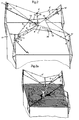
- FIG. 1a shows a sunroof tarpaulin with two tarpaulin parts 1, 2, which are different in shape and size, but lie its two points S, on which pulling ropes 6 and 6 'act, on one and the same perpendicular to the axis of a shaft 3 dash-dotted line.
- Fig.1b can by Tips S of tarpaulin parts 1, 2 going tensile directions (ropes 6, 6 ') also run parallel next to each other, with the tarpaulin parts 1, 2 can have different shape and size and on the Shaft axis are shifted against each other.
- a perfect one symmetrical arrangement of the tarpaulin parts 1, 2 is in Fig.1c shown.
- the tarpaulin parts 1, 2 can be conventional in themselves and therefore not further illustrated the shaft 3 along its fold line or along its edges (if there are separate tarpaulin parts).
- the shaft 3 consists of a grooved tube, the Groove serves the tarpaulin parts by means of an attached Fasten the welt by pushing it into the groove.
- Fig.2 the two are diagonally opposite one another Corners of a folded and rolled up on a shaft 3 Plane shown that consists of two different sized parts 1, 2 consists.
- the shaft 3 can be rotated via a drive 4, and on it are wound reels 5, 5 ', the preferred ones Design explained in more detail below with reference to FIG. 5 shall be.
- a protective tape 24 is applied to the longer tarpaulin part 1, on which winds the rope 6 'of the shorter tarpaulin part 2.
- the Cable 6 runs, starting from one winding roll 5, over a pulley 7 attached to a post 14 and one Tensioning roller 8 to an upper deflection roller 9 on an upright 11 '.
- the latter can consist of two independently rotatable rollers consist.
- the cable 6 runs from the deflection roller 9 a similar deflection roller 10 on the post 11 'and on a pull roller 12 on the tarpaulin part 1 and then back to the Deflection rollers 10, 9, the two going to the tension roller 12 Cable components move in the same direction.
- At one by the drive 4 e.g.
- the entire tarpaulin roof sits by means of the uprights 14, 14 'and 11, 11 ', which carry the tarpaulin or sunroof, on the walls of a cubic building 17.
- the Fig.2a leaves this in a more descriptive way Recognize wise.
- the flat roof of the building is in this Presentation dashed horizontally for better emphasis. On him the shadow of a person is drawn below the rolled up tarpaulin roof.
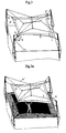
- FIG 3 shows the tarpaulin roof device shown in FIG with tensioned tarpaulin 1, 2, and also the drive shaft 3 is shown slightly bent upwards. This bend is desired and the consequence of the deflection rollers 7, 7 ' exerted inclined pull. If you extend the uprights (11, 11 ', 14, 14 'in Fig.2) upwards, so you can move the point of attack the direction of the diagonal pull of the roller suspension and thus change its effect. The stronger the diagonal pull, i.e. the higher the suspension of the deflection rollers 7, 7 ', the more of course the bend of the shaft 3 is stronger the possibility of moving the winding rollers 5, 5 'on the shaft 3.
- Figure 3 is also the use of UV protective strips 1 ", 2" shown on the edges of the tarpaulin parts, 1, 2, which protect the more sensitive tarpaulin when rolled up.
- FIG. 3a again shows the arrangement shown in FIG. however, for better illustration with one under the Shadow of tarpaulin standing people.
- the angular shadow of the Tarpaulin appears on the hatched flat roof.
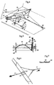
- FIG. Another exemplary embodiment is shown in FIG. in which the drivable shaft 3, on which the tarpaulin is rolled, is carried by a bracket spanning them or the like 18, which in turn by means of supports 19, 20 on a house wall or on Rafters can be attached.
- a bracket spanning them or the like 18, which in turn by means of supports 19, 20 on a house wall or on Rafters can be attached.
- a single winding roll 27 is used; two tension rollers 25, 25 'are resiliently suspended.
- the shaft 3 can also be cantilevered above it Building parts can be arranged. So the tarpaulin can e.g. one span a small courtyard and a flat roof. The possible use this embodiment is therefore very universal.
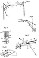
- FIG. 5 shows a preferred embodiment of the winding roll, whose roller body 31 is not completely cylindrical, but is slightly conical.
- the winding roll or drum is according to Fig.5 with their Axis of rotation e.g. on a wall 39 or on a stand attached.
- the material for the ropes 34, 35 is e.g. Steel wire and a polyamide for the drum. Every rope is made from a number (e.g. 19) of twisted wires. The rope strength depends on the desired resilience.
- the winding roll can in a conventional manner Electric motor to be housed to drive it.
- the Figure 7 represents schematically a cross section through the abrasion protection band 24 including one rope lying on it.
- Fig.8 which the generation of a shaft 3 bend Turn shows, again 4 designate a drive and 7 or 7 'each a pulley.
- the latter are here by means of a short Rope to a higher point of post 14 or 14 ' tense.
- the cable pulls 6, 6 ' are analogous to one another. from the respective winding roll 5 or 5 ', over which at an angle Deflection pulley 7 or 7 'braced above the upright 14 or 14' guided.
- the shaft 3 is bent slightly upwards.
- By moving the winding roll 5 or 5 'on the shaft 3 can the bending moment on shaft 3 can be changed.
- This effect can be done by moving the point of attachment of the suspension influence the deflection rollers 7, 7 'even further.
- FIG. 9 shows the suspension of a deflection roller 42 on a articulated and braced against a fixed point a tube formed support 40, at the upper end of one Bracket 41 is seated, which is inserted into the support tube.
- a Similar bracket is shown in Fig.10.
- Carrier tube inserted holder part 41 has a number of Bores 42 through which the tensioning cables can be guided, which are provided with crimped clamps 43 on the inside, so to prevent the respective rope from slipping.
- FIG. 11 shows an at least currently particularly preferred Tarpaulin roof arrangement, in which a cantilever 43 two guide rollers 44, 45 carries, by means of which the entire cable 6, 6 ' with pulley 46, 47 and above the sunroof the only spring 48 are kept high enough.
- the Angle between the cantilever 43 on the shaft 3 is approximately 30 °.
- Both the two pulleys 44, 45 and the Attachment of the single spring 48 are adjustable. It can two springs are also provided starting from point 49, one of which on the pulley 46 and the other on the Deflection roller 47 acts to the tension of the sun roof receive.
- On the edges of the tarpaulin are known per se Way protective strips attached to the tarpaulin itself in the Completely cover the rolled up condition.
- the shaft 3 with the Winding roll 5 can at one end, below the Krägägers 43, cardamic, whereas they are on the other Preferred end - in view of the bends in operation - is kept longitudinally displace
- a tab is shown in the diagonal, which for Connection of the tarpaulin with the associated pull rope 6 or 6 'serves.
- This is in a double loop 62, the a solid fabric is made, a slotted bolt 63.
- the loop 62 is attached to the top of the tarpaulin.
- the Traction rope 6 or 6 ' is when inserting the bolt 63 in it Slot 64 inserted after it was previously crimped with Terminals 66, 66 'was provided, these terminals 66, 66' one Hold rope loop 67 together.
- the operation of the system i.e. stretching or curling the sunroof or tarpaulin in general, can also be program controlled take place, so that e.g. at certain times and / or the tarpaulin automatically in certain weather conditions is rolled out or rolled up. This can be done in known Sensors are used in a circuit known per se.
Landscapes
- Engineering & Computer Science (AREA)
- Architecture (AREA)
- Civil Engineering (AREA)
- Structural Engineering (AREA)
- Physics & Mathematics (AREA)
- Electromagnetism (AREA)
- Tents Or Canopies (AREA)
- Mechanical Treatment Of Semiconductor (AREA)
- Massaging Devices (AREA)
- Steroid Compounds (AREA)
- Building Awnings And Sunshades (AREA)
- Inorganic Insulating Materials (AREA)
- Soil Working Implements (AREA)
- Compression-Type Refrigeration Machines With Reversible Cycles (AREA)
- Addition Polymer Or Copolymer, Post-Treatments, Or Chemical Modifications (AREA)
- Glass Compositions (AREA)
Description
Claims (36)
- Verstellbares Planendach mit einer Plane (1, 2), die im Bereich einer Teil- oder Faltlinie an einer einzelnen, an Trägern (14, 14'; 18) drehbar gelagerten und mit einem einzigen Antrieb versehenen Welle (3) befestigt und auf dieser aufrollbar ist, dadurch gekennzeichnet, daß zum Auf- bzw. Abrollen der durch die Teil- oder Faltlinie gegebenen Planenteile (1, 2) wenigstens zwei Seilzüge (6, 6') vorgesehen sind, die an den Planenteilen (1, 2) angreifen und auf die Welle (3) aufrollbar sind.
- Planendach nach Anspruch 1, dadurch gekennzeichnet, daß die Seilzüge (6, 6'), die je an einem Planenteil (1, 2) angreifen, auf wenigstens eine auf der Welle sitzende Wickelrolle (5, 5') aufrollbar sind.
- Planendach nach Anspruch 1 oder 2, dadurch gekennzeichnet, daß die Punkte (S) der Planenteile (1, 2), an denen der jeweilige Seilzug (6, 6') befestigt ist, auf ein und derselben zur Welle (3) senkrechten Linie liegen.
- Planendach nach Anspruch 1 oder 2, dadurch gekennzeichnet, daß die Punkte (S) der Planenteile (1, 2), an denen der jeweilige Seilzug (6, 6') befestigt ist, auf zwei verschiedenen, zueinander parallelen und zur Welle (3) senkrechten Linien liegen.
- Planendach nach Anspruch 1 oder 2, dadurch gekennzeichnet, daß die Planenteile (1, 2) im ausgerollten Zustand an der Faltlinie gegeneinander versetzt sind.
- Planendach nach einem der Ansprüch 1 bis 3, dadurch gekennzeichnet, daß die Planenteile (1, 2) zueinander symmetrisch sind.
- Planendach nach einem der Ansprüche 3 bis 5, dadurch gekennzeichnet, daß die Planenteile (1, 2) verschieden groß und/oder verschieden geformt sind.
- Planendach nach Anspruch 3, dadurch gekennzeichnet, daß die Planenteile (1, 2) gleich groß, jedoch an der Faltlinie gegeneinander versetzt sind.
- Planendach nach einem der Ansprüche 1 bis 8, dadurch gekennzeichnet, daß die Planenteile (1, 2) dreieckig sind.
- Planendach nach einem der Ansprüche 1 bis 9, dadurch gekennzeichnet, daß zum Ausgleich der verschiedenen Abrollängen und zur Spannung der Seilzüge (6, 6') zumindest ein elastisches Glied (15, 16; 48) vorgesehen ist.
- Planendach nach Anspruch 10, dadurch gekennzeichnet, daß das elastische Glied (15, 16; 48) als Schraubenfeder ausgebildet ist.
- Planendach nach Anspruch 10 oder 11, dadurch gekennzeichnet, daß das elastische Glied (15, 16; 48) so angeordnet ist, daß es die Seilzüge (6, 6') zueinander zieht, wobei im Falle eines einzigen elastischen Gliedes (48) an diesem zwei Umlenkrollen (46, 47) oder eine Zweifachrolle befestigt sind bzw. ist, über welche je ein Seilzug (6, 6') geführt ist.
- Planendach nach Anspruch 12, dadurch gekennzeichnet, daß der Befestigungspunkt (49) des elastischen Gliedes (48) in der Höhe über der Welle (3) verstellbar ist und die Zuführung der beiden Seilzüge (6, 6') zu einer einzigen Wickelrolle (5) über Führungsrollen (44, 45) erfolgt, die an einem Kragträger (43) befestigt sind, so daß die zur Wickelrolle (5) führenden Seilzüge (6, 6') ausreichend hoch über dem Dach gehalten sind.
- Planendach nach Anspruch 10 oder 11, dadurch gekennzeichnet, daß zwei elastische Glieder (15, 16) so angeordnet sind, daß sie die zwei Seilzüge (6, 6') zueinander ziehen, wobei jedes elastische Glied an jedem Ende über eine daran befestigte Spannrolle (8, 8' bzw. 13, 13') mit einem der Seilzüge (6, 6') verbunden ist.
- Planendach nach einem der Ansprüche 2 bis 11 und 14, dadurch gekennzeichnet, daß auf der Antriebswelle (3) seitlich der aufgerollten Plane (1, 2) je eine Wickelrolle (5, 5') befestigt ist, wobei von jeder der beiden Wickelrollen (5, 5') zwei an ihr befestigte Seile ausgehen, deren jedes dem einen oder anderen Seilzug (6, 6') zugehört und über Umlenkrollen (7, 7'), die an Festpunkten, z.B. Stehern (14, 14'), aufgehängt sind, zu Spannrollen (13, 13'), die die beiden Seilzüge (6, 6') federnd zueinander ziehen, über an weiteren Festpunkten aufgehängten Umlenkrollen (9, 9' und 10, 10') zu je einer an jedem Planenteil (1, 2) befestigten Zugrolle (12, 12') geführt ist und von dort über Umlenkrollen und Spannrollen zur anderen Wickelrolle (5') verläuft.
- Planendach nach Anspruch 15, dadurch gekennzeichnet, daß der Verlauf der beiden Seilzüge (6, 6') gleichartig und symmetrisch ist.
- Planendach nach einem der Ansprüche 1 bis 16, dadurch gekennzeichnet, daß die Welle (3) an jedem ihrer beiden Enden fest, z.B. an einem Steher (14, 14'), gelagert ist, wobei die eine Lagerung als motorischer Antrieb oder Handantrieb ausgebildet ist.
- Planendach nach einem der Ansprüche 1 bis 16, dadurch gekennzeichnet, daß die Welle (3) an einem sie überspannenden Bügel (18) gelagert ist, welcher seinerseits durch fest angebrachte Träger (19, 20) gehalten ist.
- Planendach nach Anspruch 18, dadurch gekennzeichnet, daß auf der Welle (3) nur eine einzige Wickelrolle (27) sitzt, wobei jeder von dieser Wickelrolle (27) ausgehende Seilzug (6, 6') über eine Umlenkrolle (28) zu Spannrollen (25, 25') und weiter zu an Fixpunkten sitzenden Umlenkrollen (26, 26') und von dort zu den Zugecken der Planenteile verläuft.
- Planendach nach einem der Ansprüche 1 bis 19, dadurch gekennzeichnet, daß die aufrollbaren Planenteile (1, 2) in einem von 180° abweichenden Winkel zueinander ziehbar sind, z.B. zu einer Art Zeltdach ausziehbar sind.
- Planendach nach einem der Ansprüche 2 bis 18 oder 20, dadurch gekennzeichnet, daß jeder der beiden Seilzüge (6, 6') ausgehend von den Wickelrollen (5, 5') zuerst über eine, vorzugsweise über der Wellenlagerung fest aufgehängte Rolle (7, 7') geführt ist, wobei der Zug im Seil so bemessen ist, daß eine gewünschte Biegung der Welle (3), vorzugsweise nach oben, erzielt wird.
- Planendach nach einem der Ansprüche 1 bis 21, dadurch gekennzeichnet, daß die Umlenk- und allenfalls die Spannrollen feststehende, seitlich der eigentlichen Rolle angebrachte, im Durchmesser wesentlich größere Seitenplatten aufweisen, die ein Herausspringen des Seiles verhindern.
- Planendach nach einem der Ansprüche 1 bis 17 und 20 bis 22, dadurch gekennzeichnet, daß vier die Plane und die Seilzüge tragende Steher (11, 11', 14, 14') vorgesehen sind, wobei zwei diagonal gegenüberliegende Steher (14, 14') die Antriebswelle (3) tragen und die beiden anderen (11, 11') Seilrollen zur Umlenkung.
- Planendach nach Anspruch 23, dadurch gekennzeichnet, daß die Steher als abgespannte Masten ausgebildet sind.
- Planendach nach einem der Ansprüche 1 bis 24, dadurch gekennzeichnet, daß die Wickelrollen (5, 5') örtlich verstellbar sind.
- Planendach nach einem der Ansprüche 2 bis 25, dadurch gekennzeichnet, daß an jedem der beiden Seilzüge (6, 6') bzw. ihren Befestigungsstellen mindestens eine Sollbruchstelle als Schutz gegen Überlastung, z.B. durch Winddruck, vorgesehen ist.
- Planendach nach einem der Ansprüche 1 bis 26, dadurch gekennzeichnet, daß die Welle (3) an zumindest einem Ende verschiebbar und/oder kardanisch gelagert ist.
- Planendach nach einem der Ansprüche 1 bis 27, dadurch gekennzeichnet, daß im Falle von ungleich langen Planenteilen auf dem längeren Planenteil (1) ein Scheuerschutzband (24), gegebenenfalls mit Seitenwülsten (24'), angebracht ist, auf welches sich das Zugseil des kürzeren Planenteils aufwickelt.
- Planendach nach einem der Ansprüche 1 bis 28, dadurch gekennzeichnet, daß jeder Teil der Plane mit Randschutzstreifen (1", 2") versehen ist, die so bemessen sind, daß sie die Plane im aufgerollten Zustand abdecken.
- Planendach nach einem der Ansprüche 2 bis 29, dadurch gekennzeichnet, daß die bzw. jede Wickelrolle (5, 5') bezüglich ihrer Drehachse leicht konisch ist, wobei der Konuswinkel gegenüber der Achse vorzugsweise unter 1° liegt, und daß die Wickelrolle an ihrem dickeren Ende gerundet in eine im Durchmesser größere Endplatte (32) übergeht und die Zuführung des bzw. der aufzuwickelnden Seile (6, 6') knapp entlang der Endplatte (32) im Bereich des größten Durchmessers der Rundung (33) erfolgt, wobei das aufzuwickelnde Seil bzw. die Seile (34, 35) im Bereich (37) des dünneren Endes der Wickelrolle (30), vorzugsweise an einer dort befindlichen Endplatte (38), befestigbar bzw. befestigt sind.
- Planendach nach einem der Ansprüche 1 bis 30, dadurch gekennzeichnet, daß die Seile über Mehrfachrollen oder Rollen mit mehreren Rillen geführt sind.
- Planendach nach einem der Ansprüche 2 bis 31, dadurch gekennzeichnet, daß die bzw. eine Wickelrolle innen einen Elektromotor aufweist, der ihren Außenmantel antreibt.
- Planendach nach einem der Ansprüche 30 bis 32, dadurch gekennzeichnet, daß die Gleitfähigkeit des oder der aufzuwickelnden Seile mit der Gleitfähigkeit des Rollenmantels und dem Radius der Rundung (33) des Überganges von der Manteloberfläche zur Endplatte (32) so abgestimmt ist, daß die Seilwindungen am annähernd größten Rundungsdurchmesser eine ausreichend große in Richtung der Rollenachse gerichtete Druckkraft auf die bereits vorher aufgewickelten Seilwindungen erzeugen, wodurch diese Seilwindungen kontinuierlich auf den Rollenmantel gegen das schlankere Ende zu geschoben werden.
- Planendach nach einem der Ansprüche 1 bis 33, dadurch gekennzeichnet, daß Abspannseile an Stehern (40) oder dergl., die rohrförmig ausgebildet sind, mittels in das Rohrende eingesteckter Pfropfen (41) befestigt sind, welche Pfropfen das Rohrende übergreifen und eine Anzahl Bohrungen (42), die z.B. kreisförmig angeordnet sind, aufweisen, wobei die Abspannseile durch diese Bohrungen geführt und unterhalb derselben mit aufgepreßten Muffen (43) versehen sind, die ein Herausrutschen verhindern.
- Planendach nach einem der Ansprüche 1 bis 34, dadurch gekennzeichnet, daß zur Befestigung der Seile (65) an den Planenteilen an diesen befestigte Zweifachlaschen (62) dienen, durch welche ein geschlitzter Bolzen (63) geschoben ist, durch dessen Schlitz das Seil (6, 6') gesteckt ist, das dahinter mit aufgepreßten Muffen (66, 66') versehen ist, die eine Seilschlaufe (67) zusammenhalten.
- Planendach nach einem der Ansprüche 1 bis 35, dadurch gekennzeichnet, daß die Welle (3), auf der die Plane bzw. die Planenteile (1, 2) aufrollbar sind, aus einem mit einer Nut versehenen Rohr, vorzugsweise einem Stahlrohr, besteht, wobei die Plane mittels eines in die Nut eingeschobenen Keders am Rohr befestigt ist.
Applications Claiming Priority (7)
| Application Number | Priority Date | Filing Date | Title |
|---|---|---|---|
| AT198495 | 1995-12-06 | ||
| AT1984/95 | 1995-12-06 | ||
| AT198595 | 1995-12-06 | ||
| AT198595 | 1995-12-06 | ||
| AT198495 | 1995-12-06 | ||
| AT1985/95 | 1995-12-06 | ||
| PCT/AT1996/000242 WO1997021014A1 (de) | 1995-12-06 | 1996-12-06 | Verstellbares planendach |
Publications (2)
| Publication Number | Publication Date |
|---|---|
| EP0865557A1 EP0865557A1 (de) | 1998-09-23 |
| EP0865557B1 true EP0865557B1 (de) | 2000-08-23 |
Family
ID=25597348
Family Applications (1)
| Application Number | Title | Priority Date | Filing Date |
|---|---|---|---|
| EP96940626A Expired - Lifetime EP0865557B1 (de) | 1995-12-06 | 1996-12-06 | Verstellbares planendach |
Country Status (12)
| Country | Link |
|---|---|
| US (1) | US6012505A (de) |
| EP (1) | EP0865557B1 (de) |
| AT (1) | ATE195788T1 (de) |
| AU (1) | AU711146B2 (de) |
| CA (1) | CA2239719C (de) |
| DE (1) | DE59605799D1 (de) |
| ES (1) | ES2150697T3 (de) |
| GR (1) | GR3034836T3 (de) |
| IL (1) | IL124726A (de) |
| NZ (1) | NZ323647A (de) |
| PT (1) | PT865557E (de) |
| WO (1) | WO1997021014A1 (de) |
Cited By (10)
| Publication number | Priority date | Publication date | Assignee | Title |
|---|---|---|---|---|
| DE10333407A1 (de) * | 2003-07-15 | 2005-02-10 | Herzog Gmbh & Co Kg | Planendach |
| DE102006047899B3 (de) * | 2006-10-10 | 2008-04-30 | Warema Renkhoff Gmbh | Sonnen- und Regenschutzanlage |
| DE102007019741A1 (de) * | 2007-04-26 | 2008-10-30 | Bayerische Motoren Werke Aktiengesellschaft | Rollo für den Innenhimmel eines Kraftfahrzeuges |
| DE202010004125U1 (de) | 2010-01-12 | 2010-06-24 | Trs Sonnenschutz Und Steuerungstechnik Gmbh | Schutzvorrichtung, insbesondere aufrollbares Sonnensegel |
| DE202009018220U1 (de) | 2008-03-11 | 2011-08-01 | Plaspack Netze Gmbh | Spannvorrichtung für ein von einer Wickelwelle abziehbares Sonnensegel |
| DE102011112523A1 (de) | 2010-09-08 | 2012-04-26 | Rudolf Steiner | Sonnensegel |
| DE202013104660U1 (de) | 2013-10-15 | 2013-11-12 | Kurt Stimpfl | Sonnensegel |
| DE102013104777A1 (de) | 2013-05-08 | 2014-11-13 | Peter Kochenrath | Aufrollbares Sonnensegel mit an einem Spannseil angreifenden Spannvorrichtung |
| DE102020006894B3 (de) | 2020-11-04 | 2022-03-31 | Arne Albrecht | Aufwickelbare Beschattungs-, Sicht- oder Wetterschutzplane |
| EP4033047A1 (de) | 2021-01-22 | 2022-07-27 | Warema Renkhoff SEd | Sonnenschutzanlage mit einem zugsystem |
Families Citing this family (31)
| Publication number | Priority date | Publication date | Assignee | Title |
|---|---|---|---|---|
| US6003269A (en) * | 1997-04-07 | 1999-12-21 | Mcree; Richard T. | Retractable covering for spaces |
| US6140576A (en) * | 1998-04-06 | 2000-10-31 | Motorola, Inc. | Protective shield tent and method of using same |
| DE10256929A1 (de) * | 2002-12-05 | 2004-06-24 | Arvinmeritor Gmbh | Rollosystem, insbesondere für ein Sonnendach |
| US7185667B2 (en) * | 2004-09-20 | 2007-03-06 | Rottmann Andrew A | Tent frame and canopy |
| US7766024B2 (en) * | 2004-09-20 | 2010-08-03 | Rottmann Andrew A | Tent frame and canopy |
| US7575010B2 (en) * | 2004-09-20 | 2009-08-18 | Rottmann Andrew A | Tent frame and canopy |
| US7472739B2 (en) * | 2004-10-29 | 2009-01-06 | Pt Tech, Inc | Shade structures |
| GB2421520A (en) * | 2004-12-21 | 2006-06-28 | Daniel Cutler | Moveable cover or awning |
| DE202005001875U1 (de) * | 2005-02-05 | 2005-05-19 | Rewalux Markisenvertrieb Gmbh | Verstellbares Sonnensegel mit einer Plane |
| DE102005013490A1 (de) * | 2005-03-22 | 2006-10-05 | Vajsman, Peter | Verstellbares Sonnenschutzsegel |
| CN101326334B (zh) * | 2005-10-11 | 2010-06-02 | 伊藤收 | 可移动遮篷装置及外角遮布的卷绕辊 |
| JP4674381B2 (ja) * | 2005-12-13 | 2011-04-20 | 収 伊藤 | 複合オーニング装置及び複数キャンバスの巻取りローラ |
| EP1974107B1 (de) * | 2006-01-17 | 2014-08-06 | Rezidencija Martina Doo | Verfahren zum abwickeln/wickeln eines laminaren flächengebildes und zur implementierung des verfahrens geeignete wickelstruktur zur abdeckung von flächen |
| GB0606579D0 (en) * | 2006-03-31 | 2006-05-10 | Cutler Daniel | Covering system |
| US20070256796A1 (en) * | 2006-05-05 | 2007-11-08 | Wedin Donald S | Modified awning roll bar |
| GB2450111A (en) * | 2007-06-12 | 2008-12-17 | Daniel Cutler | A retractable covering System |
| US7472873B1 (en) | 2007-06-20 | 2009-01-06 | Long Noah D | Unsupported span and method of use |
| AT507791B1 (de) * | 2009-02-10 | 2010-08-15 | Plaspack Netze Gmbh | Beschattungsvorrichtung |
| WO2011101876A1 (en) * | 2010-02-18 | 2011-08-25 | Velombra Srl | Unwinding and/or winding device, particularly for awnings and the like |
| DE102011113678A1 (de) * | 2011-05-12 | 2012-11-15 | Marc Wronka | Gewichtsgesteuertes Winddruckentlastungssystem |
| DE102012210824B4 (de) * | 2012-06-26 | 2014-03-20 | SL Rasch GmbH Special & Lightweight Structures | Wandelbares Dachelement, Dachkonstruktion und Verfahren zum Betrieb des Dachelements |
| ITVI20120152A1 (it) * | 2012-06-27 | 2013-12-28 | Andrea Bettega | Struttura di copertura perfezionata, in particolare del tipo a vela. |
| JP6339414B2 (ja) * | 2014-05-27 | 2018-06-06 | タカノ株式会社 | 巻き取り式タープ |
| WO2016181303A1 (en) * | 2015-05-13 | 2016-11-17 | Sailshadow S.R.L. | Shade sail |
| US9528313B1 (en) * | 2015-09-30 | 2016-12-27 | Nathan Dhilan Arimilli | Non-intrusive, adaptive tracking and shading device |
| IT201600092215A1 (it) * | 2016-09-13 | 2018-03-13 | Bega S R L | Assieme di copertura ed ombrellone a vela comprendente detto assieme |
| EP3372746A1 (de) * | 2017-03-07 | 2018-09-12 | Plaspack Netze GmbH | Beschattungsvorrichtung |
| EP3572597A1 (de) | 2018-05-10 | 2019-11-27 | Bega S.r.l. | Überdachungsanordnung für sonnenschutz und vorzugsweise eine segeltuchmarkise |
| EP3918156A4 (de) * | 2019-04-10 | 2022-10-26 | JKL Corporation | Zelte |
| IT201900019175A1 (it) * | 2019-10-17 | 2021-04-17 | Bega S R L | Sistema di protezione di un'area mediante un telo parasole relativo kit e metodo |
| US20260062950A1 (en) * | 2024-09-03 | 2026-03-05 | Disney Enterprises, Inc. | Deployable canopy system |
Family Cites Families (13)
| Publication number | Priority date | Publication date | Assignee | Title |
|---|---|---|---|---|
| US721993A (en) * | 1902-03-20 | 1903-03-03 | Effie Arnett | Tent, canopy, or awning. |
| US2350758A (en) * | 1942-06-12 | 1944-06-06 | Hans H A Heuer | Winding device for retractable roofs |
| US3510996A (en) * | 1966-03-17 | 1970-05-12 | Nicholas B Popil | Retractable covering |
| US3952758A (en) * | 1971-09-03 | 1976-04-27 | Addison Frank F | Canopy |
| US4487212A (en) * | 1978-05-06 | 1984-12-11 | Moore Richard P | Vehicle ports or vehicle covering systems and apparatus |
| FR2431827A1 (fr) * | 1978-07-25 | 1980-02-22 | Rantz Louis Michel | Dispositif pour decouvrir des batiments tels que des serres a couverture notamment en film plastique |
| DE3029465A1 (de) * | 1980-08-02 | 1982-03-25 | Bäckmann, Reinhard, Ing.(grad.), 8751 Heimbuchenthal | Textile ueberdachung fuer spielplaetze u.ae. freiflaechen |
| US4724882A (en) * | 1986-10-27 | 1988-02-16 | Wang Jeng Horng | Adjustable awning structure |
| FR2668195B1 (fr) * | 1990-10-17 | 1998-11-20 | Jet Plastique Sarl | Dispositif de climatisation d'abri de piscine, par relevage de film par un tambour enrouleur mobile mu electriquement. |
| US5287908A (en) * | 1991-12-19 | 1994-02-22 | Hunter Douglas Inc. | Window covering assembly |
| US5524693A (en) * | 1993-05-24 | 1996-06-11 | Hamilton; Roy S. | Flexible partition |
| US5437298A (en) * | 1993-11-24 | 1995-08-01 | Lin; Chen Y. | Sunshade arrangement |
| AUPM287193A0 (en) * | 1993-12-09 | 1994-01-06 | Gale Australia Proprietary Limited | Canopy structures |
-
1996
- 1996-12-06 US US09/077,765 patent/US6012505A/en not_active Expired - Lifetime
- 1996-12-06 NZ NZ323647A patent/NZ323647A/xx unknown
- 1996-12-06 CA CA002239719A patent/CA2239719C/en not_active Expired - Fee Related
- 1996-12-06 DE DE59605799T patent/DE59605799D1/de not_active Expired - Lifetime
- 1996-12-06 AT AT96940626T patent/ATE195788T1/de active
- 1996-12-06 WO PCT/AT1996/000242 patent/WO1997021014A1/de not_active Ceased
- 1996-12-06 AU AU10640/97A patent/AU711146B2/en not_active Ceased
- 1996-12-06 PT PT96940626T patent/PT865557E/pt unknown
- 1996-12-06 IL IL12472696A patent/IL124726A/xx not_active IP Right Cessation
- 1996-12-06 EP EP96940626A patent/EP0865557B1/de not_active Expired - Lifetime
- 1996-12-06 ES ES96940626T patent/ES2150697T3/es not_active Expired - Lifetime
-
2000
- 2000-11-13 GR GR20000402524T patent/GR3034836T3/el unknown
Cited By (12)
| Publication number | Priority date | Publication date | Assignee | Title |
|---|---|---|---|---|
| DE10333407A1 (de) * | 2003-07-15 | 2005-02-10 | Herzog Gmbh & Co Kg | Planendach |
| DE102006047899B3 (de) * | 2006-10-10 | 2008-04-30 | Warema Renkhoff Gmbh | Sonnen- und Regenschutzanlage |
| DE102006047899C5 (de) * | 2006-10-10 | 2009-11-12 | Warema Renkhoff Gmbh | Sonnen- und Regenschutzanlage |
| DE102007019741A1 (de) * | 2007-04-26 | 2008-10-30 | Bayerische Motoren Werke Aktiengesellschaft | Rollo für den Innenhimmel eines Kraftfahrzeuges |
| DE202009018220U1 (de) | 2008-03-11 | 2011-08-01 | Plaspack Netze Gmbh | Spannvorrichtung für ein von einer Wickelwelle abziehbares Sonnensegel |
| DE202010004125U1 (de) | 2010-01-12 | 2010-06-24 | Trs Sonnenschutz Und Steuerungstechnik Gmbh | Schutzvorrichtung, insbesondere aufrollbares Sonnensegel |
| DE102011112523A1 (de) | 2010-09-08 | 2012-04-26 | Rudolf Steiner | Sonnensegel |
| DE102013104777A1 (de) | 2013-05-08 | 2014-11-13 | Peter Kochenrath | Aufrollbares Sonnensegel mit an einem Spannseil angreifenden Spannvorrichtung |
| DE202013104660U1 (de) | 2013-10-15 | 2013-11-12 | Kurt Stimpfl | Sonnensegel |
| DE102020006894B3 (de) | 2020-11-04 | 2022-03-31 | Arne Albrecht | Aufwickelbare Beschattungs-, Sicht- oder Wetterschutzplane |
| EP4033047A1 (de) | 2021-01-22 | 2022-07-27 | Warema Renkhoff SEd | Sonnenschutzanlage mit einem zugsystem |
| DE102021101419A1 (de) | 2021-01-22 | 2022-07-28 | Warema Renkhoff Se | Sonnenschutzanlage mit einem Zugsystem |
Also Published As
| Publication number | Publication date |
|---|---|
| GR3034836T3 (en) | 2001-02-28 |
| IL124726A (en) | 2000-12-06 |
| EP0865557A1 (de) | 1998-09-23 |
| AU1064097A (en) | 1997-06-27 |
| ES2150697T3 (es) | 2000-12-01 |
| CA2239719A1 (en) | 1997-06-12 |
| ATE195788T1 (de) | 2000-09-15 |
| DE59605799D1 (de) | 2000-09-28 |
| PT865557E (pt) | 2001-02-28 |
| IL124726A0 (en) | 1999-01-26 |
| CA2239719C (en) | 2005-05-24 |
| NZ323647A (en) | 1999-03-29 |
| WO1997021014A1 (de) | 1997-06-12 |
| AU711146B2 (en) | 1999-10-07 |
| US6012505A (en) | 2000-01-11 |
Similar Documents
| Publication | Publication Date | Title |
|---|---|---|
| EP0865557B1 (de) | Verstellbares planendach | |
| DE19520162A1 (de) | Markise | |
| EP0982466B1 (de) | Wickeljalousie | |
| AT506083B1 (de) | Spannvorrichtung für ein von einer wickelwelle abziehbares sonnensegel | |
| DE3818929A1 (de) | Aufrollbares sonnenschutzdach fuer wintergaerten oder dgl. | |
| DE102013008252B4 (de) | Sonnensegel mit Aufwicklung | |
| DE102016111664A1 (de) | Roll-Markise | |
| DE4139312A1 (de) | Abdeckvorrichtung | |
| DE3841139A1 (de) | Sonnenschutzanlage fuer flaechige glasabdeckungen, insbesondere wintergartendaecher | |
| DE8703605U1 (de) | Rollo für Automobilfenster, insbesondere für PKW-Heckscheiben | |
| DE202010004125U1 (de) | Schutzvorrichtung, insbesondere aufrollbares Sonnensegel | |
| AT503120B1 (de) | Spannvorrichtung für ein von einer wickelwelle abziehbares sonnensegel | |
| DE202015002127U1 (de) | Sonnensegelvorrichtung | |
| DE69103157T2 (de) | Vorhangvorrichtung. | |
| EP3260622B1 (de) | Beschattung mit spannsystem | |
| DE4306498C2 (de) | Abrollbare Abdeckung | |
| AT520680B1 (de) | Spannvorrichtung | |
| DE102017101018B4 (de) | Sonnenschutzrollo mit teilweise geschlossener klappe bei ausgefahrenem behang | |
| DE20218962U1 (de) | Aufrollbare Bedachung nach Art einer Markise oder eines Sonnensegels, zerlegbare Bedachung und Bedachungssystem | |
| DE2358755A1 (de) | Vorrichtung zum abdecken von schwimmbecken | |
| DE19814577C1 (de) | Sonnenschutzanlage | |
| DE29624389U1 (de) | Markise | |
| AT11539U1 (de) | Sonnensegel oder zelt | |
| DE202007009717U1 (de) | Anordnung mit einer Beschattungseinrichtung für ein lichtdurchlässiges Flächenelement | |
| DE10012922C1 (de) | Vorrichtung zum Entfalten mindestens eines Masts mit veränderlichem Querschnitt aus einer aufgerollten Transportstellung |
Legal Events
| Date | Code | Title | Description |
|---|---|---|---|
| PUAI | Public reference made under article 153(3) epc to a published international application that has entered the european phase |
Free format text: ORIGINAL CODE: 0009012 |
|
| 17P | Request for examination filed |
Effective date: 19980612 |
|
| AK | Designated contracting states |
Kind code of ref document: A1 Designated state(s): AT CH DE ES FR GR IT LI MC PT |
|
| GRAG | Despatch of communication of intention to grant |
Free format text: ORIGINAL CODE: EPIDOS AGRA |
|
| GRAG | Despatch of communication of intention to grant |
Free format text: ORIGINAL CODE: EPIDOS AGRA |
|
| GRAH | Despatch of communication of intention to grant a patent |
Free format text: ORIGINAL CODE: EPIDOS IGRA |
|
| 17Q | First examination report despatched |
Effective date: 20000324 |
|
| GRAH | Despatch of communication of intention to grant a patent |
Free format text: ORIGINAL CODE: EPIDOS IGRA |
|
| GRAA | (expected) grant |
Free format text: ORIGINAL CODE: 0009210 |
|
| AK | Designated contracting states |
Kind code of ref document: B1 Designated state(s): AT CH DE ES FR GR IT LI MC PT |
|
| REF | Corresponds to: |
Ref document number: 195788 Country of ref document: AT Date of ref document: 20000915 Kind code of ref document: T |
|
| REG | Reference to a national code |
Ref country code: CH Ref legal event code: EP |
|
| REF | Corresponds to: |
Ref document number: 59605799 Country of ref document: DE Date of ref document: 20000928 |
|
| ITF | It: translation for a ep patent filed | ||
| REG | Reference to a national code |
Ref country code: CH Ref legal event code: NV Representative=s name: ISLER & PEDRAZZINI AG |
|
| REG | Reference to a national code |
Ref country code: ES Ref legal event code: FG2A Ref document number: 2150697 Country of ref document: ES Kind code of ref document: T3 |
|
| ET | Fr: translation filed | ||
| REG | Reference to a national code |
Ref country code: PT Ref legal event code: SC4A Free format text: AVAILABILITY OF NATIONAL TRANSLATION Effective date: 20001123 |
|
| PLBE | No opposition filed within time limit |
Free format text: ORIGINAL CODE: 0009261 |
|
| STAA | Information on the status of an ep patent application or granted ep patent |
Free format text: STATUS: NO OPPOSITION FILED WITHIN TIME LIMIT |
|
| 26N | No opposition filed | ||
| REG | Reference to a national code |
Ref country code: CH Ref legal event code: PCAR Free format text: ISLER & PEDRAZZINI AG;POSTFACH 1772;8027 ZUERICH (CH) |
|
| REG | Reference to a national code |
Ref country code: FR Ref legal event code: PLFP Year of fee payment: 20 |
|
| PGFP | Annual fee paid to national office [announced via postgrant information from national office to epo] |
Ref country code: GR Payment date: 20151112 Year of fee payment: 20 Ref country code: CH Payment date: 20151211 Year of fee payment: 20 |
|
| PGFP | Annual fee paid to national office [announced via postgrant information from national office to epo] |
Ref country code: ES Payment date: 20151119 Year of fee payment: 20 Ref country code: PT Payment date: 20151111 Year of fee payment: 20 Ref country code: AT Payment date: 20151223 Year of fee payment: 20 Ref country code: MC Payment date: 20151223 Year of fee payment: 20 |
|
| PGFP | Annual fee paid to national office [announced via postgrant information from national office to epo] |
Ref country code: DE Payment date: 20151229 Year of fee payment: 20 Ref country code: IT Payment date: 20151210 Year of fee payment: 20 |
|
| PGFP | Annual fee paid to national office [announced via postgrant information from national office to epo] |
Ref country code: FR Payment date: 20151231 Year of fee payment: 20 |
|
| REG | Reference to a national code |
Ref country code: DE Ref legal event code: R071 Ref document number: 59605799 Country of ref document: DE |
|
| REG | Reference to a national code |
Ref country code: CH Ref legal event code: PL |
|
| REG | Reference to a national code |
Ref country code: AT Ref legal event code: MK07 Ref document number: 195788 Country of ref document: AT Kind code of ref document: T Effective date: 20161206 |
|
| REG | Reference to a national code |
Ref country code: GR Ref legal event code: MA Ref document number: 20000402524 Country of ref document: GR Effective date: 20161207 |
|
| PG25 | Lapsed in a contracting state [announced via postgrant information from national office to epo] |
Ref country code: PT Free format text: LAPSE BECAUSE OF EXPIRATION OF PROTECTION Effective date: 20161215 |
|
| PG25 | Lapsed in a contracting state [announced via postgrant information from national office to epo] |
Ref country code: ES Free format text: LAPSE BECAUSE OF EXPIRATION OF PROTECTION Effective date: 20161207 |