EP0866195A2 - Vorrichtung zur Verankerung einer Fassadenverkleidung über einer Dämmung an einer Wand - Google Patents
Vorrichtung zur Verankerung einer Fassadenverkleidung über einer Dämmung an einer Wand Download PDFInfo
- Publication number
- EP0866195A2 EP0866195A2 EP98100771A EP98100771A EP0866195A2 EP 0866195 A2 EP0866195 A2 EP 0866195A2 EP 98100771 A EP98100771 A EP 98100771A EP 98100771 A EP98100771 A EP 98100771A EP 0866195 A2 EP0866195 A2 EP 0866195A2
- Authority
- EP
- European Patent Office
- Prior art keywords
- wall
- elongated hole
- circular disk
- anchoring
- area
- Prior art date
- Legal status (The legal status is an assumption and is not a legal conclusion. Google has not performed a legal analysis and makes no representation as to the accuracy of the status listed.)
- Withdrawn
Links
- 238000004873 anchoring Methods 0.000 title claims abstract description 15
- 238000009413 insulation Methods 0.000 title claims abstract description 12
- 238000005253 cladding Methods 0.000 claims abstract description 12
- 230000007704 transition Effects 0.000 claims abstract description 4
- 239000003638 chemical reducing agent Substances 0.000 description 16
- 239000011505 plaster Substances 0.000 description 3
- 239000004793 Polystyrene Substances 0.000 description 1
- 239000002657 fibrous material Substances 0.000 description 1
- 239000012774 insulation material Substances 0.000 description 1
- 229920002223 polystyrene Polymers 0.000 description 1
- 230000003014 reinforcing effect Effects 0.000 description 1
- 230000003068 static effect Effects 0.000 description 1
Images


Classifications
-
- E—FIXED CONSTRUCTIONS
- E04—BUILDING
- E04F—FINISHING WORK ON BUILDINGS, e.g. STAIRS, FLOORS
- E04F13/00—Coverings or linings, e.g. for walls or ceilings
- E04F13/07—Coverings or linings, e.g. for walls or ceilings composed of covering or lining elements; Sub-structures therefor; Fastening means therefor
- E04F13/08—Coverings or linings, e.g. for walls or ceilings composed of covering or lining elements; Sub-structures therefor; Fastening means therefor composed of a plurality of similar covering or lining elements
- E04F13/0801—Separate fastening elements
- E04F13/0803—Separate fastening elements with load-supporting elongated furring elements between wall and covering elements
- E04F13/0805—Separate fastening elements with load-supporting elongated furring elements between wall and covering elements with additional fastening elements between furring elements and the wall
-
- E—FIXED CONSTRUCTIONS
- E04—BUILDING
- E04B—GENERAL BUILDING CONSTRUCTIONS; WALLS, e.g. PARTITIONS; ROOFS; FLOORS; CEILINGS; INSULATION OR OTHER PROTECTION OF BUILDINGS
- E04B1/00—Constructions in general; Structures which are not restricted either to walls, e.g. partitions, or floors or ceilings or roofs
- E04B1/62—Insulation or other protection; Elements or use of specified material therefor
- E04B1/74—Heat, sound or noise insulation, absorption, or reflection; Other building methods affording favourable thermal or acoustical conditions, e.g. accumulating of heat within walls
- E04B1/76—Heat, sound or noise insulation, absorption, or reflection; Other building methods affording favourable thermal or acoustical conditions, e.g. accumulating of heat within walls specifically with respect to heat only
- E04B1/762—Exterior insulation of exterior walls
- E04B1/7637—Anchoring of separate elements through the lining to the wall
Definitions
- the invention relates to a device for anchoring a facade cladding by means of a Substructure above an insulation on a wall with a wall bracket with at least an elongated hole in the wall bracket for anchoring to the wall with the help of Anchoring bolt.
- the object of the invention is now to improve on the prior art To provide fastening device for substructures, in which it is possible to use one and the same Wall bracket with different screws of different diameters on a wall fasten.
- a device of the type mentioned in which one in essential circular disk-shaped reducing disk with continuous, round inner bore is provided, the reducer an upper circular disc area with an upper Has outer diameter that is larger than the transverse diameter of the elongated hole, and a lower circular disc area with a lower outer diameter that is less than that Transverse diameter of the elongated hole, and being the transition from the upper to the lower Circular disk area runs essentially step-like.
- the reducer is placed on the elongated hole placed that the lower circular disc area protrudes into the opening of the elongated hole.
- the Outer diameter of the lower circular disc area should be only slightly less than that Cross diameter of the elongated hole, so that the reducer in the longitudinal direction of the Slotted hole is slidable, but has little play in the transverse direction.
- the upper circular disc area the reducer always protrudes at least on the long sides of the elongated hole beyond the edge of the hole so that the reducer does not pass through it Hole can pass through.
- the inner bore of the reducer should have a diameter have, which is little larger than the diameter of the anchor bolt to be used not allow the bolt too much freedom of movement in the bore.
- the thickness or height of the lower circular disc area measured perpendicular to the disc surface, less than the thickness of the wall bracket in the area of the elongated hole. That's the only way possible, the wall bracket when screwing the reducer between it and the wall to engage in a clamp.
- the reducer would be the lower circular disc area protruding into the elongated hole the reducer is higher or as high as the thickness of the U-web, so the reducer would touch the wall after screwing it in, and the console could be in the slot area under the outer sections of the top Circular disk area are moved along, which is undesirable.
- that would Small contact area of the lower circular disc area of the reducer when tightening the screw cause damage to the wall, which is the case with the large contact surface Wall bracket is not the case.
- the wall bracket is advantageously designed as a square U, L or Z profile, but also other shapes are suitable.
- the elongated holes are preferably attached in the U-web, which is provided for anchoring the console on the wall is.
- the facade cladding is then attached via the after anchoring in U-leg of the bracket projecting essentially perpendicularly from the wall.
- the elongated holes can also be provided in one of the U-legs with U-shaped brackets be, in which case the fastening of the facade cladding to the second, opposite U-leg is done.
- Wall brackets with L or Z profiles are anchored to the Wall and the fastening of the facade cladding accordingly.
- Figure 1 shows the fastening device according to the invention in horizontal section, one U-shaped wall bracket 1 and a reducer 2 are shown, with a screw 3rd and a dowel 4 are screwed to a wall 7.
- a hole is provided in the wall 7.
- the screw 3 extends are through the inner bore of a reducer 2, the upper Circular disc area above the elongated hole 6 to beyond the edges of the Extends inside of the U-web of the wall bracket 1.
- the lower circular area of the Reducer 2 protrudes into the elongated hole 6, but does not touch the wall 7.
- an insulation 8 attached, through which the U-leg of the wall bracket 1 in extend substantially perpendicularly from the wall 7.
- the U-legs protrude from the insulation 8, where they via screws 13 are screwed to the U-legs of a second U-profile 5.
- screws 10 is a plaster base plate 9 as part of a facade cladding on the U-web of the second U-profile 5 fixed.
- a reinforcing layer 11 is arranged above the plaster base plate 9 and a layer above it Surface plaster 12 applied.
- the elongated hole 6 extends in the longitudinal direction of the U-webs of the wall bracket 1.
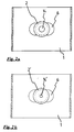
- Figures 2a and 2b is a view of the inside of the same U-bridge shown, but with different reducers 2 and 2 '.
- the Reducing discs 2 and 2 ' differ only in the diameter of their inner bores 14 or 14 'for corresponding fastening screws.
- the height of the lower circular disk area of the reducing disk 2 is lower and about half the thickness of the U-victory of the wall bracket 1.
- the transition from the top Circular disk area to the lower circular disk area of the reduction disk 2 from FIGS. 3a or 3b is stepped and is the edge boundaries of the elongated hole 6 in adapted essentially form-fitting.
Landscapes
- Engineering & Computer Science (AREA)
- Architecture (AREA)
- Civil Engineering (AREA)
- Structural Engineering (AREA)
- Finishing Walls (AREA)
- Load-Bearing And Curtain Walls (AREA)
Abstract
Description
Claims (2)
- Vorrichtung zur Verankerung einer Fassadenverkleidung (9) mittels einer Unterkonstruktion über einer Dämmung (8) an einer Wand (7) mit einer Wandkonsole (1) mit wenigstens einer Langlochbohrung (6) In der Wandkonsole (1) für die Verankerung an der Wand (7) mit Hilfe von Verankerungsbolzen (3), dadurch gekennzeichnet, daß eine im wesentlichen kreisscheibenförmige Reduzierscheibe (2) mit durchgehender, runder Innenbohrung (14, 14') vorgesehen ist, wobei die Reduzierscheibe (2) einen oberen Kreisscheibenbereich mit einem oberen Außendurchmesser, der größer ist als der Querdurchmesser der Langlochbohrung (6), und einen unteren Kreisscheibenbereich mit einem unteren Außendurchmesser, der geringer ist als der Querdurchmesser der Langlochbohrung (6), aufweist und wobei der Übergang vom oberen zum unteren Kreisscheibenbereich im wesentlichen stufenförmig verläuft.
- Vorrichtung nach Anspruch 1, dadurch gekennzeichnet, daß die Höhe des unteren Kreisscheibenbereiches senkrecht zur Scheibenfläche geringer ist als die Dicke der Wandkonsole (1) im Bereich der Langlochbohrung (6).
Applications Claiming Priority (2)
| Application Number | Priority Date | Filing Date | Title |
|---|---|---|---|
| DE19712200A DE19712200A1 (de) | 1997-03-22 | 1997-03-22 | Vorrichtung zur Verankerung einer Fassadenverkleidung über einer Dämmung an einer Wand |
| DE19712200 | 1997-03-22 |
Publications (2)
| Publication Number | Publication Date |
|---|---|
| EP0866195A2 true EP0866195A2 (de) | 1998-09-23 |
| EP0866195A3 EP0866195A3 (de) | 2000-08-02 |
Family
ID=7824381
Family Applications (1)
| Application Number | Title | Priority Date | Filing Date |
|---|---|---|---|
| EP98100771A Withdrawn EP0866195A3 (de) | 1997-03-22 | 1998-01-17 | Vorrichtung zur Verankerung einer Fassadenverkleidung über einer Dämmung an einer Wand |
Country Status (2)
| Country | Link |
|---|---|
| EP (1) | EP0866195A3 (de) |
| DE (1) | DE19712200A1 (de) |
Cited By (3)
| Publication number | Priority date | Publication date | Assignee | Title |
|---|---|---|---|---|
| WO2004099527A1 (en) * | 2003-05-08 | 2004-11-18 | Grp Refurbishment Systems Limited | Mobile fixing |
| FR2873139A1 (fr) * | 2004-07-13 | 2006-01-20 | Thierry Pierre Etienn Marechal | Systeme de montage et de fixation pour isolant mince entre une ossature metallique et un parement |
| EP2700766A1 (de) * | 2012-08-23 | 2014-02-26 | BWM Dübel + Montagetechnik GmbH | Fassadenbefestigungsvorrichtung |
Families Citing this family (1)
| Publication number | Priority date | Publication date | Assignee | Title |
|---|---|---|---|---|
| DE19947913C2 (de) * | 1999-10-06 | 2002-08-29 | Karl-Heinz Fingerling | Befestigungselement zur Anbringung von Lasten an eine eine Wärmedämmung aufweisende Gebäudewand |
Family Cites Families (10)
| Publication number | Priority date | Publication date | Assignee | Title |
|---|---|---|---|---|
| US3006443A (en) * | 1954-12-20 | 1961-10-31 | Joseph T Siler | Method and apparatus for attaching juxtaposed members |
| DE2656481C2 (de) * | 1976-12-14 | 1983-01-05 | Franz 2000 Norderstedt Dwuzet | Unterlegscheibe |
| DE8118469U1 (de) * | 1981-06-25 | 1981-10-22 | Rheinhold & Mahla Gmbh, 6800 Mannheim | Schneidplatte |
| DE8432958U1 (de) * | 1984-11-10 | 1985-04-25 | Dynamit Nobel Ag, 5210 Troisdorf | Befestigungsscheibe zum Fixieren von lose aufgelegten Dichtungsbahnen |
| FR2585782B1 (fr) * | 1985-08-02 | 1990-07-20 | Koenig Jean Rene | Equerre reglable amelioree pour le maintien de deux parois |
| GB2202247B (en) * | 1987-03-13 | 1991-03-20 | Gartner & Co J | Device for securing facade elements. |
| DE3723755A1 (de) * | 1987-03-13 | 1988-11-03 | Gartner & Co J | Vorrichtung zur befestigung von fassadenelementen |
| DE8707863U1 (de) * | 1987-06-03 | 1987-07-30 | DIG Deutsche Innenbau GmbH, 4330 Mülheim | Bauelementesatz zum Anschließen eines Bauelementes an ein U-förmiges Profil |
| DE8900021U1 (de) * | 1989-01-03 | 1989-03-09 | Sikla GmbH & Co KG, 7201 Hausen | Vorgeformte Montageschiene |
| GB9022430D0 (en) * | 1990-10-16 | 1990-11-28 | Clark George Sheffield Ltd | Cam washer adjusting device |
-
1997
- 1997-03-22 DE DE19712200A patent/DE19712200A1/de not_active Withdrawn
-
1998
- 1998-01-17 EP EP98100771A patent/EP0866195A3/de not_active Withdrawn
Cited By (3)
| Publication number | Priority date | Publication date | Assignee | Title |
|---|---|---|---|---|
| WO2004099527A1 (en) * | 2003-05-08 | 2004-11-18 | Grp Refurbishment Systems Limited | Mobile fixing |
| FR2873139A1 (fr) * | 2004-07-13 | 2006-01-20 | Thierry Pierre Etienn Marechal | Systeme de montage et de fixation pour isolant mince entre une ossature metallique et un parement |
| EP2700766A1 (de) * | 2012-08-23 | 2014-02-26 | BWM Dübel + Montagetechnik GmbH | Fassadenbefestigungsvorrichtung |
Also Published As
| Publication number | Publication date |
|---|---|
| EP0866195A3 (de) | 2000-08-02 |
| DE19712200A1 (de) | 1998-09-24 |
Similar Documents
| Publication | Publication Date | Title |
|---|---|---|
| EP0921252B1 (de) | Befestigungselement zur Abstandsbefestigung von Latten, Profilen, Platten oder dergleichen | |
| EP2454423B1 (de) | Wandstruktur für ein gebäude | |
| DE69001655T2 (de) | Beschlag fuer einstellbare befestigung von aussenbekleidungspaneelen. | |
| DE4226742A1 (de) | Verkleidungselement für Böden, Decken, Wände und Fassaden | |
| EP2715156B1 (de) | System zum befestigen einer dämmfassade und dafür vorgesehener befestiger | |
| AT509145B1 (de) | Abstandshalter und verfahren für die befestigung eines gegenstandes an einem eine dämmschicht aufweisenden untergrund | |
| EP0464367A1 (de) | Bauelementesatz zur Erstellung eines Tragwerks für Reinraumdecken | |
| EP0069698A2 (de) | Wärmedämmende Platte | |
| EP0866195A2 (de) | Vorrichtung zur Verankerung einer Fassadenverkleidung über einer Dämmung an einer Wand | |
| EP0972891A2 (de) | Vorrichtung für die Befestigung von Glasscheiben an Gebäudefassaden | |
| CH697354B1 (de) | Hinterlüftete wärmegedämmte Gebäudefassade. | |
| AT409510B (de) | Wand- und fassaden-system | |
| EP1319790B1 (de) | Fenster- und Türanker | |
| DE69000524T2 (de) | Trag- und verankerungsvorrichtung fuer platten von rahmenloser verglasung oder fassadenwand. | |
| DE102005040388A1 (de) | Stützverbund für Gebäude sowie Teile zu seiner Herstellung | |
| DE69102954T2 (de) | Heizelement für eine Fussbodenheizung. | |
| DE29612763U1 (de) | Holzhaus und zu dessen Herstellung bestimmte Wandtafel | |
| DE10321345B4 (de) | Befestigungssystem für hohlstabförmige Keramikprofile | |
| DE3907293C2 (de) | Stütze für in Räumen, Etagen oder ähnlichem angeordnete Trennwände oder dergleichen | |
| DE4101133C2 (de) | Verfahren zur Befestigung von Bahnen an Holzwolle-Leichtbauplatten | |
| DE3644726A1 (de) | Fassadendaemmelement mit hinterlueftung | |
| DE102022119007A1 (de) | Befestigungssystem für ein Fassadenelement und Verfahren zur Befestigung | |
| DE102010015281B4 (de) | Verfahren zum Verlegen eines Fußbodensystems | |
| EP0872604A1 (de) | Verankerungsvorrichtung zum Einbetten in Beton und Verfahren zu deren Herstellung | |
| DE2431175A1 (de) | Ankerschiene |
Legal Events
| Date | Code | Title | Description |
|---|---|---|---|
| PUAI | Public reference made under article 153(3) epc to a published international application that has entered the european phase |
Free format text: ORIGINAL CODE: 0009012 |
|
| AK | Designated contracting states |
Kind code of ref document: A2 Designated state(s): AT BE CH DE DK ES FI FR GB GR IE IT LI LU MC NL PT SE |
|
| AX | Request for extension of the european patent |
Free format text: AL;LT;LV;MK;RO;SI |
|
| PUAL | Search report despatched |
Free format text: ORIGINAL CODE: 0009013 |
|
| AK | Designated contracting states |
Kind code of ref document: A3 Designated state(s): AT BE CH DE DK ES FI FR GB GR IE IT LI LU MC NL PT SE |
|
| AX | Request for extension of the european patent |
Free format text: AL;LT;LV;MK;RO;SI |
|
| AKX | Designation fees paid | ||
| REG | Reference to a national code |
Ref country code: DE Ref legal event code: 8566 |
|
| STAA | Information on the status of an ep patent application or granted ep patent |
Free format text: STATUS: THE APPLICATION IS DEEMED TO BE WITHDRAWN |
|
| 18D | Application deemed to be withdrawn |
Effective date: 20010205 |