The present invention relates to communication
systems, and more particularly to radio frequency
communications between the two or more distant users via a
radio frequency transponder or payload that is attached to
a satellite orbiting the Earth.
In conventional three axis communications spacecraft
the radio frequency transponders (or "the payload") on the
spacecraft consist of a receiving reflector antenna (usually
a shaped reflector) that forms the radiation pattern for
reception of electromagnetic signals. The received signals
are amplified with a low noise amplifier and then are
frequency converted to the transmit frequency. The frequency
converted signals are passed through a demultiplexer that
separates the various received signals into their respective
frequency bands. The separated signals are amplified by
travelling wave tube amplifiers (TWTAs), one for each
frequency band and are combined in a multiplexer to form the
high power transmit signal - the high power signal is passed
through a transmit reflector antenna (usually a shaped
reflector) that forms the transmit radiation pattern.
The large heat dissipating equipment (i.e. the TWTAs
and multiplexer) in the transponder are usually located in
the spacecraft bus on the north and south thermal radiating
panels of the spacecraft. The transmit and receive reflector
antenna are usually deployed outboard from the east and west
sides of the spacecraft bus.
There are three basic problems with conventional
satellite transponders of the type described. The first
problem is that as the spacecraft power capability is
increased the dissipated heat generated by the spacecraft
also increases. The only way dissipated heat can be rejected
from a spacecraft of the type described is by radiation from
the north and south thermal radiating panels. Since the
amount of heat that can be radiated is proportional to the
area of the thermal radiating panels, the spacecraft must
get larger as the spacecraft power is increased. This causes
problems with fitting the satellite in the launch vehicle
faring.
A second problem is that the shaped reflector
antennas (or the array fed reflector antennas) that are
commonly used on spacecraft of the type described have
radiation patterns that can not be readily changed in orbit.
Antenna coverage requirements are usually selected one to
two years before the satellite launch. Since many operators
of commercial communications satellites do not know exactly
what the market requirements will be in three to five years,
they must guess what the antenna pattern requirements will
be and hope they don't change much over the ten to fifteen
year spacecraft life. This is very risky financially. Having
antenna radiation patterns that can be reconfigured in orbit
would be very attractive to satellite operators.
A third problem is that conventional spacecraft
transponders of the type described have custom designed
antenna systems that change with each application.
Eliminating such custom designed components will allow
standardization of design and stock piling of parts which in
turn can reduce delivery time. Reducing delivery time is
also very attractive to satellite operators.
Solutions to the three problems previously described
are known to us. These solutions involve the use of a
deployed active array antenna. Active array antennas are
distinguished by having a Solid State Power Amplifier (SSPA)
at every individually phase weighted antenna element in the
array. This is opposed to passive array antennas which have
no means of RF power amplification in the array.
Examples of deployed active array antenna
solutions include U.S. patents 5,327,150 and 5,293,171 and
the related U.S. patent 4,987,425. These patents adapt
deployed array antenna technology originally developed for
space radar and apply it to geostationary communications
satellites. The deployed active array antenna technology as
described in the aforesaid patents may also use deployed
passive array antenna technology that has been used in
several operational spacecraft including the US. SEASAT
satellite and Canada's RADARSAT satellites.
More particularly, U.S. Patent 5,327,150 issued July
5, 1994 to Cherrette entitled "PHASED ARRAY ANTENNA FOR
EFFICIENT RADIATION OF MICROWAVE AND THERMAL ENERGY"
discloses an active phased array antenna that includes a
plurality of subarrays having an upper RF radiating panel
assembly including a plurality of radiating waveguides and
a feed waveguide. RF radiating slots are cut into one wall
of each of the radiating waveguide and a mirror with
corresponding slot is bonded to the outside surface. The
array further includes a non-RF radiating lower support
panel assembly with a mirror bonded to the outside face. The
mirrors efficiently radiate thermal energy in the presence
of sunlight. An active electronics module is mounted in a
housing, and includes an RF probe. The module is supplied
with RF signals, control signals and DC bias voltage over
transmission lines contained in a multilayered circuit
board. RF energy emitted by the probe is coupled from the
feed waveguide to the radiating waveguides. Heat generated
by the electronics module is conducted through the housing
of the active electronics modules and transferred to the
outer surfaces of the upper and lower panel assemblies where
it is radiated into cold space.
U.S. Patent 5,293,171 issued Mar. 8, 1994 to
Cherrette entitled: PHASED ARRAY ANTENNA FOR EFFICIENT
RADIATION OF HEAT AND ARBITRARILY POLARIZED MICROWAVE SIGNAL
POWER discloses an active phased array antenna panel that
radiates heat and arbitrarily polarized microwave signal
power. The active array panel also reflects solar power to
minimize solar heating. The active array panel includes a
plurality of subarray elements each of which includes a
plurality of aperture coupled patch radiators. The exterior
surface of the subarray element is covered with mirrors to
provide efficient radiation of heat in the presence of
sunlight. A microstrip feed network in the subarray element
is embedded in a dielectric material with a high thermal
conductivity to efficiently distribute heat. The active
array further includes an electronics module for each
subarray element. The electronics module contains a solid
state power amplifier, phase shifter and associated
electronics mounted in a housing made of material with high
thermal conductivity. Each electronics module and
corresponding subarray element are thermally and
electrically connected to each other and to a support
structure assembly with mirrors bonded to the lower exterior
surface. Heat generated by the circuits in the electronics
module is conducted through the housing and transferred to
the outer surfaces of the subarray element and support
structure assemblies where it is radiated into space.
U.S. Patent 4,987,423 issued Jan. 22, 1991 to Zahn
et al. entitled ANTENNA SUPPORT STRUCTURE discloses a
carrying structure of an active antenna that uses fiber
reinforced synthetic material in which heat conductive
elements and/or elements conducting electromagnetic waves
are integrated into the support structure for the antenna.
The biggest problem with the deployed active array
antenna solution is that SSPA saturated efficiency is very
low and in many cases the SSPAs must be operated linear by
which further reduces efficiency. A typical deployed active
array payload for geostationary satellite communications may
require more than twice as much DC power as a conventional
payload for the same application. Another problem is that to
produce and package the large number of SSPAs as required
for this type of payload, a major development effort would
be needed.
The present invention seeks to provide a transponder
(payload) for communications spacecraft that overcomes or at
least substantially reduces some of the aforesaid problems
associated with conventional payloads.
According to the invention there is provided an
electrically reconfigurable passive array antenna panel for
radiating thermal energy and transmitting RF signals
comprising at least one passive transmit array antenna,
disposed in said antenna panel, said at least one said
passive transmit array antenna having a multiplexer means
and a plurality of travelling wave tube amplifiers, the
travelling wave tube amplifiers providing amplified RF
signals to the multiplexer means, the multiplexer means
being connected to the at least one passive transmit array
antenna, wherein the at least one passive transmit subarray
antenna transmits the RF signals and radiates dissipated
heat from the electronically reconfigurable passive array
antenna panel. The invention also includes a spacecraft
provided with a deployable antenna panel as previously
defined.
The present invention also seeks to provide a
payload on a spacecraft that does not require deployed
active array technology.
The present invention may enable the integration of
conventional TWTAs and multiplexers onto passive transmit
array antenna panels and deploying these panels out board of
a spacecraft bus.
The invention permits the provision of a spacecraft
transponder that permits one or more of the following
improvements, antenna pattern flexibility in orbit, high DC
to RF power conversion efficiency, facilitates higher
spacecraft power and helps reduce satellite delivery time.
The present invention permits the provision of a
spacecraft with deployed payload panel architecture with
multiple independent beams that can be electronically
reconfigured on the ground or in orbit.
The present invention permits the provision of a
spacecraft on which the deployed payload is constructed from
modular deployed panels that radiate all internally
generated heat and are thermally isolated from the
spacecraft bus such that payload power does not depend on
bus size and can be increased by deploying more payload
panels.
In order that the invention and its various other
preferred features may be understood more easily, some
embodiments thereof will now be described, by way of example
only, with reference to the drawings in which:_
Figs. 1, 2 and 3 are illustrations showing how the
deployed payload of the present invention is attached to a
spacecraft.
Fig. 4 is an illustration of a section of a deployed
passive phased array panel.
Figs. 5 and 6 are illustrations of a back surface
and an end view of passive phased array antenna panel.
Fig. 7 is an illustration depicting how a deployed
passive phased array antenna panel radiates all internally
generated heat and RF power out from the front and back
surfaces.
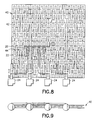
Figs. 8 and 9 are back and side views of a more
detailed illustration of a quarter section of a deployed
passive phased array panel containing one phased array
antenna.
Like numerals refer to like parts throughout the
disclosure.
Figures 1, 2 and 3 are illustrations that
conceptually show how a deployed payload is attached to a
spacecraft 10. In Figure 1, the payload panels 12 and 14 are
shown stored. Figure 2 shows the panels 12 and 14 partially
deployed from spacecraft 10 and Figure 3 shows panels 12 and
14 fully deployed from spacecraft 10. Payload panels 12 and
14 are deployed from the east and west sides of the
spacecraft in a manner similar to the deployment of the
solar arrays. In the stowed configuration of Figure 1,
multiple payload panels can be stacked along the east and
west sides of the spacecraft bus.
Payload panels 12 and 14 are composed of one or more
passive array transmit antennas that use ferrite phase
shifters to electronically control the antenna radiation
pattern shape. The array antenna structure is used to
support TWTAs and multiplexers and performs both thermal and
RF radiating functions. Standardized panels with standard
mechanical interfaces can be designed for C band, Ku band or
Ka band. By selecting the number and type of panels used,
many payload configurations are possible including hybrid
C/Ku band payloads.
An active array receive antenna 15 can be employed
to produce multiple reconfigurable antenna patterns for the
up link. The active receive array 15 can be mounted on the
nadir facing panel of the spacecraft as shown in Figures 1,
2 or 3 or they can be on deployed panels 12 and 14.
Figure 4 through Figure 9 show the construction
detail for a Ku band transmit panel. It will be apparent to
those versed in the art that the same design principles can
be extended to lower frequencies like C band or higher
frequencies such as Ka band.
Figure 4 shows an illustration of a section of a Ku
band transmit panel that uses waveguide fed slot radiators
16 for the RF radiating surface. The RF radiating surface is
coated with a thermal control material that has high thermal
emissivity and low solar absorption so that it can
efficiently radiate dissipated heat in the presence of
sunlight. This material may be optical solar reflecting
mirrors, or various type of thermal control paints. The back
surface of the panel (not visible in Figure 4) may be coated
with a similar thermal control material as the front RF
radiating surface.
Figure 5 shows a view of the back surface of a Ku
band transmit panel. The back surface includes four transmit
arrays 18 each comprising a four channel multiplexer 20 and
four waveguides 22. There are a total of sixteen waveguides
on the panel surface that connect the four multiplexers to
sixteen TWTAs 24.
Figure 6 is an illustration of the end view of the
panel of Figure 5. In this particular embodiment the panel
is 8 ft. by 8 ft. and is composed of the four 4 ft. Ku band
transmit arrays 18. Each 4 ft. by 4 ft. transmit array is
fed by four radiatively cooled TWTAs 24 that have their
individual output signal power combined in a four channel
multiplexer 20.
Figure 5 also illustrates a section of the back
thermal radiating surface of one 4 ft. by 4 ft. transmit
array 38 partially removed so that the construction details
of the passive array antenna are visible.
Figure 7 depicts the flow of radiated heat from both
the front and back surfaces of the Ku band transmit panel of
Figs. 5 and 6. Figure 7 also depicts the flow of RF
radiation from the front side of the panel.
Figure 8 and Figure 9 show a more detailed
illustration of the back and end views of the 4ft. by 4 ft.
transmit array antenna with the back thermal radiating
surface fully removed. The 4 ft. by 4 ft. Ku band transmit
array shown in Figure 8 is composed of two hundred and fifty
six array antenna elements 40 that use two hundred and fifty
six ferrite phase shifters 42 to electronically control the
antenna radiating pattern shape. In this particular
embodiment the antenna element is a slotted waveguide
subarray consisting of sixteen slots arranged in four rows
of four slots. The assembly of slotted waveguide subarray
elements can be manufactured together in one large piece
using standard dip braze manufacturing techniques.
The slotted waveguide subarray elements 40 in
Figures 8 and 9 are fed by a ferrite phase shifter modules
42. The phase shifter modules 42 are in turn fed by the
waveguide corporate feed network 44 in Figure 8. The
assembly of these three types of components forms the
passive transmit array antenna.
The passive array antenna is the mechanical support
structure for the TWTAs and multiplexers and performs both
thermal and RF radiating functions. The passive array is fed
by the multiplexer 20 which is in turn fed by the various
TWTAs 24. Depending on the thermal dissipation, heat pipes
may be required to provide a more even temperature
distribution. The back thermal radiating surface is
mechanically attached to the back side of the panel
assembly.
Although the embodiment just described is for a Ku
band transmit panel 8 ft. by 8 ft. in size having sixteen
TWTAs, it should be clear to those versed in the art that
the panel size could be varied and the number of TWTAs can
be varied depending on the design specifics. Such design
specifics include panel operating temperature, dissipation
per TWTA, type of TWTA (radiatively cooled or conductivity
cooled) etc. It should also be clear to those versed in the
art that the same architecture can be used for other
frequencies. For example C band transmit panels and Ka band
transmit panels can be designed with the same architecture.
A significant feature of the construction is the
integration of conventional TWTAs 24 and multiplexers 20
onto passive transmit array antenna panels and deploying
these panels out board of the spacecraft bus. It should be
noted that the multiplexer 20 may in some cases be replaced
by a simple filter or power combiner or both.
The described construction simultaneously provides
antenna pattern flexibility in orbit, high DC to RF power
conversion efficiency, facilitates higher spacecraft power
and helps reduce satellite delivery time. No other payload
design provides all these attributes. More particularly the
invention provides for in orbit antenna pattern
reconfigurability. The deployed payload panel architecture
will provide multiple independent beams that can be
electronically reconfigured on the ground or in orbit.
The construction also facilitates higher spacecraft
power. The deployed payload is constructed from modular
deployed panels that radiate all internally generated heat
and are thermally isolated from the bus. Consequently
payload power does not depend on bus size and can be
increased by deploying more payload panels.
The construction will help reduce satellite delivery
time. The deployed payload is constructed from modular
panels that are composed of standardized parts which can be
stock piled. Consequently, the schedule bottlenecks
associated with custom designed payloads are eliminated.
Large antenna aperture areas that can be stowed into a small
launch envelop also provide flexibility in payload
configuration.
The DC to RF power conversion efficiency for the
deployed payload is greater than or equal to that of a
conventional payload because waveguide runs after the TWTAs
are shorter in the deployed payload. The DC to RF power
conversion efficiency for the deployed payload is much
greater than that of a payload with active array transmit
antenna. This is due to the much higher power conversion
efficiency of TWTAs as compared to SSPAs.