EP0867585A2 - Profilteil zur Verbindung flächiger Teile - Google Patents
Profilteil zur Verbindung flächiger Teile Download PDFInfo
- Publication number
- EP0867585A2 EP0867585A2 EP98104258A EP98104258A EP0867585A2 EP 0867585 A2 EP0867585 A2 EP 0867585A2 EP 98104258 A EP98104258 A EP 98104258A EP 98104258 A EP98104258 A EP 98104258A EP 0867585 A2 EP0867585 A2 EP 0867585A2
- Authority
- EP
- European Patent Office
- Prior art keywords
- profile
- parts
- profile part
- sealing ribs
- recess
- Prior art date
- Legal status (The legal status is an assumption and is not a legal conclusion. Google has not performed a legal analysis and makes no representation as to the accuracy of the status listed.)
- Withdrawn
Links
Images


Classifications
-
- E—FIXED CONSTRUCTIONS
- E05—LOCKS; KEYS; WINDOW OR DOOR FITTINGS; SAFES
- E05D—HINGES OR SUSPENSION DEVICES FOR DOORS, WINDOWS OR WINGS
- E05D3/00—Hinges with pins
- E05D3/06—Hinges with pins with two or more pins
- E05D3/12—Hinges with pins with two or more pins with two parallel pins and one arm
- E05D3/122—Gear hinges
-
- A—HUMAN NECESSITIES
- A47—FURNITURE; DOMESTIC ARTICLES OR APPLIANCES; COFFEE MILLS; SPICE MILLS; SUCTION CLEANERS IN GENERAL
- A47K—SANITARY EQUIPMENT; ACCESSORIES THEREFOR, e.g. TOILET ACCESSORIES
- A47K3/00—Baths; Showers; Appurtenances therefor
- A47K3/28—Showers or bathing douches
- A47K3/30—Screens or collapsible cabinets for showers or baths
- A47K3/36—Articulated screens
-
- E—FIXED CONSTRUCTIONS
- E05—LOCKS; KEYS; WINDOW OR DOOR FITTINGS; SAFES
- E05D—HINGES OR SUSPENSION DEVICES FOR DOORS, WINDOWS OR WINGS
- E05D5/00—Construction of single parts, e.g. the parts for attachment
- E05D5/02—Parts for attachment, e.g. flaps
- E05D5/0246—Parts for attachment, e.g. flaps for attachment to glass panels
- E05D2005/0261—Parts for attachment, e.g. flaps for attachment to glass panels connecting two or more glass panels
- E05D2005/0269—Parts for attachment, e.g. flaps for attachment to glass panels connecting two or more glass panels the panels being coplanar
-
- E—FIXED CONSTRUCTIONS
- E05—LOCKS; KEYS; WINDOW OR DOOR FITTINGS; SAFES
- E05D—HINGES OR SUSPENSION DEVICES FOR DOORS, WINDOWS OR WINGS
- E05D5/00—Construction of single parts, e.g. the parts for attachment
- E05D5/02—Parts for attachment, e.g. flaps
- E05D5/0246—Parts for attachment, e.g. flaps for attachment to glass panels
-
- E—FIXED CONSTRUCTIONS
- E05—LOCKS; KEYS; WINDOW OR DOOR FITTINGS; SAFES
- E05Y—INDEXING SCHEME ASSOCIATED WITH SUBCLASSES E05D AND E05F, RELATING TO CONSTRUCTION ELEMENTS, ELECTRIC CONTROL, POWER SUPPLY, POWER SIGNAL OR TRANSMISSION, USER INTERFACES, MOUNTING OR COUPLING, DETAILS, ACCESSORIES, AUXILIARY OPERATIONS NOT OTHERWISE PROVIDED FOR, APPLICATION THEREOF
- E05Y2800/00—Details, accessories and auxiliary operations not otherwise provided for
- E05Y2800/15—Applicability
- E05Y2800/16—Applicable on combinations of fixed and movable wings
- E05Y2800/162—Applicable on combinations of fixed and movable wings the wings being coplanar when the movable wing is in the closed position
-
- E—FIXED CONSTRUCTIONS
- E05—LOCKS; KEYS; WINDOW OR DOOR FITTINGS; SAFES
- E05Y—INDEXING SCHEME ASSOCIATED WITH SUBCLASSES E05D AND E05F, RELATING TO CONSTRUCTION ELEMENTS, ELECTRIC CONTROL, POWER SUPPLY, POWER SIGNAL OR TRANSMISSION, USER INTERFACES, MOUNTING OR COUPLING, DETAILS, ACCESSORIES, AUXILIARY OPERATIONS NOT OTHERWISE PROVIDED FOR, APPLICATION THEREOF
- E05Y2900/00—Application of doors, windows, wings or fittings thereof
- E05Y2900/10—Application of doors, windows, wings or fittings thereof for buildings or parts thereof
- E05Y2900/114—Application of doors, windows, wings or fittings thereof for buildings or parts thereof for showers
Definitions
- the invention relates to a profile part for a profile, in particular a joint, sealing and / or clamping profile, wherein the profile part has a recess on one side for receiving a flat part and wherein Profile can be formed from two profile parts.
- Such profile parts are used to make flat Parts to connect.
- the flat parts are particularly around shower cubicle walls and mirrors in the bathroom area.
- the flat parts can be different Angles to each other. In some applications is also the pivotability of the flat parts to each other required.
- Profiles are known from the prior art which for different angles, for example 90 ° or 135 ° angle, each can be specially made.
- the Formation of the known profiles depends on whether niche doors, shower walls at right angles to each other, non-rectangular cubicles, pentagonal showers, quarter-circle showers or the like are required.
- the showers belonging to the state of the art have in addition opening problems, since the shower doors in 80 Percent of cases when opening at least partially stand outside over the edge of the shower tray and therefore not can be opened if directly after the shower Furniture, radiators or other parts arranged are. So that these doors can be opened comfortably and sufficiently there must be appropriate space right next to the shower be kept free, which is a waste of Space means. On the other hand, these problems with the Planning a bath will be considered, which unfortunately not often enough.
- the invention is therefore based on the object To create profile part of the type described above, the can be used flexibly, and that with the arrangement in one Profile improved mobility of the flat parts to each other.
- the main advantage, which with the invention over the state of the art is achieved in Creation of a versatile profile part for Connection of flat parts.
- the sealing ribs are two profile parts in one profile can be arranged at any angle to each other. It does not require any special adjustment of the profile parts for the required angular position of the flat parts. This saves machine and time in the manufacture of the profile parts, since no adjustment of the Manufacturing machines to different profile shapes necessary is.
- the at least two sealing ribs in cross section at least formed approximately triangular, whereby the Sealing ribs have good stability with respect to vertical pressure loads occurring to the longitudinal axis of the profile part exhibit.
- This cross-sectional training also supports this the sealing ribs the statics of the entire profile part.
- the triangular trained cross section of the at least two sealing ribs has at least two legs of equal length. This ensures an optimized interlocking of two Profile parts arranged at a fixed distance from each other are.
- An advantageous embodiment of the invention provides before that the converging legs of the Sealing ribs have a rounded end in cross section form, for example, are semicircular, which makes it possible for the sealing ribs to be gear-shaped to arrange. It is also provided according to the invention that the tapered legs of two side by side arranged sealing ribs also in the shape of a circular arc merge.
- the at least two sealing ribs are expedient releasably arranged on the profile part. This allows the number the sealing ribs can be designed variably. In the Manufacturing a profile part is made so that a Maximum number of sealing ribs can be arranged. Corresponding The maximum number can be later for the respective requirement exhausted by the arrangement of the removable sealing ribs be or be undercut.
- An advantageous development of the invention provides before that the at least two sealing ribs by means of dovetail-shaped grooves detachably arranged on the profile part are. This causes the sealing ribs to slide out preventable in case of tensile load.
- the profile part has a circular recess in cross section, the is formed in the part of the profile part on which the at least two sealing ribs are arranged.
- the circular recess on the Entire length of the profile part can be formed, whereby a Material savings can be optimized.
- a metal rod can be arranged. Is the profile part from one slightly flexible material, especially plastic, manufactured, this is how the metal rod ensures the necessary statics of the profile part.
- the profile part in cross section another, kidney-shaped trained recess.
- This serves on the one hand Material savings.
- the wall thicknesses of the entire profile part essentially are the same thickness to avoid that the Warped profile part.
- the profile part two on the side opposite the sealing ribs Has projections, whereby it can be prevented that the in the recess of the profile part arranged flat part collides with another flat part.
- An advantageous embodiment of the invention provides before that the two protrusions symmetrical to the center line of the profile part can be trained. This ensures that the profile part does not tilt when, for example arranged in a U-shaped profile element is, the U-shaped profile element for fixing the Profile part can be used for example on a wall.
- the profile part is expediently made of an aluminum alloy trained, whereby the profile part easily edited can and the weight of the profile part can be minimized.
- the two profile parts are arranged pivotable to each other. This is the angle of the flat parts to each other can be changed.
- the Profile is adaptable to changing conditions. So can, for example, by changing the angle changed spatial dimensions are reacted.
- the two profile parts to each other by 360 ° are pivotable, which optimizes pivotability of the flat parts is given. This is particularly so an advantage if the flat parts are used as door leaves are trained.
- the profile according to the invention is advantageous in this way trained that in any pivot position of the profile parts to each other the chamfers of the interlocking sealing ribs at least partially flat are arranged, whereby in any angular positions a splash-proof connection between the two Profile parts can be trained.
- the two profile parts by means of at least one hinge plate fixable to each other. This is one with little Effortable and easy to assemble connection for given a fixation of the two profile parts to each other.
- hinge pins in the respective circular recess of the two profile parts are arranged, and that the hinge pins through circular openings in the at least one each Grip joint plate. This enables a material-saving, Detachable connection formed between the profile parts will.
- An expedient embodiment of the invention provides before that a first hinge plate at an upper end of the Profile parts and a second hinge plate on a lower one End of the profile parts are arranged. This makes them Articulated plates easily accessible during assembly, which in particular when the joint plates are released later Time saving leads.
- the at least one hinge plate is advantageously slotted arranged in the two profile parts. According to the Invention can be seen on the two flat surfaces of the at least one hinge plate each a hinge sleeve be arranged.
- the hinge plate is thus in the profile integrated and essentially not for a viewer visible.
- the joint sleeves ensure even when slotted arranged hinge plate a splash-proof Connection.
- joint sleeve made of one material, preferably Teflon is executable by means of which limescale are avoidable on the joint sleeve, making a possible long trouble-free function of the profile, especially with using the profile in a shower is.
- one of the two profile parts in one U-shaped wall profile element is arranged, which U-shaped wall profile element can be fixed to a wall.
- the profile part can be easily assembled and with can be detachably arranged on the wall in a short amount of time.
- one of the two profile parts in the U-shaped wall profile element fixable with a screw. This allows simple and quick assembly and release of the profile part in the U-shaped wall profile element.
- FIG. 1 an inventive profile part (1) in Cross section shown.
- the profile part (1) points to the a recess (2) on one side.
- the recess (2) is rectangular in cross section.
- a flat part (3) is arranged in the recess (2) . It can Various flat parts arranged in the recess (2) preferably glass doors and walls, mirrors, Partitions and furniture parts.
- the cross section of the Profile part (1) semicircular, and there are five sealing ribs (4) arranged.
- the sealing ribs (4) are evenly spaced from each other.
- the cross section of the sealing ribs (4) is triangular educated. It is preferably in the form of a isosceles triangle.
- the sealing ribs (4) are rounded.
- the legs of adjacent sealing ribs (4) seen in cross section also run in an arc into each other.
- the number of sealing ribs arranged on the profile part (1) (4) can be varied as required.
- the profile part (1) is with more than five sealing ribs (4) and also with less than five sealing ribs (4) can be implemented.
- each Sealing ribs (4) preferably cut in one single point. Between the elongated center lines (6, 7) adjacent sealing ribs (4) is a non-zero Angle formed.
- the sealing ribs are preferably fixed to the Profile part (1) connected.
- the sealing ribs (4) are detachable on the profile part (1) arranged. For example, with the help of dovetail-shaped grooves in the profile part (1) can be carried out.
- the profile part (1) has a circular recess (8) on.
- the circular recess (8) can entire length of the profile part (1). This has the advantage of substantial material savings.
- the circular recess (8) can be a metal rod be arranged.
- the metal rod advantageously supports the Static of the profile part (1).
- kidney-shaped recess (9) shows the cross section of the profile part (1) a kidney-shaped recess (9).
- This kidney-shaped too Recess (9) can be part of the length or formed over the entire length of the profile part (1) be. On the one hand, this results in further material savings possible. On the other hand, it is achieved that the wall thicknesses of the entire profile part (1) essentially the same are thick to avoid that the profile part (1) in warps. It can also be kidney-shaped trained recess (9) inserted a joint seal will.
- the profile part (1) On one side of the profile part (1), on which the profile part (1) has the recess (2) are two Projections (10, 11) arranged. Between a surface (12) of the recess (2) and a surface (13) of the Projections (10, 11) is formed at a right angle. The other surface (14) of the projections (10) is chamfered. At the end (15) facing away from the recess (2) the projections (10, 11) rounded.
- the projections (10, 11) can also be formed in other shapes. For example, both surfaces (13, 14) the projections (10, 11) beveled.
- the profile part (1) is preferably made of an aluminum alloy manufactured. But it can also be made of plastic or consist of plastic-coated metal.
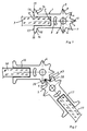
- FIG. 2 shows a profile in cross section.
- Two profile parts (16, 17) according to the invention are arranged such that part of the sealing ribs (4) interlock.
- the profile parts (16, 17) can be moved relative to one another, so that any angular positions between the profile parts (16, 17) can be trained. Depending on the angular position each engage other sealing ribs (4). In However, all angular positions is due to the invention Execution of the sealing ribs (4) ensures that a part of the sealing ribs (4) at least partially flat is arranged together. This is in any Angle positions a splash-proof connection between the profile parts (16, 17) formed.
- this is suitable Profile especially for use in the construction of shower cubicles various kinds. Whether four, five, hexagon or Half-round cabin, all shapes and uses are by means to plan and equip the profile multifunctionally.
- the partition wall should be in the form of an accordion. The angles between adjacent partitions can be changed flexibly.
- the two profile parts (16, 17) are as shown in FIG. 2 arranged to each other that the rounded ends (5) of the interlocking sealing ribs (4) in cross-section rounded space (20) between two neighboring Butt sealing ribs (4).
- the profile parts (16, 17) in one 360 ° position to each other.
- the cross-sectional representation in Fig. 3 shows that the projection (10) of a profile part (16) on the beveled surface (14) of the projection (11) of the other profile part (17) arranged is. This advantageously prevents the flat parts (18, 19) collide and in the process to be damaged.
- 4 A and 4 B show two profile parts (16, 17) in cross section, each with a profile part (17) in one U-shaped wall profile element (21) is arranged.
- 4 A and 4 B is an offset of the two Profile parts (16, 17) to each other to the left or trained right.
- the offset is the Length of one of several flat parts and several profiles existing arrangement variable if the arrangement at least around a corner.
- Profile parts (16, 17) used to build a shower cubicle so can the total length of the shower cabin walls to be connected can be varied by about 10 to 20 mm.
- a profile part (17) can according to FIG. 4 A in a U-shaped Wall profile element (21) are arranged.
- the U-shaped Wall profile element (21) is preferably by means of a Countersunk screw (22) can be fixed to the wall.
- the U-shaped Wall profile element (21) can be carried out so that the projections (10, 11) on the inner surfaces (23, 24) of the U-shaped Apply wall profile element (21). This prevents one Tilting the profile part (17) when fixing by means of a screw (25).
- a flat part (3) arranged, whereby the Recess (2) is preferably completely fillable.
- the profile part (17) is in the U-shaped wall profile element (21) parallel to the center line of the profile part (17) slidable. This can advantageously bumps Wall on which the U-shaped wall profile element (21) is arranged is to be balanced. Furthermore, the total length an arrangement of flat element (3) and Profile parts (16, 17) can be changed, for example, by 10 to 12 mm.
- the profile parts (16, 17) are by means of an articulated plate (27) fixable to each other.
- a front view and a plan view of a preferred embodiment of a hinge plate (27) are shown in Fig. 5.
- the top view is It can be seen that the hinge plate (27) on two opposite Sides is semicircular. She points two circular ones on the opposite sides Openings (28, 29).
- FIG. 7 shows two profile parts (16, 17), wherein the sealing ribs (4) interlock.
- Fig. 7 are two hinge plates (27) in this further Execution of the invention slotted in the profile parts (16, 17) arranged. This is on the flat surfaces the joint plates (27) each have a joint sleeve (30) arranged. The joint sleeves (30) ensure that also splash-proof when slotted Arrangement is formed.
- Fig. 6 shows a preferred embodiment of a joint sleeve (30) in front view and top view.
- the joint sleeve (30) is designed accordingly in the base of the joint plate (27). It has two semicircular sides and two circular openings (31, 32). Cylindrical sealing elements (33) are attached to the circular openings (31, 32) in the joint sleeve. These sealing elements (33) are inserted into the circular openings (28, 29) of the joint plate (27) when the joint sleeve (30) is arranged on the joint plate (27).
- the joint sleeves (30) are preferably made of Teflon. At least a material is required on which lime does not attach or only to a very small extent.
- pins (34) for example wedge pins
- hinge pins (34) can also be provided be, each only in the area of the joint plate (27) are arranged.
- handle elements (35) can be used.
- Fig. 8 shows a such a grip element (35) in cross section.
- the handle elements (35) have a recess (36) in which the Door element (37) of the shower cubicle is arranged.
- the grip element (35) also has a sealing lip (45) on.
- the handle elements can be mirror images according to FIG. 9 are arranged and are preferably made of cast aluminum trainable. Training from plastic is also possible.
- the sealing elements (35) face each other Sealing lips (44) so that a splash-proof connection between the profile parts with the handle elements (35) can be formed.
- Wall elements (38) When building a shower cubicle, preferably several Wall elements (38) with the aid of several profiles according to the invention connected.
- the wall elements (38) of the shower cubicle are then movable to each other.
- the wall elements (38) should preferably opened inwards into the shower cubicle will. However, it is also possible for the wall elements (38) to do so to arrange that they can be opened to the outside.
- Fig. 10 shows the cross section of an arrangement of a Wall element (38) of the shower cabin in a U-shaped Wall profile element (21).
- the profile (40) is by means of a Screw (41) fixed in the U-shaped wall profile element (21).
- the edge of the shower tray (39) is higher than the lower one End of the wall element (38) of the shower cubicle. This has the Advantage that water running down the wall element (38) flows directly into the shower tray (39). Additional Sealing parts are not necessary. Even splash water cannot exit over the edge of the shower tray (39).
- Buffer (42) preferably made of plastic, arranged.
- the door of the shower cubicle should go over the edge of the shower tray (39) must be opened out, the wall elements (38) so that the lower end of the wall element (38) lies above the edge of the shower tray.
- an additional seal for example one Sealing lip provided so that no splashing water to the outside reached.
Landscapes
- Health & Medical Sciences (AREA)
- Public Health (AREA)
- Epidemiology (AREA)
- General Health & Medical Sciences (AREA)
- Engineering & Computer Science (AREA)
- Mechanical Engineering (AREA)
- Specific Sealing Or Ventilating Devices For Doors And Windows (AREA)
- Connection Of Plates (AREA)
Abstract
Description
- Fig. 1
- ein erfindungsgemäßes Profilteil im Querschnitt;
- Fig. 2
- ein Profil im Querschnitt;
- Fig. 3
- ein Profil in einer 360°-Stellung im Querschnitt;
- Fig. 4 A
- eine Querschnittsdarstellung eines Profils mit einem Linksversatz, wobei ein Profilteil in einem U-förmigen Wandprofilelement angeordnet ist;
- Fig. 4 B
- eine Querschnittsdarstellung eines Profils mit einem Rechtsversatz, wobei ein Profilteil in einem U-förmigen Wandprofilelement angeordnet ist;
- Fig. 5
- eine Vorderansicht und eine Draufsicht einer Gelenkplatte;
- Fig. 6
- eine Vorderansicht und eine Draufsicht einer Gelenkhülse;
- Fig. 7
- ein Profil mit zwei eingeschlitzt angeordneten Gelenkplatten;
- Fig. 8
- ein Griffelement im Querschnitt;
- Fig. 9
- eine spiegelbildliche Anordnung von zwei Griffelementen im Querschnitt;
- Fig. 10
- einen Querschnitt einer Anordnung eines Wandelementes.
Die Gelenkhülsen (30) sind vorzugsweise aus Teflon ausgebildet. Zumindest ist ein Material erforderlich, an dem sich Kalk nicht oder nur in sehr geringem Maße ansetzt.
- 1, 16, 17
- Profilteil
- 2, 36
- Ausnehmung
- 3, 18, 19
- flächiges Teil
- 4
- Dichtungsrippen
- 5
- abgerundetes Ende der Dichtungsrippen
- 6, 7
- Mittellinie
- 8,
- kreisförmige Ausnehmung
- 9
- nierenförmig ausgebildete Ausnehmung
- 10, 11, 26
- Vorsprung
- 12, 13, 14
- Oberfläche
- 15
- abgerundetes Ende eines Vorsprungs
- 20
- Raum zwischen benachbarten Dichtungsrippen
- 21
- U-förmiges Wandprofilelement
- 22
- Senkkopfschraube
- 23, 24
- Innenflache des U-förmigen Wandprofilelementes
- 25, 41
- Schraube
- 27
- Gelenkplatte
- 28, 29, 31, 32
- kreisförmige Öffnungen
- 30
- Gelenkhülse
- 33
- Dichtungselemente
- 34
- Gelenkstift
- 35
- Griffelement
- 37
- Türflügel
- 38
- Wandelement einer Duschkabine
- 39
- Duschwanne
- 40
- Profil
- 42
- Puffer
- 43
- Dichtungsrippe
- 44
- Dichtlippe
- 45
- Dichtlippe
Claims (27)
- Ein Profilteil für Gelenk-, Dichtungs- und/oder Klemmprofile mit einer Ausnehmung zur Aufnahme eines flächigen Teils, wobei die Ausnehmung auf der einen Seite des Profilteils angeordnet ist,
gekennzeichnet durch
wenigstens zwei Dichtungsrippen (4) auf der anderen Seite des Profilteils (1), wobei die andere Seite der einen Seite gegenüberliegt, und wobei zwischen den jeweiligen Mittellinien (6, 7) der wenigstens zwei Dichtungsrippen (4) ein von Null verschiedener Winkel ausgebildet ist. - Profilteil nach Anspruch 1, dadurch gekennzeichnet, daß die wenigstens zwei Dichtungsrippen (4) im Querschnitt wenigstens annähernd dreieckförmig ausgebildet sind.
- Profilteil nach Anspruch 2, dadurch gekennzeichnet, daß die wenigstens zwei Dichtungsrippen (4) im Querschnitt mindestens zwei gleich lange Schenkel aufweisen.
- Profilteil nach Anspruch 2, dadurch gekennzeichnet, daß zwischen den Schenkeln der Querschnitt wenigstens annähernd halbrundförmig ausgebildet ist.
- Profilteil nach Anspruch 1, dadurch gekennzeichnet, daß die wenigstens zwei Dichtungsrippen (4) lösbar an dem Profilteil (1) angeordnet sind.
- Profilteil nach Anspruch 5, dadurch gekennzeichnet, daß die wenigstens zwei Dichtungsrippen (4) mittels schwalbenschwanzförmiger Nuten lösbar am Profilteil (1) angeordnet sind.
- Profilteil nach Anspruch 1, dadurch gekennzeichnet, daß das Profilteil (1) im Querschnitt eine kreisförmige Ausnehmung (8) aufweist, die in dem Teil des Profilteils (1) ausgebildet ist, an dem die wenigstens zwei Dichtungsrippen (4) angeordnet sind.
- Profilteil nach Anspruch 7, dadurch gekennzeichnet, daß die kreisförmige Ausnehmung (8) über die gesamte Länge des Profilteils (1) vorgesehen ist.
- Profilteil nach Anspruch 7, dadurch gekennzeichnet, daß in der kreisförmigen Ausnehmung (8) ein Metallstab anordbar ist.
- Profilteil nach Anspruch 1, dadurch gekennzeichnet, daß das Profilteil (1) im Querschnitt eine nierenförmig ausgebildete Ausnehmung (9) aufweist.
- Profilteil nach Anspruch 1, dadurch gekennzeichnet, daß das Profilteil (1) an der die Ausnehmung (2) aufweisenden Seite zwei Vorsprünge (10, 11) aufweist.
- Profilteil nach Anspruch 11, dadurch gekennzeichnet, daß die zwei Vorsprünge (10, 11) symmetrisch zur Mittellinie des Profilteils (1) ausbildbar sind.
- Profilteil nach Anspruch 1, dadurch gekennzeichnet, daß das Profilteil (1) aus einer Aluminiumlegierung gebildet ist.
- Profil, insbesondere Gelenk-, Dichtungs- und/oder Klemmprofil, mit zwei Profilteilen (16, 17), dadurch gekennzeichnet, daß die zwei Profilteile (16, 17) jeweils nach einem der vorstehenden Ansprüche ausbildbar sind, und daß die zwei Profilteile (16, 17) derart angeordnet sind, daß wenigstens eine Dichtungsrippe (4) des ersten Profilteiles (16) wenigstens teilweise an wenigstens einer Dichtungsrippe (43) des zweiten Profilteiles (17) anliegt.
- Profil nach Anspruch 14, dadurch gekennzeichnet, daß die ineinandergreifenden Dichtungsrippen (4, 43) teilweise flächig aneinander angeordnet sind.
- Profil nach Anspruch 14, dadurch gekennzeichnet, daß die zwei Profilteile (16, 17) zueinander schwenkbar angeordnet sind.
- Profil nach Anspruch 16, dadurch gekennzeichnet, daß die zwei Profilteile (16, 17) um 360° zueinander schwenkbar sind.
- Profil nach Anspruch 16, dadurch gekennzeichnet, daß in jeder Stellung der zwei Profilteile (16, 17) die Fasen der ineinandergreifenden Dichtungsrippen (4, 43) wenigstens teilweise flächig aneinanderliegend angeordnet sind.
- Profil nach Anspruch 14, dadurch gekennzeichnet, daß die zwei Profilteile (16, 17) mittels mindestens einer Gelenkplatte (27) zueinander fixierbar sind.
- Profil nach Anspruch 19, dadurch gekennzeichnet, daß Gelenkstifte (34) in der jeweiligen kreisförmigen Ausnehmung (8) der zwei Profilteile (16, 17) anordbar sind, und daß die Gelenkstifte (34) durch kreisförmige Öffnungen (28, 29) in der mindestens einen Gelenkplatte (27) greifen.
- Profil nach Anspruch 19, dadurch gekennzeichnet, daß eine erste Gelenkplatte an einem oberen Ende der Profilteile (16, 17) und eine zweite Gelenkplatte an einem unteren Ende der Profilteile (16, 17) angeordnet sind.
- Profil nach Anspruch 19, dadurch gekennzeichnet, daß die mindestens eine Gelenkplatte (27) eingeschlitzt in den zwei Profilteilen (16, 17) angeordnet ist, wobei auf den beiden flachen Oberflächen der mindestens einen Gelenkplatte (27) jeweils eine Gelenkhülse (30) angeordnet ist.
- Profil nach Anspruch 22, dadurch gekennzeichnet, daß die Gelenkhülse (30) aus einem Material, vorzugsweise Teflon, ausführbar ist, mittels welchem Kalkablagerungen auf der Gelenkhülse (30) vermeidhar sind.
- Profil nach Anspruch 14, dadurch gekennzeichnet, daß bei einer 180°-Stellung von zwei Profilteilen (16, 17) zueinander ein Versatz der flächigen Teile (3) nach rechts oder links ausgebildet ist.
- Profil nach Anspruch 14, dadurch gekennzeichnet, daß eines der zwei Profilteile (17) in einem U-förmigen Wandprofilelement (21) angeordnet ist, wobei das U-förmige Wandprofilelement (21) an einer Wand fixierbar ist.
- Profil nach Anspruch 25, dadurch gekennzeichnet, daß das eine der zwei Profilteile (16, 17) in dem U-förmigen Wandprofilelement (21) in verschiedenen Abständen zur Wand positionierbar ist.
- Profil nach Anspruch 25, dadurch gekennzeichnet, daß das eine der zwei Profilteile (16, 17) in dem U-förmigen Wandprofilelement (21) mittels einer Schraube (25) fixierbar ist.
Applications Claiming Priority (2)
| Application Number | Priority Date | Filing Date | Title |
|---|---|---|---|
| DE1997112627 DE19712627C2 (de) | 1997-03-26 | 1997-03-26 | Profilteil zur Verbindung flächiger Teile |
| DE19712627 | 1997-03-26 |
Publications (2)
| Publication Number | Publication Date |
|---|---|
| EP0867585A2 true EP0867585A2 (de) | 1998-09-30 |
| EP0867585A3 EP0867585A3 (de) | 1999-03-10 |
Family
ID=7824632
Family Applications (1)
| Application Number | Title | Priority Date | Filing Date |
|---|---|---|---|
| EP98104258A Withdrawn EP0867585A3 (de) | 1997-03-26 | 1998-03-10 | Profilteil zur Verbindung flächiger Teile |
Country Status (2)
| Country | Link |
|---|---|
| EP (1) | EP0867585A3 (de) |
| DE (1) | DE19712627C2 (de) |
Cited By (3)
| Publication number | Priority date | Publication date | Assignee | Title |
|---|---|---|---|---|
| EP1354545A3 (de) * | 2002-04-16 | 2004-10-13 | DORMA GmbH + Co. KG | Dichtung für eine Duschabtrennung |
| WO2011089444A1 (en) * | 2010-01-25 | 2011-07-28 | Lakes Bathrooms Limited | Shower door |
| EP2491815A1 (de) * | 2011-02-25 | 2012-08-29 | BLANCO CS GmbH + Co KG | Transportwagen |
Family Cites Families (7)
| Publication number | Priority date | Publication date | Assignee | Title |
|---|---|---|---|---|
| GB2106176B (en) * | 1981-09-18 | 1985-06-26 | Marler Haley Exposystems Ltd | Adjustable structure, for example, comprising interconnected panels |
| US4527807A (en) * | 1984-06-25 | 1985-07-09 | Dallas Corporation | Panel edge gasket |
| DE8701832U1 (de) * | 1986-05-23 | 1987-04-23 | Hallengren, Ulf, Onsala | Scharnierelement |
| US4953261A (en) * | 1988-08-10 | 1990-09-04 | Lyons Donald D | Waterproof hinged panel assembly |
| US5337451A (en) * | 1992-08-04 | 1994-08-16 | Pemko Manufacturing Company | Gear hinge |
| DE4422153C1 (de) * | 1994-06-24 | 1995-09-14 | Eibel Karl Heinz | Profilsatz zur Rundumverleistung von Fenster- oder Türelementen am Baukörper |
| DE9417225U1 (de) * | 1994-10-27 | 1996-02-29 | Hüppe Form Sonnenschutz- und Raumtrennsysteme GmbH, 26133 Oldenburg | Profil |
-
1997
- 1997-03-26 DE DE1997112627 patent/DE19712627C2/de not_active Expired - Fee Related
-
1998
- 1998-03-10 EP EP98104258A patent/EP0867585A3/de not_active Withdrawn
Cited By (3)
| Publication number | Priority date | Publication date | Assignee | Title |
|---|---|---|---|---|
| EP1354545A3 (de) * | 2002-04-16 | 2004-10-13 | DORMA GmbH + Co. KG | Dichtung für eine Duschabtrennung |
| WO2011089444A1 (en) * | 2010-01-25 | 2011-07-28 | Lakes Bathrooms Limited | Shower door |
| EP2491815A1 (de) * | 2011-02-25 | 2012-08-29 | BLANCO CS GmbH + Co KG | Transportwagen |
Also Published As
| Publication number | Publication date |
|---|---|
| EP0867585A3 (de) | 1999-03-10 |
| DE19712627A1 (de) | 1998-10-01 |
| DE19712627C2 (de) | 2002-04-18 |
Similar Documents
| Publication | Publication Date | Title |
|---|---|---|
| EP0404284B1 (de) | Gerüst für einen Schaltschrank aus mehrfach abgewinkelten Profilelementen | |
| DE202006021264U1 (de) | Tür- und Fensterrahmen mit einem hinterschnittenen Eingriffsbereich für eine Getriebeeinheit | |
| DE19900095C1 (de) | Steckzarge | |
| DE69314476T2 (de) | Kanalsystem mit einem querschnit bestehend aus runden ecken | |
| DE29814432U1 (de) | Trennwandanordnung | |
| DE3003367C2 (de) | Bausatz für die Herstellung von Zargen für Korpusse | |
| DE19828186B4 (de) | Gelenkeinrichtung, insbesondere für Rolladen- oder Falttürelemente, und Roll- oder Faltvorhang | |
| DE19739644C2 (de) | Wand für die Kabine einer Lackieranlage | |
| EP0867585A2 (de) | Profilteil zur Verbindung flächiger Teile | |
| DE68907242T2 (de) | Kantenstreifen für Platten. | |
| DE3820246A1 (de) | Profilstab und damit hergestellte duschkabinenwaende | |
| EP0122335B1 (de) | Profilschiene | |
| DE9207806U1 (de) | Hohlprofil | |
| EP0215937B1 (de) | Hohlprofilmaterial für gestell- und rahmenbau | |
| DE29724413U1 (de) | Profilteil zur Verbindung flächiger Teile | |
| EP0017955A1 (de) | Verbindungsvorrichtung für Flächenkonstruktionselemente oder dgl. | |
| DE2432961C3 (de) | Beschlag für Türen zur Befestigung eines Lagerstücks | |
| EP0036079B1 (de) | Aus mehreren Rahmenteilen zusammengesetzter Rahmen für Schachtabdeckungen | |
| DE3152831C2 (de) | Eckverbinder | |
| DE2835054A1 (de) | Abdichtung fuer eine dehnungsfuge in einem fussboden | |
| DE4301325C2 (de) | Markise mit Gegenzugeinrichtung | |
| DE2900001A1 (de) | Eckverbinder | |
| EP0466023A2 (de) | Beschlag zur Verbindung von Sockelleisten | |
| DE202025107749U1 (de) | Profilstab und Anordnung mit mindestens einem Profilstab | |
| DE2552983A1 (de) | Spannvorrichtung zum verbinden von geraetegehaeusen o.dgl. |
Legal Events
| Date | Code | Title | Description |
|---|---|---|---|
| PUAI | Public reference made under article 153(3) epc to a published international application that has entered the european phase |
Free format text: ORIGINAL CODE: 0009012 |
|
| 17P | Request for examination filed |
Effective date: 19980310 |
|
| AK | Designated contracting states |
Kind code of ref document: A2 Designated state(s): AT BE CH DK ES FI FR GB IE IT LI LU NL PT SE |
|
| AX | Request for extension of the european patent |
Free format text: AL;LT;LV;MK;RO;SI PAYMENT 980310 |
|
| PUAL | Search report despatched |
Free format text: ORIGINAL CODE: 0009013 |
|
| AK | Designated contracting states |
Kind code of ref document: A3 Designated state(s): AT BE CH DE DK ES FI FR GB GR IE IT LI LU MC NL PT SE |
|
| AX | Request for extension of the european patent |
Free format text: AL;LT;LV;MK;RO;SI PAYMENT 980310 |
|
| AKX | Designation fees paid |
Free format text: AT BE CH DK ES FI FR GB IE IT LI LU NL PT SE |
|
| AXX | Extension fees paid |
Free format text: SI PAYMENT 19980310 |
|
| REG | Reference to a national code |
Ref country code: DE Ref legal event code: 8566 |
|
| STAA | Information on the status of an ep patent application or granted ep patent |
Free format text: STATUS: THE APPLICATION IS DEEMED TO BE WITHDRAWN |
|
| 18D | Application deemed to be withdrawn |
Effective date: 19990911 |