EP0870644B1 - Feux de véhicule - Google Patents
Feux de véhicule Download PDFInfo
- Publication number
- EP0870644B1 EP0870644B1 EP98103236A EP98103236A EP0870644B1 EP 0870644 B1 EP0870644 B1 EP 0870644B1 EP 98103236 A EP98103236 A EP 98103236A EP 98103236 A EP98103236 A EP 98103236A EP 0870644 B1 EP0870644 B1 EP 0870644B1
- Authority
- EP
- European Patent Office
- Prior art keywords
- light
- lamp assembly
- assembly according
- vehicle
- switch
- Prior art date
- Legal status (The legal status is an assumption and is not a legal conclusion. Google has not performed a legal analysis and makes no representation as to the accuracy of the status listed.)
- Expired - Lifetime
Links
- 238000013459 approach Methods 0.000 claims description 4
- 238000010586 diagram Methods 0.000 description 4
- 230000004069 differentiation Effects 0.000 description 2
- 230000004044 response Effects 0.000 description 2
- 230000015572 biosynthetic process Effects 0.000 description 1
- 230000001276 controlling effect Effects 0.000 description 1
- 230000007613 environmental effect Effects 0.000 description 1
- 230000004313 glare Effects 0.000 description 1
- 238000000034 method Methods 0.000 description 1
- 229910052754 neon Inorganic materials 0.000 description 1
- GKAOGPIIYCISHV-UHFFFAOYSA-N neon atom Chemical compound [Ne] GKAOGPIIYCISHV-UHFFFAOYSA-N 0.000 description 1
- 230000003287 optical effect Effects 0.000 description 1
- 230000008569 process Effects 0.000 description 1
- 230000009467 reduction Effects 0.000 description 1
- 230000001105 regulatory effect Effects 0.000 description 1
Images


Classifications
-
- B—PERFORMING OPERATIONS; TRANSPORTING
- B60—VEHICLES IN GENERAL
- B60Q—ARRANGEMENT OF SIGNALLING OR LIGHTING DEVICES, THE MOUNTING OR SUPPORTING THEREOF OR CIRCUITS THEREFOR, FOR VEHICLES IN GENERAL
- B60Q1/00—Arrangement of optical signalling or lighting devices, the mounting or supporting thereof or circuits therefor
- B60Q1/02—Arrangement of optical signalling or lighting devices, the mounting or supporting thereof or circuits therefor the devices being primarily intended to illuminate the way ahead or to illuminate other areas of way or environments
- B60Q1/04—Arrangement of optical signalling or lighting devices, the mounting or supporting thereof or circuits therefor the devices being primarily intended to illuminate the way ahead or to illuminate other areas of way or environments the devices being headlights
- B60Q1/14—Arrangement of optical signalling or lighting devices, the mounting or supporting thereof or circuits therefor the devices being primarily intended to illuminate the way ahead or to illuminate other areas of way or environments the devices being headlights having dimming means
- B60Q1/1415—Dimming circuits
- B60Q1/1423—Automatic dimming circuits, i.e. switching between high beam and low beam due to change of ambient light or light level in road traffic
-
- B—PERFORMING OPERATIONS; TRANSPORTING
- B60—VEHICLES IN GENERAL
- B60Q—ARRANGEMENT OF SIGNALLING OR LIGHTING DEVICES, THE MOUNTING OR SUPPORTING THEREOF OR CIRCUITS THEREFOR, FOR VEHICLES IN GENERAL
- B60Q1/00—Arrangement of optical signalling or lighting devices, the mounting or supporting thereof or circuits therefor
- B60Q1/26—Arrangement of optical signalling or lighting devices, the mounting or supporting thereof or circuits therefor the devices being primarily intended to indicate the vehicle, or parts thereof, or to give signals, to other traffic
- B60Q1/2603—Attenuation of the light according to ambient luminiosity, e.g. for braking or direction indicating lamps
-
- B—PERFORMING OPERATIONS; TRANSPORTING
- B60—VEHICLES IN GENERAL
- B60Q—ARRANGEMENT OF SIGNALLING OR LIGHTING DEVICES, THE MOUNTING OR SUPPORTING THEREOF OR CIRCUITS THEREFOR, FOR VEHICLES IN GENERAL
- B60Q1/00—Arrangement of optical signalling or lighting devices, the mounting or supporting thereof or circuits therefor
- B60Q1/26—Arrangement of optical signalling or lighting devices, the mounting or supporting thereof or circuits therefor the devices being primarily intended to indicate the vehicle, or parts thereof, or to give signals, to other traffic
- B60Q1/30—Arrangement of optical signalling or lighting devices, the mounting or supporting thereof or circuits therefor the devices being primarily intended to indicate the vehicle, or parts thereof, or to give signals, to other traffic for indicating rear of vehicle, e.g. by means of reflecting surfaces
- B60Q1/303—Rear fog lamps
Definitions
- the invention relates to a lamp of a vehicle according to the preamble of claim 1.
- the bulbs in a rear light of a motor vehicle such as a brake or a flashing light, shine at day and at night with the same intensity. If bright sunlight falls on the rear light of the motor vehicle, the signal lights of the tail light are sometimes difficult or impossible to recognize. On the other hand, it may happen that the driver of a subsequent vehicle is dazzled by the tail lights of the vehicle ahead in Nachfahrt.
- the lamp In the generic lamp (XP-00212760 - JP 07 242146) the lamp is connected to a circuit.
- the intensity of this light source is adjustable depending on the external light conditions.
- the circuit has a master control unit, with which the light source is controlled.
- the master control unit has a dimmer, which ensures that the light intensity of the light source can be reduced. There is no possibility to control a light source of a second light.
- Each luminaire has its own circuit. This results in a complex structure.
- DE-A1-30 40 714 shows a brightness-controlled brake light, in which the luminosity of the brake light is adapted to the lighting conditions.
- a photosensitive sensor is used, which emits a signal to a control unit in dependence on the respective lighting conditions. With the control unit, the power or brightness of the brake light is controlled.
- the invention has the object of providing the generic lamp in such a way that their bulbs are clearly visible without the risk that they dazzle the driver of a subsequent vehicle.
- the luminous intensity of the luminous means is changed as a function of the external light conditions.
- the light intensity of the light source can be increased during day trips, so that the light source is also visible when bright sunlight falls on the lamp.
- the light intensity of the bulb can be reduced without the risk that this bulb is not clearly visible when pressed.
- the master control unit is followed by the slave control unit. With her, the light source of the second light is controlled.
- the master control unit provides appropriate signals to the slave control unit to control the brightness of the bulbs of the other light.
- the luminous intensity of the luminous means is advantageously regulated by the fact that the sensor system of the electrochromic interior mirror of the vehicle adjusts the luminous intensity. Due to the sensor technology of the electrochromic interior mirror, a vehicle approaching from the rear, whose headlight light falls on the interior mirror, is detected. The signals emitted by the sensors of the interior mirror are detected and evaluated and used to reduce the light intensity of the light source, which is preferably a rear fog light. This ensures that the driver of the following vehicle is not dazzled by the light source.
- the (not shown) vehicle has two tail lights 1 and 2, which is provided with different bulbs, which may be incandescent, neon or even LEDs.
- the right and left tail lights 1 and 2 each have a brake light 3, a flashing light 4, a retro-reflector 5, a tail light 6 and a rear fog lamp 7.
- the various bulbs 3 to 7 of the right taillight 1 are controlled by a slave control unit 8. It is connected via cable 9 to the power supply of the vehicle.
- the slave control unit 8 is controlled by a master control unit 10, which is also connected via cable 11 to the power supply of the vehicle. With the master control unit 10, the bulbs 3 to 7 of the rear light 2 are driven in a manner to be described.
- the master control unit With the master control unit, the levels for the light intensity of the brake light 3 and the flashing light 4 and the flashing frequency of the flashing light 4 of the taillight 2 controlled. Via control lines 12 corresponding signals to the slave control unit 8 are transmitted from the master control unit 10 in order to control the luminous intensities of the brake light 3, the brake light 4 and their flashing frequency of the right taillight 1. This ensures that the corresponding bulbs of the right and left tail lights 1, 2 have the same light intensity.
- the master control unit 10 receives via a signal line 13 signals from an electrochromic mirror (EC mirror) 14, which is provided in the vehicle as an interior rearview mirror.
- the EC mirror 14 is assigned a controller that sends corresponding signals to the master control unit 10 via the signal line 13 as a function of light incident on the interior rearview mirror of vehicles coming from the vehicle.
- the EC mirror 14 is associated with a circuit with which the rear fog lamp 7 can be switched off.
- a rear fog light switch 15 In the vehicle there is a rear fog light switch 15, with which the driver can turn on the rear fog light 7 if necessary.
- This switch 15 is connected to a warning circuit 16, which supplies a signal to a display 17.
- a speed circuit 18 To the warning circuit 16, a speed circuit 18 is also connected. It is used to monitor the driving speed of the vehicle. If the rear fog lamp 7 is switched on, the driving speed of the vehicle must not be higher than 50 km / h. If this speed is exceeded, the circuit 18 sends a corresponding signal to the warning circuit 16, which then actuates the display 17 and thus indicates to the driver that he has exceeded the permissible for the switched rear fog lamp 7 speed.
- the display 17 is advantageously a loudspeaker which generates a corresponding acoustic signal.
- a display 17 can also be an optical Display, which can also be used in combination with an audible indicator.
- the slave control unit 8 is connected to the master control unit 10 via a redundancy line 19.
- the redundancy line 19 ensures that should the level for the light intensity of the flashing light in the master control unit 10 fail, the slave control unit 8 takes over the control of the flashing light 4 of the taillight 2.
- the rear fog lamp 7 is automatically turned off by the sensor of the EC mirror 14. If the light from a following vehicle hits the EC mirror 14, then the sensor system of the EC mirror 14 generates a corresponding switching signal, which is supplied via the signal line 13 to the master control unit 10. It processes this signal and switches off the rear fog light 7. This ensures that the driver of the following vehicle is not dazzled by the rear fog lamp 7. As soon as the following vehicle overtakes the preceding vehicle or again has a greater distance from it, no or less light falls on the EC mirror 14, so that the master control unit 10 receives a corresponding signal via the signal line 13, which signal is present in the master station. Control unit 10 is processed so that the rear fog light 7 is switched on again automatically with her. For this automatic shutdown of the rear fog lamp 7, it is not necessary that the driver operates the rear fog switch 15 in the vehicle.
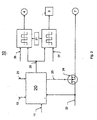
- the master control unit 10 has a logic module 20 which is connected to a power unit 21 of the vehicle. With him the current / voltage supply of the logic device 20 is ensured.
- the logic module 20 also receives a signal via the line 11, to the light switch of the vehicle connected.
- a ⁇ EC signal of a ⁇ EC circuit in the EC mirror 14 is fed to the logic module via a line 13 (FIG. 1). The formation of the ⁇ EC signal will be explained with reference to FIG. 3.
- the logic module 20 receives the signal from the switch of the rear fog lamp 7 via a further line 22.
- the logic module 20 controls via a line 23 a circuit breaker 24 with which the rear fog lamp 7 can be switched on and off automatically.
- the power switch 24 may be formed by a relay, by electronic components and the like.
- the signal coming via the line 22 is evaluated in the logic module 20. He sends via line 23 a corresponding signal to the circuit breaker. If the rear fog lamp 7 is turned on and approaches from behind a vehicle, then falls, as described above, the light emitted from the following vehicle light on the EC mirror 14. His sensor detects this striking light, evaluates it and sends via line 13 a corresponding signal to the logic module 20 of the master control unit 10.
- the logic module 20 actuates the circuit breaker 24 via the line 23 so that the rear fog lamp 7 is turned off.
- the logic module 20 With the logic module 20 also the brake light 3 and the flashing light 4 is operated in two different light levels. If the vehicle drives by day and the light switch of the vehicle is not switched on, then the brake light 3 and the flashing light 4 with operated a stronger light intensity (day position). If the vehicle drives in the dark and the light switch of the vehicle is switched on, a lower luminous intensity for the brake light 3 and the flashing light 4 is sufficient. Via the line 11, the logic module 20 is supplied in response to the position of the light switch, a corresponding signal. Accordingly, the received signals are evaluated by the logic device 20. At an output 25 is then in response to the position of the light switch on a low or high signal. A low signal is generated, for example, when the light switch of the vehicle is turned on.
- the height of the low and high signal can advantageously be set vehicle-specific.
- Corresponding actuating signals 26 and 27 are provided for this purpose.
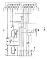
- FIG. 4 shows the two-level circuit of the master control unit 10, with which the bulbs of the two taillights 1 and 2 are operated in the manner described.
- the brake light 3 of the two Tail lights 1, 2 is preferably formed by LEDs, while the tail light 6, the flashing light 4, the reflector 5 and the rear fog lamp 7 of the two taillights 1, 2 are formed by incandescent bulbs.
- the two taillights 1, 2 are actuated by a switch 28 as a light switch, which is a rotary switch in the illustrated embodiment.
- the master control unit is provided with a flasher 31.
- a switch S1a, S1b Parallel to the dimmers 29, 30 is in each case a switch S1a, S1b. If these switches are closed, the respective dimmer 29, 30 is bridged.
- the rear fog light 7 is connected via a switch EC1. If the switch EC1 is open, the rear fog lamp 7 is switched off.
- a switch 32 In the line connection before the on-board voltage supply to the dimmer 29 is a switch 32 which is coupled to the brake of the vehicle. When the brake is applied, the switch 32 closes, so that the brake light 3 can light up.
- the light switch 28 is switched off. In this case, the switches S1a, S2a are closed, so that the dimmers 29, 30 are bridged. Therefore, when the brake or the turn signal of the vehicle is operated, the brake light 3 and the flashing light 4 illuminate with high light intensity. If the vehicle is driving at night, the vehicle lighting is switched on with the switch 28. This has the consequence that the two switches S1a, S1b are opened. About the dimmer 29, 30 then the brake light 3 and the flashing light 4 are supplied with a lower voltage or a lower current, so that they light up in a lower light intensity. The regulation of the individual lamp functions takes place here in the dimmers 29, 30 by means of a pulse width modulation.
- the switches EC1 and EC2 are switched by the sensor of the EC mirror 14.
- the switch EC1 is between the switch 28 and the rear fog lamp 7 in series. If the rear fog lamp 7 is turned on via the switch 28, then the rear fog lamp 7 is automatically turned off in the manner described when approaching the vehicle from behind an illuminated vehicle. The light emitted by it passes to the EC mirror 14, which evaluates the received light signals of the following vehicle in the manner described. By a corresponding switching signal, the switch EC1 is opened and thus the rear fog lamp 7 is turned off.
- FIG 3 shows an EC adapter 51, which is part of the sensor system of the EC mirror 14 and with which the rear fog lamp 7 is automatically switched off by differentiation.
- the circuit of the EC adapter 51 is connected to the power / voltage supply of the vehicle. For example, a voltage of 13.5 V is applied to the terminals 34, 35. The terminals 36, 37 are grounded. Via a terminal 38, the EC adapter 51 receives a signal from the EC mirror 14 or from its sensor system. This EC signal is supplied to an input 39 of a comparator 40. He compares this signal with a pending at its other input 41 comparison signal. At the output 42 of the comparator 40 is the difference signal, which is a flip-flop 43 is supplied.
- the input 41 of the comparator 40 is part of a comparator circuit 46 which has series-connected resistors 47 and 48 or 49 and 50, respectively.
- the resistors 47, 48 are connected in parallel to the resistors 49, 50.
- the resistance values are selected such that two different voltage values are present at the input 41, which in the exemplary embodiment are 0.3 V and 0.7 V, for example.
- the Flip-flop 43 is designed so that it outputs a signal from a voltage of 0.7 V in the exemplary embodiment.
- the flip-flop 43 In a voltage range between 0.3 V and 0.7 V, the flip-flop 43 holds the signal, while it outputs no signal at a voltage value of less than 0.3 V. Accordingly, the relay 45 is switched by the downstream transistor 44 for actuating the switches EC1 and EC2.
- the specified voltage values can also have other values. These two voltage values characterize the two different switching thresholds, in which the brake light 3 and the flashing light 4 are switched between light and dark operation, so that they light up in two different light intensities. About this differentiation, the brake light 3 and the flashing light 4 are supplied with the required voltage, so that they light up depending on environmental conditions in different strengths. In daytime driving the brake light 3 and the flashing light 4 with higher light intensity than at night driving.
- the switch EC2 comes into operation when the vehicle drives into a tunnel and is illuminated from behind by a subsequent vehicle.
- the EC mirror receives more light from the rear than from the front, so that via the terminal 38, a corresponding EC signal in the input 39 of the comparator 40 is supplied.
- the EC adapter 51 closes the switch EC2, attracting the downstream relay RE1a, b ( Figure 4) and opening the switches S1a, S1b.
- the dimmers 29, 30 are switched into the current path to the brake light 3 and the flashing light 4, so that it is ensured that they radiate with a reduced luminosity.
- glare of subsequent vehicles is reliably prevented by too intensely illuminated brake and flashing lights.
- FIG. 5 shows an example of the course of the EC signal voltage as a function of the time t.
- the two voltage levels of 0.3 V and 0.7 V mark the low and the high signal.
- the rear fog lamp 7 is turned on. This case occurs, as already stated, in normal operation when no vehicle follows. However, as soon as a vehicle approaches from the rear and its headlamp light appears on the EC mirror 14 of the vehicle ahead, the EC signal voltage increases. As soon as it has a value of more than 0.7 V, the rear fog lamp 7 is automatically switched off in the manner described, so that the following vehicle is not dazzled by the rear fog lamp. The rear fog lamp 7 remains switched off until the value of the EC signal voltage drops below 0.3 V again. Only then, in the manner described, the rear fog lamp 7 is automatically turned on again.
- the master and the slave control unit 10, 8 may be provided with so-called fail-safe circuits. Should a fault in the circuit or even a failure occur, the circuit is switched to the low level, so that the brake light 3 and the tail light 4 light up with reduced luminosity. This ensures in any case that the drivers of subsequent vehicles are not dazzled by these lights. Via another sensor in the EC mirror 14, automation of the light switch (day / night) is reliably ensured. Instead of the described pulse width modulation, the regulation of the individual lamp functions also via a resistance circuit, via a summation current controller or in particular via distributed current controller.
Landscapes
- Engineering & Computer Science (AREA)
- Mechanical Engineering (AREA)
- Lighting Device Outwards From Vehicle And Optical Signal (AREA)
- Arrangements Of Lighting Devices For Vehicle Interiors, Mounting And Supporting Thereof, Circuits Therefore (AREA)
Claims (14)
- Feu d'un véhicule, avec au moins un moyen lumineux (3, 4, 7) qui est relié à un circuit (10) et dont l'intensité lumineuse est réglable en fonction des conditions de luminosité extérieures, dans lequel le circuit comprend au moins un variateur (29, 30), avec lequel l'intensité lumineuse du moyen lumineux (3, 4, 7) peut être réduite, et dans lequel le circuit (10) est une unité de contrôle maître (10), caractérisé en ce que l'unité de contrôle maître (10) est suivie d'une unité de contrôle esclave (8), avec laquelle au moins un moyen lumineux (3, 4, 7) d'un deuxième feu (1, 2) peut être commandé.
- Feu selon la revendication 1, caractérisé en ce que l'intensité lumineuse du moyen lumineux (3, 4, 7) est réglable en fonction de la position d'un commutateur des phares (28) du véhicule.
- Feu selon la revendication 1 ou 2, caractérisé en ce que le variateur (29, 30) peut être court-circuité pour augmenter l'intensité lumineuse du moyen lumineux (3, 4).
- Feu selon la revendication 3, caractérisé en ce qu'un interrupteur (S1a, S1b) est monté en parallèle sur le variateur (29, 30), et est situé dans la ligne de raccordement d'un autre interrupteur (32, 33) vers le moyen lumineux (3, 4).
- Feu selon l'une quelconque des revendications 1 à 4, caractérisé en ce que le moyen lumineux est un feu stop (3).
- Feu selon l'une quelconque des revendications 1 à 4, caractérisé en ce que le moyen lumineux est un feu clignotant (4).
- Feu selon la revendication 5 ou 6, caractérisé en ce que le feu stop (3) et/ou le feu clignotant (4) est formé par des LED.
- Feu selon l'une quelconque des revendications 1 à 7, caractérisé en ce que le moyen lumineux (3, 4, 7) est relié à un détecteur d'un miroir intérieur électrochrome (14) du véhicule, lequel détecteur réduit au moins l'intensité lumineuse du moyen lumineux (3, 4, 7) lors de l'approche d'un véhicule suivant.
- Feu selon la revendication 8, caractérisé en ce que le moyen lumineux (7) est un feu antibrouillard arrière.
- Feu selon la revendication 9, caractérisé en ce que le détecteur du miroir intérieur électrochrome (14) coupe l'intensité lumineuse du feu antibrouillard arrière (7) lors de l'approche du véhicule suivant.
- Feu selon l'une quelconque des revendications 8 à 10, caractérisé en ce que le détecteur du miroir EC (14) est relié à un circuit de comparaison (46), qui compare la valeur réelle provenant du miroir EC (14) avec une valeur de référence.
- Feu selon la revendication 11, caractérisé en ce que le circuit de comparaison (46) comprend un comparateur (14), dont le signal de sortie est utilisé pour la commande du feu antibrouillard arrière (7).
- Feu selon la revendication 12, caractérisé en ce que le comparateur (40) est suivi d'un étage de bascule (43), qui allume ou éteint le feu antibrouillard arrière (7) en fonction du signal de sortie du comparateur (40).
- Feu selon la revendication 13, caractérisé en ce qu'au moins un interrupteur (EC1) peut être actionné avec l'étage de bascule (43) pour allumer ou éteindre le feu antibrouillard arrière (7).
Applications Claiming Priority (2)
| Application Number | Priority Date | Filing Date | Title |
|---|---|---|---|
| DE19714849 | 1997-04-10 | ||
| DE19714849A DE19714849A1 (de) | 1997-04-10 | 1997-04-10 | Leuchte, vorzugsweise Heckleuchte, eines Fahrzeuges, vorzugsweise eines Kraftfahrzeuges |
Publications (3)
| Publication Number | Publication Date |
|---|---|
| EP0870644A2 EP0870644A2 (fr) | 1998-10-14 |
| EP0870644A3 EP0870644A3 (fr) | 2000-03-08 |
| EP0870644B1 true EP0870644B1 (fr) | 2007-01-03 |
Family
ID=7826038
Family Applications (1)
| Application Number | Title | Priority Date | Filing Date |
|---|---|---|---|
| EP98103236A Expired - Lifetime EP0870644B1 (fr) | 1997-04-10 | 1998-02-25 | Feux de véhicule |
Country Status (4)
| Country | Link |
|---|---|
| US (1) | US6016035A (fr) |
| EP (1) | EP0870644B1 (fr) |
| DE (2) | DE19714849A1 (fr) |
| ES (1) | ES2276437T3 (fr) |
Families Citing this family (55)
| Publication number | Priority date | Publication date | Assignee | Title |
|---|---|---|---|---|
| US5910854A (en) | 1993-02-26 | 1999-06-08 | Donnelly Corporation | Electrochromic polymeric solid films, manufacturing electrochromic devices using such solid films, and processes for making such solid films and devices |
| US5668663A (en) | 1994-05-05 | 1997-09-16 | Donnelly Corporation | Electrochromic mirrors and devices |
| US6891563B2 (en) * | 1996-05-22 | 2005-05-10 | Donnelly Corporation | Vehicular vision system |
| US6587573B1 (en) * | 2000-03-20 | 2003-07-01 | Gentex Corporation | System for controlling exterior vehicle lights |
| US8294975B2 (en) | 1997-08-25 | 2012-10-23 | Donnelly Corporation | Automotive rearview mirror assembly |
| US6326613B1 (en) | 1998-01-07 | 2001-12-04 | Donnelly Corporation | Vehicle interior mirror assembly adapted for containing a rain sensor |
| US6172613B1 (en) | 1998-02-18 | 2001-01-09 | Donnelly Corporation | Rearview mirror assembly incorporating vehicle information display |
| US6124886A (en) * | 1997-08-25 | 2000-09-26 | Donnelly Corporation | Modular rearview mirror assembly |
| US6445287B1 (en) | 2000-02-28 | 2002-09-03 | Donnelly Corporation | Tire inflation assistance monitoring system |
| US8288711B2 (en) | 1998-01-07 | 2012-10-16 | Donnelly Corporation | Interior rearview mirror system with forwardly-viewing camera and a control |
| US6477464B2 (en) | 2000-03-09 | 2002-11-05 | Donnelly Corporation | Complete mirror-based global-positioning system (GPS) navigation solution |
| US6329925B1 (en) * | 1999-11-24 | 2001-12-11 | Donnelly Corporation | Rearview mirror assembly with added feature modular display |
| US6693517B2 (en) | 2000-04-21 | 2004-02-17 | Donnelly Corporation | Vehicle mirror assembly communicating wirelessly with vehicle accessories and occupants |
| US6158882A (en) * | 1998-06-30 | 2000-12-12 | Emteq, Inc. | LED semiconductor lighting system |
| DE19901413C2 (de) * | 1999-01-16 | 2002-12-05 | Helmut Haf | Elektronik eines Fahrzeuges, vorzugsweise eines Kraftfahrzeuges |
| DE19945775B4 (de) * | 1999-09-24 | 2005-05-25 | Audi Ag | Leuchtenanordnung als Heckleuchte für ein Kraftfahrzeug |
| US7049761B2 (en) | 2000-02-11 | 2006-05-23 | Altair Engineering, Inc. | Light tube and power supply circuit |
| US7370983B2 (en) | 2000-03-02 | 2008-05-13 | Donnelly Corporation | Interior mirror assembly with display |
| US7167796B2 (en) * | 2000-03-09 | 2007-01-23 | Donnelly Corporation | Vehicle navigation system for use with a telematics system |
| AU2001243285A1 (en) * | 2000-03-02 | 2001-09-12 | Donnelly Corporation | Video mirror systems incorporating an accessory module |
| US7255451B2 (en) | 2002-09-20 | 2007-08-14 | Donnelly Corporation | Electro-optic mirror cell |
| US7581859B2 (en) | 2005-09-14 | 2009-09-01 | Donnelly Corp. | Display device for exterior rearview mirror |
| WO2002062623A2 (fr) * | 2001-01-23 | 2002-08-15 | Donnelly Corporation | Systeme d'eclairage ameliore destine a un vehicule |
| DE10154983A1 (de) * | 2001-11-08 | 2003-05-22 | Opel Adam Ag | Blinkanlage für ein Kraftfahrzeug |
| US6641294B2 (en) | 2002-03-22 | 2003-11-04 | Emteq, Inc. | Vehicle lighting assembly with stepped dimming |
| US6918674B2 (en) | 2002-05-03 | 2005-07-19 | Donnelly Corporation | Vehicle rearview mirror system |
| AU2003237424A1 (en) * | 2002-06-06 | 2003-12-22 | Donnelly Corporation | Interior rearview mirror system with compass |
| US7329013B2 (en) | 2002-06-06 | 2008-02-12 | Donnelly Corporation | Interior rearview mirror system with compass |
| US7310177B2 (en) * | 2002-09-20 | 2007-12-18 | Donnelly Corporation | Electro-optic reflective element assembly |
| WO2004103772A2 (fr) | 2003-05-19 | 2004-12-02 | Donnelly Corporation | Assemblage de retroviseur pour vehicule |
| AU2003278863A1 (en) | 2002-09-20 | 2004-04-08 | Donnelly Corporation | Mirror reflective element assembly |
| US7446924B2 (en) * | 2003-10-02 | 2008-11-04 | Donnelly Corporation | Mirror reflective element assembly including electronic component |
| US7308341B2 (en) | 2003-10-14 | 2007-12-11 | Donnelly Corporation | Vehicle communication system |
| DE102004002334B4 (de) * | 2004-01-16 | 2006-01-26 | Adam Opel Ag | Steuerschaltung für die Beleuchtungsanlage eines Kraftfahrzeuges |
| ES2245870B1 (es) * | 2004-02-13 | 2007-07-16 | Marcelino Hervas De La Torre | Dispositivo regulador luz antiniebla trasera. |
| DE102004022555B4 (de) * | 2004-05-07 | 2006-04-06 | Siemens Ag | Vorrichtung und Verfahren zum Synchronisieren einer Blinkerfrequenz mit einer Zentralblinkfrequenz |
| ATE517368T1 (de) | 2005-05-16 | 2011-08-15 | Donnelly Corp | Fahrzeugspiegelanordnung mit zeichen am reflektierenden teil |
| CN101535087B (zh) | 2005-11-01 | 2013-05-15 | 唐纳利公司 | 具有显示装置的内部后视镜 |
| DE102006008276B4 (de) * | 2006-02-22 | 2018-02-15 | Continental Automotive Gmbh | Verfahren und Steuergerät zum Steuern einer Leistung einer Leuchte |
| ITBO20070181A1 (it) * | 2007-03-15 | 2008-09-16 | Luca Gurioli | Metodo e dispositivo per il controllo dei fari retronebbia dei veicoli |
| DE102007017170A1 (de) * | 2007-04-12 | 2008-10-16 | GM Global Technology Operations, Inc., Detroit | Selbstabblendender Spiegel in einem Kraftfahrzeug |
| DE102008005314A1 (de) * | 2008-01-21 | 2009-07-23 | Robert Bosch Gmbh | Verfahren und Vorrichtung zum Erfassen eines vorbeifahrenden Fahrzeuges bei Dunkelheit |
| US8154418B2 (en) | 2008-03-31 | 2012-04-10 | Magna Mirrors Of America, Inc. | Interior rearview mirror system |
| US9487144B2 (en) | 2008-10-16 | 2016-11-08 | Magna Mirrors Of America, Inc. | Interior mirror assembly with display |
| US9315146B2 (en) * | 2010-04-13 | 2016-04-19 | Kory Patrick Purks | Vehicle turn signalling apparatuses with laser devices, light projection circuits, and related electromechanical actuators |
| DE102010044800A1 (de) * | 2010-09-09 | 2012-03-15 | Bpw Bergische Achsen Kg | Fahrzeugbeleuchtungssystem mit einer Ausweichschaltung |
| ITPV20110004A1 (it) * | 2011-02-08 | 2012-08-09 | Luigi Buonanno | Retrofaro antinebbia di sicurezza per autoveicolo |
| DE102012020272A1 (de) * | 2012-10-17 | 2014-04-17 | Claudia Goschau | Steuergerät/Schaltkreis zur Dimmung der Bremslichtfunktion an Kraftfahrzeugen |
| KR101703147B1 (ko) * | 2013-07-08 | 2017-02-06 | 한국전자통신연구원 | 밝기 조절 및 가시광 무선통신이 가능한 차량 후미등 제어 장치 및 방법 |
| DE102016205683A1 (de) * | 2016-04-06 | 2017-10-12 | Bayerische Motoren Werke Aktiengesellschaft | Fahrzeugscheinwerfersystem |
| US10000157B2 (en) * | 2016-04-29 | 2018-06-19 | Faraday&Future Inc. | Controlling dimming of mirrors or displays using dual-function lighting |
| FR3056679B1 (fr) * | 2016-09-27 | 2020-09-04 | Valeo Vision | Dispositif avec modules lumineux maitre et esclave |
| DE102016224147B4 (de) | 2016-12-05 | 2022-04-28 | Audi Ag | System zur distanz- und geschwindigkeitssensitiven Steuerung der Helligkeit eines von einer Heckleuchte eines Ego-Fahrzeugs abgestrahlten Lichts |
| FR3106395A1 (fr) * | 2020-01-21 | 2021-07-23 | Psa Automobiles Sa | Méthodes et systèmes de commande des feux de brouillard arrière |
| JP7590243B2 (ja) * | 2021-03-25 | 2024-11-26 | 株式会社Subaru | リアフォグランプ制御装置 |
Family Cites Families (11)
| Publication number | Priority date | Publication date | Assignee | Title |
|---|---|---|---|---|
| US2827594A (en) * | 1954-09-02 | 1958-03-18 | Rabinow Jacob | Color discriminating headlight dimmer |
| US2944188A (en) * | 1958-04-10 | 1960-07-05 | Gen Motors Corp | Automatic light controlled headlamp means |
| US4211955A (en) * | 1978-03-02 | 1980-07-08 | Ray Stephen W | Solid state lamp |
| DE3040714A1 (de) * | 1980-10-29 | 1982-05-27 | Rolf Dipl.-Ing. 5600 Wuppertal Rychzynski | Helligkeitsgeregeltes bremslicht von kraftfahrzeugen |
| DE3416164A1 (de) * | 1984-05-02 | 1985-11-21 | Christian 5630 Remscheid Hegermann | Einrichtung zur ueberwachung des aussenlichtes ob fahrzeuglicht benoetigt wird, mit gleichzeitiger kontrolle des eingeschalteten fahrzeuglichtes auf funktion und lichtintensitaet |
| JPH0416447Y2 (fr) * | 1985-07-22 | 1992-04-13 | ||
| US4665321A (en) * | 1985-08-14 | 1987-05-12 | Kwangling Chang | Automatic control system for automobile lights |
| US4841198A (en) * | 1987-10-19 | 1989-06-20 | Nartron Corporation | Head lamp control method and apparatus, with PWM output regulation |
| JP2957079B2 (ja) * | 1994-03-03 | 1999-10-04 | 矢崎総業株式会社 | 照明調光器 |
| EP0693397B1 (fr) * | 1994-07-19 | 2002-09-11 | Donnelly Corporation | Système de rétroviseur automatique à allumage automatique des phares |
| DE19615808A1 (de) * | 1996-04-20 | 1997-10-23 | Reitter & Schefenacker Gmbh | Rückleuchte eines Fahrzeuges, vorzugsweise eines Kraftfahrzeuges |
-
1997
- 1997-04-10 DE DE19714849A patent/DE19714849A1/de not_active Ceased
-
1998
- 1998-02-25 ES ES98103236T patent/ES2276437T3/es not_active Expired - Lifetime
- 1998-02-25 DE DE59813861T patent/DE59813861D1/de not_active Expired - Lifetime
- 1998-02-25 EP EP98103236A patent/EP0870644B1/fr not_active Expired - Lifetime
- 1998-04-10 US US09/059,059 patent/US6016035A/en not_active Expired - Lifetime
Also Published As
| Publication number | Publication date |
|---|---|
| EP0870644A3 (fr) | 2000-03-08 |
| EP0870644A2 (fr) | 1998-10-14 |
| DE19714849A1 (de) | 1998-10-15 |
| ES2276437T3 (es) | 2007-06-16 |
| DE59813861D1 (de) | 2007-02-15 |
| US6016035A (en) | 2000-01-18 |
Similar Documents
| Publication | Publication Date | Title |
|---|---|---|
| EP0870644B1 (fr) | Feux de véhicule | |
| EP0802081B1 (fr) | Feux arrières pour véhicule | |
| EP1950089B1 (fr) | Eclairage de véhicule | |
| DE102004045435A1 (de) | Überwachung der Funktion von Glühlampen oder LED-Leuchten in Kraftfahrzeugen | |
| EP2067660A2 (fr) | Procédé destiné à la réduction de l'émission de clarté de lampes et dispositif destiné à la réduction de la clarté de lampes dans des véhicules | |
| EP1818214B1 (fr) | Feu, en particulier feu arrière d'un véhicule, de préférence d'un véhicule automobile | |
| DE102018200334A1 (de) | Fahrtrichtungsanzeiger, insbesondere mit Wischeffekt und Warnblinkfunktion | |
| DE102012020428A1 (de) | Kraftfahrzeug-Lichtanlage und entsprechendes Betriebsverfahren | |
| DE19953447A1 (de) | Steuereinrichtung für Bremsleuchten | |
| DE102008031078B4 (de) | Fahrzeugleuchte | |
| DE4035956A1 (de) | Schaltungseinrichtung fuer eine kraftfahrzeugleuchte | |
| DE3724916A1 (de) | Kraftfahrzeug fuer anhaengerbetrieb mit heckleuchten-ueberwachung | |
| DE102011051152A1 (de) | Verfahren zum Betrieb einer Leuchte sowie Leuchte für ein Fahrzeug | |
| DE102011006423A1 (de) | Lichtsteuereinrichtung für ein Kraftfahrzeug und Verfahren zum Steuern der Funktion eines Blinklichts und eines Tagfahrlichts | |
| DE3436391A1 (de) | Verfahren zur betaetigung der frontseitigen beleuchtungsanlage eines kraftfahrzeuges und schaltungsanordnung zur durchfuehrung des verfahrens | |
| DE4408959C1 (de) | Schaltung für eine Anlage mit einem intermittierend betreibbaren Element, insbesondere eine Kraftfahrzeug-Warnblinkanlage | |
| DE1530678A1 (de) | Beleuchtungs- und Blinkanlage fuer Kraftfahrzeuge | |
| DE1954025A1 (de) | Vorrichtung zur AEnderung der Intensitaet von Signallampen,insbesondere Fahrzeuglampen | |
| EP4051955B1 (fr) | Procédé de fonctionnement d'un feu arrière d'un véhicule à moteur et véhicule automobile | |
| EP3399840A1 (fr) | Commande d'au moins un moyen d'éclairage d'un phare de véhicule en fonction d'une grandeur électrique pouvant être fournie à une borne de phare de véhicule d'un véhicule | |
| EP4415482B1 (fr) | Moyen d'éclairage comprenant plusieurs del comme sources lumineuses pour deux fonctions lumineuses avec intersection des faces lumineuses prévues pour les réaliser (bi-fonction) et feu de véhicule équipé de celui-ci | |
| EP3363685A1 (fr) | Phare de véhicule et son procédé de fonctionnement | |
| DE102013113007A1 (de) | Steuereinrichtung für Außenlichteinheiten von Fahrzeugen | |
| DE102010000312B3 (de) | Vorrichtung zum Betreiben von Anhängerleuchten | |
| DE69614999T2 (de) | Verfahren und einrichtung zur steuerung eines fahrzeugscheinwerfers |
Legal Events
| Date | Code | Title | Description |
|---|---|---|---|
| PUAI | Public reference made under article 153(3) epc to a published international application that has entered the european phase |
Free format text: ORIGINAL CODE: 0009012 |
|
| AK | Designated contracting states |
Kind code of ref document: A2 Designated state(s): BE DE ES FR GB IT LU NL SE |
|
| AX | Request for extension of the european patent |
Free format text: AL;LT;LV;MK;RO;SI |
|
| PUAL | Search report despatched |
Free format text: ORIGINAL CODE: 0009013 |
|
| AK | Designated contracting states |
Kind code of ref document: A3 Designated state(s): AT BE CH DE DK ES FI FR GB GR IE IT LI LU MC NL PT SE |
|
| AX | Request for extension of the european patent |
Free format text: AL;LT;LV;MK;RO;SI |
|
| 17P | Request for examination filed |
Effective date: 20000711 |
|
| AKX | Designation fees paid |
Free format text: BE DE ES FR GB IT LU NL SE |
|
| 17Q | First examination report despatched |
Effective date: 20031103 |
|
| GRAP | Despatch of communication of intention to grant a patent |
Free format text: ORIGINAL CODE: EPIDOSNIGR1 |
|
| GRAS | Grant fee paid |
Free format text: ORIGINAL CODE: EPIDOSNIGR3 |
|
| RAP1 | Party data changed (applicant data changed or rights of an application transferred) |
Owner name: SCHEFENACKER VISION SYSTEMS GERMANY GMBH |
|
| GRAA | (expected) grant |
Free format text: ORIGINAL CODE: 0009210 |
|
| AK | Designated contracting states |
Kind code of ref document: B1 Designated state(s): BE DE ES FR GB IT LU NL SE |
|
| PG25 | Lapsed in a contracting state [announced via postgrant information from national office to epo] |
Ref country code: NL Free format text: LAPSE BECAUSE OF FAILURE TO SUBMIT A TRANSLATION OF THE DESCRIPTION OR TO PAY THE FEE WITHIN THE PRESCRIBED TIME-LIMIT Effective date: 20070103 |
|
| REG | Reference to a national code |
Ref country code: GB Ref legal event code: FG4D Free format text: NOT ENGLISH |
|
| REF | Corresponds to: |
Ref document number: 59813861 Country of ref document: DE Date of ref document: 20070215 Kind code of ref document: P |
|
| PGFP | Annual fee paid to national office [announced via postgrant information from national office to epo] |
Ref country code: GB Payment date: 20070327 Year of fee payment: 10 |
|
| PG25 | Lapsed in a contracting state [announced via postgrant information from national office to epo] |
Ref country code: SE Free format text: LAPSE BECAUSE OF FAILURE TO SUBMIT A TRANSLATION OF THE DESCRIPTION OR TO PAY THE FEE WITHIN THE PRESCRIBED TIME-LIMIT Effective date: 20070403 |
|
| GBT | Gb: translation of ep patent filed (gb section 77(6)(a)/1977) |
Effective date: 20070329 |
|
| PGFP | Annual fee paid to national office [announced via postgrant information from national office to epo] |
Ref country code: ES Payment date: 20070425 Year of fee payment: 10 |
|
| REG | Reference to a national code |
Ref country code: ES Ref legal event code: FG2A Ref document number: 2276437 Country of ref document: ES Kind code of ref document: T3 |
|
| ET | Fr: translation filed | ||
| NLV1 | Nl: lapsed or annulled due to failure to fulfill the requirements of art. 29p and 29m of the patents act | ||
| PLBE | No opposition filed within time limit |
Free format text: ORIGINAL CODE: 0009261 |
|
| STAA | Information on the status of an ep patent application or granted ep patent |
Free format text: STATUS: NO OPPOSITION FILED WITHIN TIME LIMIT |
|
| 26N | No opposition filed |
Effective date: 20071005 |
|
| BERE | Be: lapsed |
Owner name: SCHEFENACKER VISION SYSTEMS GERMANY G.M.B.H. Effective date: 20070228 |
|
| PG25 | Lapsed in a contracting state [announced via postgrant information from national office to epo] |
Ref country code: BE Free format text: LAPSE BECAUSE OF NON-PAYMENT OF DUE FEES Effective date: 20070228 |
|
| GBPC | Gb: european patent ceased through non-payment of renewal fee |
Effective date: 20080225 |
|
| REG | Reference to a national code |
Ref country code: ES Ref legal event code: FD2A Effective date: 20080226 |
|
| PG25 | Lapsed in a contracting state [announced via postgrant information from national office to epo] |
Ref country code: GB Free format text: LAPSE BECAUSE OF NON-PAYMENT OF DUE FEES Effective date: 20080225 |
|
| PG25 | Lapsed in a contracting state [announced via postgrant information from national office to epo] |
Ref country code: ES Free format text: LAPSE BECAUSE OF NON-PAYMENT OF DUE FEES Effective date: 20080226 |
|
| PG25 | Lapsed in a contracting state [announced via postgrant information from national office to epo] |
Ref country code: LU Free format text: LAPSE BECAUSE OF NON-PAYMENT OF DUE FEES Effective date: 20070225 |
|
| PGFP | Annual fee paid to national office [announced via postgrant information from national office to epo] |
Ref country code: FR Payment date: 20120227 Year of fee payment: 15 |
|
| PGFP | Annual fee paid to national office [announced via postgrant information from national office to epo] |
Ref country code: DE Payment date: 20120221 Year of fee payment: 15 |
|
| PGFP | Annual fee paid to national office [announced via postgrant information from national office to epo] |
Ref country code: IT Payment date: 20120227 Year of fee payment: 15 |
|
| REG | Reference to a national code |
Ref country code: FR Ref legal event code: ST Effective date: 20131031 |
|
| REG | Reference to a national code |
Ref country code: DE Ref legal event code: R119 Ref document number: 59813861 Country of ref document: DE Effective date: 20130903 |
|
| PG25 | Lapsed in a contracting state [announced via postgrant information from national office to epo] |
Ref country code: IT Free format text: LAPSE BECAUSE OF NON-PAYMENT OF DUE FEES Effective date: 20130225 |
|
| PG25 | Lapsed in a contracting state [announced via postgrant information from national office to epo] |
Ref country code: DE Free format text: LAPSE BECAUSE OF NON-PAYMENT OF DUE FEES Effective date: 20130903 Ref country code: FR Free format text: LAPSE BECAUSE OF NON-PAYMENT OF DUE FEES Effective date: 20130228 |