EP0872211A1 - Hybrid-Sensor zur Wieder-Erkennung von Gewebe-Typen - Google Patents
Hybrid-Sensor zur Wieder-Erkennung von Gewebe-TypenInfo
- Publication number
- EP0872211A1 EP0872211A1 EP97306307A EP97306307A EP0872211A1 EP 0872211 A1 EP0872211 A1 EP 0872211A1 EP 97306307 A EP97306307 A EP 97306307A EP 97306307 A EP97306307 A EP 97306307A EP 0872211 A1 EP0872211 A1 EP 0872211A1
- Authority
- EP
- European Patent Office
- Prior art keywords
- tissue
- die
- detector
- identifying
- probe
- Prior art date
- Legal status (The legal status is an assumption and is not a legal conclusion. Google has not performed a legal analysis and makes no representation as to the accuracy of the status listed.)
- Granted
Links
- 239000000523 sample Substances 0.000 title claims abstract description 40
- 230000003287 optical effect Effects 0.000 claims abstract description 26
- 230000005855 radiation Effects 0.000 claims description 22
- 238000005259 measurement Methods 0.000 claims description 19
- 230000004044 response Effects 0.000 claims description 14
- 239000002775 capsule Substances 0.000 claims description 4
- 229910052751 metal Inorganic materials 0.000 claims description 4
- 239000002184 metal Substances 0.000 claims description 4
- 230000008878 coupling Effects 0.000 claims description 3
- 238000010168 coupling process Methods 0.000 claims description 3
- 238000005859 coupling reaction Methods 0.000 claims description 3
- 230000000694 effects Effects 0.000 claims description 3
- 210000001835 viscera Anatomy 0.000 claims description 3
- 238000012937 correction Methods 0.000 claims description 2
- 238000006880 cross-coupling reaction Methods 0.000 claims 1
- 239000000835 fiber Substances 0.000 abstract description 5
- 239000000758 substrate Substances 0.000 abstract description 5
- 230000005693 optoelectronics Effects 0.000 description 10
- 230000004888 barrier function Effects 0.000 description 7
- 238000002955 isolation Methods 0.000 description 7
- 230000035945 sensitivity Effects 0.000 description 5
- 238000013461 design Methods 0.000 description 4
- 206010028980 Neoplasm Diseases 0.000 description 3
- 230000008901 benefit Effects 0.000 description 3
- 201000011510 cancer Diseases 0.000 description 3
- 238000005516 engineering process Methods 0.000 description 3
- 238000000034 method Methods 0.000 description 3
- 238000012986 modification Methods 0.000 description 3
- 230000004048 modification Effects 0.000 description 3
- 239000013307 optical fiber Substances 0.000 description 3
- 230000035515 penetration Effects 0.000 description 3
- 238000001514 detection method Methods 0.000 description 2
- 238000007667 floating Methods 0.000 description 2
- 230000036541 health Effects 0.000 description 2
- KTXUOWUHFLBZPW-UHFFFAOYSA-N 1-chloro-3-(3-chlorophenyl)benzene Chemical compound ClC1=CC=CC(C=2C=C(Cl)C=CC=2)=C1 KTXUOWUHFLBZPW-UHFFFAOYSA-N 0.000 description 1
- 208000004210 Pressure Ulcer Diseases 0.000 description 1
- 230000002159 abnormal effect Effects 0.000 description 1
- 230000005856 abnormality Effects 0.000 description 1
- 238000004458 analytical method Methods 0.000 description 1
- 210000001367 artery Anatomy 0.000 description 1
- 210000003679 cervix uteri Anatomy 0.000 description 1
- 230000008859 change Effects 0.000 description 1
- 230000006378 damage Effects 0.000 description 1
- 238000005286 illumination Methods 0.000 description 1
- 230000001771 impaired effect Effects 0.000 description 1
- 230000006872 improvement Effects 0.000 description 1
- 208000014674 injury Diseases 0.000 description 1
- 230000007794 irritation Effects 0.000 description 1
- 210000003734 kidney Anatomy 0.000 description 1
- 210000004072 lung Anatomy 0.000 description 1
- 238000004519 manufacturing process Methods 0.000 description 1
- 229910000510 noble metal Inorganic materials 0.000 description 1
- 238000012856 packing Methods 0.000 description 1
- 230000037361 pathway Effects 0.000 description 1
- 230000002085 persistent effect Effects 0.000 description 1
- 230000000704 physical effect Effects 0.000 description 1
- 239000011347 resin Substances 0.000 description 1
- 229920005989 resin Polymers 0.000 description 1
- 238000005070 sampling Methods 0.000 description 1
- 210000002784 stomach Anatomy 0.000 description 1
- 239000013589 supplement Substances 0.000 description 1
- 230000000451 tissue damage Effects 0.000 description 1
- 231100000827 tissue damage Toxicity 0.000 description 1
- 230000008733 trauma Effects 0.000 description 1
- 210000003462 vein Anatomy 0.000 description 1
- 230000000007 visual effect Effects 0.000 description 1
Images


Classifications
-
- A—HUMAN NECESSITIES
- A61—MEDICAL OR VETERINARY SCIENCE; HYGIENE
- A61B—DIAGNOSIS; SURGERY; IDENTIFICATION
- A61B5/00—Measuring for diagnostic purposes; Identification of persons
- A61B5/0059—Measuring for diagnostic purposes; Identification of persons using light, e.g. diagnosis by transillumination, diascopy, fluorescence
- A61B5/0082—Measuring for diagnostic purposes; Identification of persons using light, e.g. diagnosis by transillumination, diascopy, fluorescence adapted for particular medical purposes
- A61B5/0084—Measuring for diagnostic purposes; Identification of persons using light, e.g. diagnosis by transillumination, diascopy, fluorescence adapted for particular medical purposes for introduction into the body, e.g. by catheters
Definitions
- the present invention relates to probes and a method for identifying different tissue types including those displaying modifications involving pre-cancerous and cancerous stages, diseased tissue, and those that are in a transitional stage.
- the identification of different tissue types is provided via a set of measurements of the tissue's physical properties and in particular the optical and electrical properties of the tissue.
- the medical profession often needs to have an objective assessment of the health of the tissue of a patient.
- the patient may have suffered tissue damage as a result of accidental or deliberate trauma as for example during a surgical operation.
- the patient may also be suffering some other more persistent irritation as a result, for example, of being confined to bed which can lead to bed sores. It is valuable for a medical practitioner to be able to tell in advance the type of treatment that would benefit the patient.
- the previous disclosure described an apparatus that employed optical fibre technology for performing the optical measurements. While this technology is effective, a good deal of manual labor is involved in building a probe to that design. The level of skill required precludes the manufacture of the device on a large scale at a low price for a mass market.
- the fibre-based device also has potential problems with temperature sensitivity which cannot be avoided with optical fibers, particularly when they are bent and the temperature sensitivity cannot readily be compensated.
- the present invention concerns a hybrid probe for both electrical and optical measurements in which the optical pathway and the optical sensors comprise elements located within a hybrid chip structure that is compact.
- This invention overcomes the problems inherent in earlier designs of probes by siting the opto-electronics components in a high density array at the working face of the probe. This is achieved by employing bare opto-electronic dice rather than packaged components and mounting these in close proximity to each other in an optimally designed chamber. Appropriate electrical connections are made to these dice which are powered from electronics in the handle of the probe.
- an apparatus for identifying different tissue types including those displaying modifications involving precancerous or cancerous activity, said apparatus comprising a probe having one end shaped to face said tissue and having at least one radiation source towards the end of the probe and a detector for that radiation and a comparator to compare the measured received radiation with known values to thereby identify the tissue type.
- the apparatus may also include at least one electrode to apply electrical signals to the tissue and electrical means to measure the resulting electrical response by said tissue.
- a comparator is employed to compare the electrical and optical signals with a catalogue of known tissue type signals to identify the tissue.
- the hybrid probe is designed to examine areas of tissue having a diameter of the order of 2 mm, which requires that photodiode detectors be placed in close juxtaposition with light emitters yet optically isolated so that light signals do not pass directly from an emitter to a detector without intervention (i.e. backscattering) by the tissue under examination.
- the metal barriers also shield the detector circuitry from electrical interference carried by current pulses that must be applied to the LEDs to induce them to emit light.
- the metal barrier may be left floating or grounded, but can also serve an additional role as an electrode for making electrical measurements to replace or supplement the two or three noble metal electrodes adjacent to the hybrid circuit normally used for the electrical measurements to be made on the tissue.
- the hybrid structure provides a preamplifier in close proximity to the photodiodes to amplify the small current from the photodiode detectors and feed it to the electronics in the handle of the probe and from there to the analysis circuitry.
- the fiber-based probe is temperature sensitive. This temperature sensitivity often occurs at bends in the fiber. It is often not practical to measure these temperatures so compensation is difficult to achieve. A change in temperature at the tip of the probe is likely to occur when the probe is brought into contact with the tissue of a warm blooded being.
- the subject of this invention overcomes the forms of temperature sensitivity arising from the fibers.
- the radiation output of LEDs is also temperature sensitive but for precise measurements can be compensated by using a characteristic of the LED to determine its own temperature.
- the bandgap potential of LEDs is a known function of temperature, allowing the temperature to be determined by applying a known current to the diode and measuring the potential across it. This can then be used to correct for the output of the LED using established equations thereby compensating for the changed radiation emission caused by temperature changes.
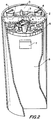
- Figure 1 is an illustration of the layout of the tip of the probe as seen in perspective showing only optical components.
- Figure 2 is an illustration of another embodiment that includes electrodes in the probe tip.
- Figure 3 is an illustration in section of another embodiment of the invention having a multilayered substrate running along at least a portion of the length of the probe.
- Figure 4 is an end view of the multilayered substrate embodiment from the probe tip end.
- Figure 5 is a perspective view of the multilayered substrate embodiment.
- the invention provides effective devices where three or more electrodes are sited within the small dimensions of the assembly enabling electrical measurements to be made on essentially the same area of tissue as that measured optically.
- the invention provides a novel design layout solving these problems.
- the layout described achieves the needed isolation of the input and output optical signals and the corresponding emitter driving currents from minuscule detector currents. This isolation is a critical requirement since the optical losses involved in this method of measurement are great and effective shielding is vital. The opportunity for signal leakage is ever present since the drive currents to the LEDs are many orders of magnitude greater than the detector currents. Isolation of the electrical measurements from the optical ones is conveniently achieved by performing the measurements sequentially but nearly simultaneously rather than precisely simultaneously.
- the invention does not reside entirely in any particular layout.
- Other layouts of the components are feasible if the principles embodied in this invention are adhered to. These principles concern the isolation of elements and the maintaining of active elements in close, but suitably spaced proximity to the tissue under examination. These principles are described in part by the ends to be accomplished by suitable layouts and guidance is further given by specifying preferred layouts.
- the barrier can be used as an electrode for the purposes of tissue electrical measurements. By this means the electrical measurement can be placed in the center of the region of optical measurement, a desirable but not an essential feature.
- Figure 1 shows a perspective view of the probe tip with the placement of the opto-electronic components clearly shown.
- This probe is useful to detect the onset of precancer or cancer within the endocervical canal or os in addition to making measurements on the outer parts of the cervix.
- the hybrid probe has a cylindrical shape with a diameter of about 3 mm.
- the radiation sources 1 in this case are LEDs and three are shown in this assembly, located within a space 5 at the tip of the probe. They are mounted on a substrate 9 along with the other components.
- the barrier 2 divides the assembly into two chambers. This barrier must be electrically conductive to provide the needed electrical shielding. It can be grounded or left floating. In the far side chamber is located the radiation detector 3.
- FIG. 2 illustrates an embodiment of the invention that includes electrodes.
- electrodes 4 have been included in the assembly to enable electrical measurements to be made. Three are shown but the number can vary depending on other factors.
- the electrodes illustrated are circular but they may be of other dimensions.
- kidney-shaped electrodes offer advantages since they can be of greater area than by limiting the shape to circular.
- An advantage in adopting the kidney shape is to achieve the maximum possible electrode area without compromising the optical performance or the electrical resolution. Larger electrodes by their nature produce less noisy data because they are sampling a larger area of tissue which is naturally less variable than a smaller area.
- the space 5 is typically filled with a transparent resin to hold the components in position and to protect them from damage.
- the assembly is mounted in a tube 6 which forms part of the completed probe.
- An amplifier 7 boosts the signal from the detector 3 so that it can be conveyed back to the controller.
- the amplifier is mounted on a circuit board 8 which holds other circuits involved in driving the LEDs and electrodes.
- a critical feature of this arrangement arises from the need to take special care with the shielding of the wiring from the detector 3 to its amplifier 7 .
- the currents flowing in this wire may be of the order of nanoamperes.
- the drive current to the nearby LEDs may be as high as 100 milliamperes. The ratio of these currents is huge so shielding is vital.
- the patient's body may have substantial voltage signals present because of adjacent wiring or other electrical equipment being operated nearby
- the detector circuit must therefore be shielded from this source of interference as well. This is achieved by the use, for example, of multilayer circuit boards 8 to convey the signals.
- the disposition of the signals flowing in the tracks on these boards must be chosen carefully to avoid unwanted capacitive or electromagnetic coupling.
- the optical layout needs to be planned because of the conflicting demands made on it.
- the radiation signal reaching the tissue needs to reach a level sufficient to compete with the ambient light level being employed for the operator's visual needs.
- LEDs have limited light output so as much as possible of this output radiation needs to be available to illuminate the tissue. To achieve this the LEDs 1 are placed as close as possible to the tissue. If, in fact, the efficiency of LEDs continues to improve, the above consideration may become less of a problem in the future.
- the distance from the top of the LEDs to the tissue There are two limits to how small the distance from the top of the LEDs to the tissue can be made. The first of these is the need to accommodate the bond wires 17 from the top of the LEDs which tends to loop upward from the surface of the LED die. The second arises from optical considerations. It is important to control the direction and angle of the illumination of the tissue surface so that probes behave consistently. If the distance between the opto-electronics and the tissue varies, the sensitivity of the device will vary. Tissue recognition will thereby be impaired. The distance from the LEDs to the tissue surface should therefore be kept large enough that assembly tolerances do not lead to uncontrolled variability between probes. Since the position and size of the LED top surface can typically be controlled to within plus or minus 25 micrometers, this uncertainty should not be more than, say, 5% of the LED to surface distance. That distance should therefore be not less than 0. 5 millimeter.
- the lateral placement of the dice is similarly controllable to only 25 micrometers so this needs to be factored in to the geometric considerations. More deeply placed dice will be less sensitive to errors in placement.
- the lateral placement also affects the diagnostic ability of the device by modifying the depth of penetration of the radiation prior to its return to the detector. It is important therefore that the placement be chosen to achieve the desired depth of penetration bearing in mind the tolerances on the accuracy that can be maintained. In general the closer the opto-electronics components 1 and 3 are to the barrier 2 the smaller the depth of penetration.
- Figure 3 shows another embodiment of the invention.
- the optoelectronics components 1 and 3 are mounted on opposite sides of a multilayer PCB 11 .
- the light emitters 1 are on one side while the detector 3 is on the other.
- the detector is connected to the amplifier 7 which is mounted back from the tip.
- Electrodes 13, 14 and 15 are situated around the opto-electronics and electrodes 13 and 14 perform the additional duty of acting as radiation reflectors respectively to direct the radiation to the tissue and thence back to the detector after is has been backscattered.
- Figure 4 shows an end view of the same embodiment.
- Figure 5 shows a perspective view of the same embodiment.
- the controller which is not illustrated, and may be remote from the probe tip, connected by appropriate wiring, drives the radiation sources and measures the signals from the detector and from the electrodes when they are included. It also applies a small current to the LEDs and measures the voltage drop to determine the temperature of the LEDs. It then calculates a correction for the radiation output from the LEDs and adjusts the measured values of the detector signal accordingly.
- the hybrid assembly into other forms such as a capsule with an extended lead. This enables the capsule to pass into internal organs such as the stomach or lungs. It could even be passed down thicker veins or arteries. An endoscopic type of mounting could be provided for the device.
- the controller performs manipulations on the corrected signals from the probe and arrives at a decision as to the tissue type by comparing the data with a catalogue of data of known tissue types.
- the decision is then communicated to the operator via one of several means such as by means of colored lights on the probe, by an audible tone, or by a display on the controller.
Landscapes
- Life Sciences & Earth Sciences (AREA)
- Health & Medical Sciences (AREA)
- Surgery (AREA)
- Public Health (AREA)
- Pathology (AREA)
- Engineering & Computer Science (AREA)
- Biomedical Technology (AREA)
- Heart & Thoracic Surgery (AREA)
- Medical Informatics (AREA)
- Molecular Biology (AREA)
- Physics & Mathematics (AREA)
- Animal Behavior & Ethology (AREA)
- General Health & Medical Sciences (AREA)
- Biophysics (AREA)
- Veterinary Medicine (AREA)
- Investigating Or Analysing Biological Materials (AREA)
- Measurement Of The Respiration, Hearing Ability, Form, And Blood Characteristics Of Living Organisms (AREA)
- Investigating Or Analysing Materials By Optical Means (AREA)
- Ultra Sonic Daignosis Equipment (AREA)
- Investigating Or Analyzing Materials By The Use Of Electric Means (AREA)
- Measurement And Recording Of Electrical Phenomena And Electrical Characteristics Of The Living Body (AREA)
- Endoscopes (AREA)
- Measuring And Recording Apparatus For Diagnosis (AREA)
Applications Claiming Priority (2)
| Application Number | Priority Date | Filing Date | Title |
|---|---|---|---|
| US818912 | 1997-03-17 | ||
| US08/818,912 US5792053A (en) | 1997-03-17 | 1997-03-17 | Hybrid probe for tissue type recognition |
Publications (2)
| Publication Number | Publication Date |
|---|---|
| EP0872211A1 true EP0872211A1 (de) | 1998-10-21 |
| EP0872211B1 EP0872211B1 (de) | 2000-07-05 |
Family
ID=25226735
Family Applications (1)
| Application Number | Title | Priority Date | Filing Date |
|---|---|---|---|
| EP97306307A Expired - Lifetime EP0872211B1 (de) | 1997-03-17 | 1997-08-19 | Hybrid-Sensor zur Wieder-Erkennung von Gewebe-Typen |
Country Status (7)
| Country | Link |
|---|---|
| US (1) | US5792053A (de) |
| EP (1) | EP0872211B1 (de) |
| JP (1) | JPH10262934A (de) |
| AT (1) | ATE194271T1 (de) |
| AU (1) | AU729052B2 (de) |
| DE (1) | DE69702437T2 (de) |
| WO (1) | WO1998041140A1 (de) |
Cited By (5)
| Publication number | Priority date | Publication date | Assignee | Title |
|---|---|---|---|---|
| US6377842B1 (en) | 1998-09-22 | 2002-04-23 | Aurora Optics, Inc. | Method for quantitative measurement of fluorescent and phosphorescent drugs within tissue utilizing a fiber optic probe |
| US6647285B2 (en) | 2001-11-29 | 2003-11-11 | The Regents Of The University Of California | Optical probe with light fluctuation protection |
| WO2006088343A1 (es) * | 2005-02-21 | 2006-08-24 | Instituto Tecnológico y de Estudios Superiores de Monterrey | Dispositivo opto electrónico para detección de cáncer cérvico uterino con aditamento para auto posicionamiento |
| US8126531B2 (en) | 1996-11-21 | 2012-02-28 | Boston Scientific Scimed, Inc. | Miniature spectrometer |
| US9289172B2 (en) | 2005-02-21 | 2016-03-22 | Instituto Tecnologico Y De Estudios Superiores De Monterrey | Optoelectronic device for the detection of uterine cervical cancer, comprising a self-positioning attachment |
Families Citing this family (70)
| Publication number | Priority date | Publication date | Assignee | Title |
|---|---|---|---|---|
| US5987346A (en) * | 1993-02-26 | 1999-11-16 | Benaron; David A. | Device and method for classification of tissue |
| US6240306B1 (en) | 1995-08-09 | 2001-05-29 | Rio Grande Medical Technologies, Inc. | Method and apparatus for non-invasive blood analyte measurement with fluid compartment equilibration |
| US5830146A (en) | 1997-03-17 | 1998-11-03 | Polartechnics Limited | Sheathed probes for tissue type recognition |
| US6026323A (en) * | 1997-03-20 | 2000-02-15 | Polartechnics Limited | Tissue diagnostic system |
| US7890158B2 (en) | 2001-06-05 | 2011-02-15 | Lumidigm, Inc. | Apparatus and method of biometric determination using specialized optical spectroscopy systems |
| US6628809B1 (en) | 1999-10-08 | 2003-09-30 | Lumidigm, Inc. | Apparatus and method for identification of individuals by near-infrared spectrum |
| US6324418B1 (en) * | 1997-09-29 | 2001-11-27 | Boston Scientific Corporation | Portable tissue spectroscopy apparatus and method |
| DE69838813T2 (de) * | 1997-10-10 | 2008-11-27 | Boston Scientific Limited | Miniatur-spektrometer-anordnung |
| US6217512B1 (en) * | 1997-12-12 | 2001-04-17 | Program For Appropriate Technology In Health | Self-illuminated, non-invasive, visual cervical inspection apparatus and method |
| US6129667A (en) * | 1998-02-02 | 2000-10-10 | General Electric Company | Luminal diagnostics employing spectral analysis |
| JP4450512B2 (ja) * | 1998-09-29 | 2010-04-14 | マリンクロッド・インコーポレイテッド | 符号化された温度特性を有する酸素計センサ |
| US6816605B2 (en) | 1999-10-08 | 2004-11-09 | Lumidigm, Inc. | Methods and systems for biometric identification of individuals using linear optical spectroscopy |
| US6983176B2 (en) | 2001-04-11 | 2006-01-03 | Rio Grande Medical Technologies, Inc. | Optically similar reference samples and related methods for multivariate calibration models used in optical spectroscopy |
| US6574490B2 (en) | 2001-04-11 | 2003-06-03 | Rio Grande Medical Technologies, Inc. | System for non-invasive measurement of glucose in humans |
| US6862091B2 (en) | 2001-04-11 | 2005-03-01 | Inlight Solutions, Inc. | Illumination device and method for spectroscopic analysis |
| US6865408B1 (en) | 2001-04-11 | 2005-03-08 | Inlight Solutions, Inc. | System for non-invasive measurement of glucose in humans |
| US7126682B2 (en) | 2001-04-11 | 2006-10-24 | Rio Grande Medical Technologies, Inc. | Encoded variable filter spectrometer |
| US7160258B2 (en) | 2001-06-26 | 2007-01-09 | Entrack, Inc. | Capsule and method for treating or diagnosing the intestinal tract |
| US20030045798A1 (en) * | 2001-09-04 | 2003-03-06 | Richard Hular | Multisensor probe for tissue identification |
| US7013173B2 (en) * | 2001-11-29 | 2006-03-14 | The Regents Of The University Of California | Optical probe with reference fiber |
| US8423110B2 (en) * | 2002-01-09 | 2013-04-16 | Boston Scientific Scimed, Inc. | Imaging device and related methods |
| US7027848B2 (en) | 2002-04-04 | 2006-04-11 | Inlight Solutions, Inc. | Apparatus and method for non-invasive spectroscopic measurement of analytes in tissue using a matched reference analyte |
| US7620212B1 (en) | 2002-08-13 | 2009-11-17 | Lumidigm, Inc. | Electro-optical sensor |
| AU2003269450A1 (en) * | 2002-10-03 | 2004-04-23 | Etview Ltd. | Tube for inspecting internal organs of a body |
| US7545963B2 (en) | 2003-04-04 | 2009-06-09 | Lumidigm, Inc. | Texture-biometrics sensor |
| US7668350B2 (en) | 2003-04-04 | 2010-02-23 | Lumidigm, Inc. | Comparative texture analysis of tissue for biometric spoof detection |
| US7627151B2 (en) | 2003-04-04 | 2009-12-01 | Lumidigm, Inc. | Systems and methods for improved biometric feature definition |
| US7347365B2 (en) | 2003-04-04 | 2008-03-25 | Lumidigm, Inc. | Combined total-internal-reflectance and tissue imaging systems and methods |
| US7394919B2 (en) | 2004-06-01 | 2008-07-01 | Lumidigm, Inc. | Multispectral biometric imaging |
| US7539330B2 (en) | 2004-06-01 | 2009-05-26 | Lumidigm, Inc. | Multispectral liveness determination |
| US7460696B2 (en) | 2004-06-01 | 2008-12-02 | Lumidigm, Inc. | Multispectral imaging biometrics |
| CA2521304A1 (en) | 2003-04-04 | 2004-10-21 | Lumidigm, Inc. | Multispectral biometric sensor |
| US7751594B2 (en) | 2003-04-04 | 2010-07-06 | Lumidigm, Inc. | White-light spectral biometric sensors |
| US7263213B2 (en) | 2003-12-11 | 2007-08-28 | Lumidigm, Inc. | Methods and systems for estimation of personal characteristics from biometric measurements |
| US9392961B2 (en) | 2003-12-17 | 2016-07-19 | Check-Cap Ltd. | Intra-lumen polyp detection |
| CN1897873B (zh) | 2003-12-17 | 2010-05-12 | 切克-卡普有限责任公司 | 内腔息肉探测装置 |
| JP4632677B2 (ja) * | 2004-03-11 | 2011-02-16 | オリンパス株式会社 | 内視鏡装置 |
| US7508965B2 (en) | 2004-06-01 | 2009-03-24 | Lumidigm, Inc. | System and method for robust fingerprint acquisition |
| US8229185B2 (en) | 2004-06-01 | 2012-07-24 | Lumidigm, Inc. | Hygienic biometric sensors |
| US8787630B2 (en) | 2004-08-11 | 2014-07-22 | Lumidigm, Inc. | Multispectral barcode imaging |
| US7801338B2 (en) | 2005-04-27 | 2010-09-21 | Lumidigm, Inc. | Multispectral biometric sensors |
| US8355545B2 (en) | 2007-04-10 | 2013-01-15 | Lumidigm, Inc. | Biometric detection using spatial, temporal, and/or spectral techniques |
| US8175346B2 (en) | 2006-07-19 | 2012-05-08 | Lumidigm, Inc. | Whole-hand multispectral biometric imaging |
| US7899217B2 (en) | 2006-07-19 | 2011-03-01 | Lumidign, Inc. | Multibiometric multispectral imager |
| US7995808B2 (en) | 2006-07-19 | 2011-08-09 | Lumidigm, Inc. | Contactless multispectral biometric capture |
| US7804984B2 (en) | 2006-07-31 | 2010-09-28 | Lumidigm, Inc. | Spatial-spectral fingerprint spoof detection |
| US7801339B2 (en) | 2006-07-31 | 2010-09-21 | Lumidigm, Inc. | Biometrics with spatiospectral spoof detection |
| US9844354B2 (en) | 2007-02-06 | 2017-12-19 | Check-Cap Ltd. | Intra-lumen polyp detection |
| GB2460773B (en) | 2007-02-20 | 2010-10-27 | Nielsen Co | Methods and apparatus for characterizing media |
| US8285010B2 (en) | 2007-03-21 | 2012-10-09 | Lumidigm, Inc. | Biometrics based on locally consistent features |
| DE102007019333A1 (de) | 2007-04-24 | 2008-11-06 | Siemens Ag | Medizinisches Instrument zur Durchführung eines medizinischen Eingriffs |
| EP2156583B1 (de) * | 2007-05-02 | 2018-06-06 | The Nielsen Company (US), LLC | Verfahren und vorrichtungen zum erzeugen von signaturen |
| EP2210252B1 (de) | 2007-11-12 | 2017-05-24 | The Nielsen Company (US), LLC | Verfahren und vorrichtung für audiowasserzeichenmarkierung sowie erkennung und extraktion von wasserzeichen |
| US8249696B2 (en) | 2007-12-19 | 2012-08-21 | Depuy Spine, Inc. | Smart pedicle tool |
| US8457951B2 (en) | 2008-01-29 | 2013-06-04 | The Nielsen Company (Us), Llc | Methods and apparatus for performing variable black length watermarking of media |
| CA2717723C (en) | 2008-03-05 | 2016-10-18 | The Nielsen Company (Us), Llc | Methods and apparatus for generating signatures |
| MX2008015279A (es) * | 2008-12-01 | 2010-06-01 | Itesm | Dispositivo portatil mejorado para prueba de autodiagnostico de cancer cervico uterino por medio de mediciones electricas y opticas simultaneas. |
| BR122013021647A2 (pt) | 2009-08-26 | 2016-04-05 | Lumidigm Inc | métodos de localização de objeto, de discriminação de objeto e de segundo plano, e, sistema |
| US8570149B2 (en) | 2010-03-16 | 2013-10-29 | Lumidigm, Inc. | Biometric imaging using an optical adaptive interface |
| CN102469920B (zh) * | 2010-06-25 | 2016-03-09 | 柯尼卡美能达精密光学株式会社 | 探针、诊断装置及其使用方法 |
| WO2012055816A1 (de) | 2010-10-26 | 2012-05-03 | Erbe Elektromedizin Gmbh | Blutstillungsinstrument |
| WO2013008106A1 (en) | 2011-07-11 | 2013-01-17 | Etview Ltd. | Endobronchial tube |
| EP2754384B1 (de) | 2013-01-10 | 2018-07-11 | Ambu A/S | Endobronchialtubus mit integriertem bildsensor und reinigungsdüsenanordnung |
| US11627865B2 (en) | 2013-05-31 | 2023-04-18 | Freshwater Bay Industries, Llc | Vaginal surgical apparatus |
| US11154327B2 (en) | 2013-05-31 | 2021-10-26 | Freshwater Bay Industries, Llc | Vaginal surgical apparatus |
| US10166044B1 (en) | 2013-05-31 | 2019-01-01 | Freshwater Bay Industries, Llc | Apparatus for repositioning the vagina, cervix, uterus and pelvic floor and method to secure same |
| US20160278810A1 (en) | 2013-05-31 | 2016-09-29 | Mark Edmund Richey | Vaginal surgical apparatus |
| WO2016201321A1 (en) * | 2015-06-11 | 2016-12-15 | Mark Richey | Vaginal surgical apparatus |
| JP2018182253A (ja) * | 2017-04-21 | 2018-11-15 | 株式会社村田製作所 | 光センサ |
| CN112139854B (zh) * | 2020-09-28 | 2022-04-19 | 深圳数马电子技术有限公司 | 一种钥匙齿识别方法以及装置 |
Citations (3)
| Publication number | Priority date | Publication date | Assignee | Title |
|---|---|---|---|---|
| GB2033575A (en) * | 1978-05-24 | 1980-05-21 | Rolfe P | Investigating substances in a patient's bloodstream |
| US4215577A (en) * | 1978-08-28 | 1980-08-05 | Purdue Research Foundation | Utilization of diodes as wide range responsive thermometers |
| EP0650694A1 (de) * | 1993-11-01 | 1995-05-03 | Polartechnics Ltd | Verfahren und Gerät zur Erkennung von erkrankter Gewebeart |
Family Cites Families (14)
| Publication number | Priority date | Publication date | Assignee | Title |
|---|---|---|---|---|
| US3647299A (en) * | 1970-04-20 | 1972-03-07 | American Optical Corp | Oximeter |
| US3910701A (en) * | 1973-07-30 | 1975-10-07 | George R Henderson | Method and apparatus for measuring light reflectance absorption and or transmission |
| US3994590A (en) * | 1975-04-29 | 1976-11-30 | Martini Raymond G Di | Discrete frequency colorimeter |
| US4587421A (en) * | 1984-04-19 | 1986-05-06 | Hei, Inc. | Photo-optic transducing head assembly |
| JPS6365845A (ja) * | 1986-09-05 | 1988-03-24 | ミノルタ株式会社 | オキシメ−タ装置 |
| US5036853A (en) * | 1988-08-26 | 1991-08-06 | Polartechnics Ltd. | Physiological probe |
| EP0442011A1 (de) * | 1990-02-15 | 1991-08-21 | Hewlett-Packard GmbH | Fühler, Gerät und Verfahren zur nichtinvasiven Messung der Sauerstoffsättigung |
| US5291884A (en) * | 1991-02-07 | 1994-03-08 | Minnesota Mining And Manufacturing Company | Apparatus for measuring a blood parameter |
| JP2547840Y2 (ja) * | 1992-09-25 | 1997-09-17 | 日本光電工業株式会社 | オキシメータプローブ |
| US5520177A (en) * | 1993-03-26 | 1996-05-28 | Nihon Kohden Corporation | Oximeter probe |
| FR2712985B1 (fr) * | 1993-11-26 | 1996-01-26 | Oreal | Tête de mesure colorimétrique, et procédé pour déterminer la couleur interne d'un matériau non opaque. |
| US5411024A (en) * | 1993-12-15 | 1995-05-02 | Corometrics Medical Systems, Inc. | Fetal pulse oximetry sensor |
| US5492118A (en) * | 1993-12-16 | 1996-02-20 | Board Of Trustees Of The University Of Illinois | Determining material concentrations in tissues |
| US5456260A (en) * | 1994-04-05 | 1995-10-10 | The General Hospital Corporation | Fluorescence detection of cell proliferation |
-
1997
- 1997-03-17 US US08/818,912 patent/US5792053A/en not_active Expired - Fee Related
- 1997-08-19 DE DE69702437T patent/DE69702437T2/de not_active Expired - Fee Related
- 1997-08-19 AT AT97306307T patent/ATE194271T1/de not_active IP Right Cessation
- 1997-08-19 EP EP97306307A patent/EP0872211B1/de not_active Expired - Lifetime
-
1998
- 1998-02-26 JP JP10045602A patent/JPH10262934A/ja active Pending
- 1998-03-17 WO PCT/US1998/005200 patent/WO1998041140A1/en not_active Ceased
- 1998-03-17 AU AU68650/98A patent/AU729052B2/en not_active Ceased
Patent Citations (3)
| Publication number | Priority date | Publication date | Assignee | Title |
|---|---|---|---|---|
| GB2033575A (en) * | 1978-05-24 | 1980-05-21 | Rolfe P | Investigating substances in a patient's bloodstream |
| US4215577A (en) * | 1978-08-28 | 1980-08-05 | Purdue Research Foundation | Utilization of diodes as wide range responsive thermometers |
| EP0650694A1 (de) * | 1993-11-01 | 1995-05-03 | Polartechnics Ltd | Verfahren und Gerät zur Erkennung von erkrankter Gewebeart |
Cited By (6)
| Publication number | Priority date | Publication date | Assignee | Title |
|---|---|---|---|---|
| US8126531B2 (en) | 1996-11-21 | 2012-02-28 | Boston Scientific Scimed, Inc. | Miniature spectrometer |
| US8660637B2 (en) | 1996-11-21 | 2014-02-25 | Boston Scientific Scimed, Inc. | Miniature spectrometer |
| US6377842B1 (en) | 1998-09-22 | 2002-04-23 | Aurora Optics, Inc. | Method for quantitative measurement of fluorescent and phosphorescent drugs within tissue utilizing a fiber optic probe |
| US6647285B2 (en) | 2001-11-29 | 2003-11-11 | The Regents Of The University Of California | Optical probe with light fluctuation protection |
| WO2006088343A1 (es) * | 2005-02-21 | 2006-08-24 | Instituto Tecnológico y de Estudios Superiores de Monterrey | Dispositivo opto electrónico para detección de cáncer cérvico uterino con aditamento para auto posicionamiento |
| US9289172B2 (en) | 2005-02-21 | 2016-03-22 | Instituto Tecnologico Y De Estudios Superiores De Monterrey | Optoelectronic device for the detection of uterine cervical cancer, comprising a self-positioning attachment |
Also Published As
| Publication number | Publication date |
|---|---|
| AU6865098A (en) | 1998-10-12 |
| DE69702437T2 (de) | 2001-01-18 |
| WO1998041140A1 (en) | 1998-09-24 |
| AU729052B2 (en) | 2001-01-25 |
| HK1015657A1 (en) | 1999-10-22 |
| JPH10262934A (ja) | 1998-10-06 |
| US5792053A (en) | 1998-08-11 |
| EP0872211B1 (de) | 2000-07-05 |
| ATE194271T1 (de) | 2000-07-15 |
| DE69702437D1 (de) | 2000-08-10 |
Similar Documents
| Publication | Publication Date | Title |
|---|---|---|
| US5792053A (en) | Hybrid probe for tissue type recognition | |
| CA2284149A1 (en) | Hybrid probe for tissue type recognition | |
| US5941822A (en) | Apparatus for tissue type recognition within a body canal | |
| US6487439B1 (en) | Glove-mounted hybrid probe for tissue type recognition | |
| US5855551A (en) | Integral sheathing apparatus for tissue recognition probes | |
| US5941834A (en) | Sheath for a side view probe | |
| JP3165670B2 (ja) | 組織の型を認定するためのさや部材を取り付けたプローブ | |
| EP0650694B1 (de) | Gerät zur Erkennung von erkrankter Gewebeart | |
| US5217013A (en) | Patient sensor for optical cerebral oximeter and the like | |
| US20050261568A1 (en) | Multisensor probe for tissue identification | |
| US20020115922A1 (en) | Infrared assisted monitoring of a catheter | |
| US20040249268A1 (en) | Optical biopsy system with single use needle probe | |
| US20260083364A1 (en) | Methods and apparatus for near infrared spectroscopy | |
| HK1015657B (en) | Hybrid probe for tissue type recognition | |
| JPH0481682A (ja) | 放射線検出内視鏡 | |
| HK1013943B (en) | Apparatus for diseased tissue type recognition |
Legal Events
| Date | Code | Title | Description |
|---|---|---|---|
| PUAI | Public reference made under article 153(3) epc to a published international application that has entered the european phase |
Free format text: ORIGINAL CODE: 0009012 |
|
| AK | Designated contracting states |
Kind code of ref document: A1 Designated state(s): AT CH DE ES FR GB IT LI |
|
| AX | Request for extension of the european patent |
Free format text: AL;LT;LV;RO;SI |
|
| 17P | Request for examination filed |
Effective date: 19981111 |
|
| 17Q | First examination report despatched |
Effective date: 19990406 |
|
| AKX | Designation fees paid |
Free format text: AT CH DE ES FR GB IT LI |
|
| GRAG | Despatch of communication of intention to grant |
Free format text: ORIGINAL CODE: EPIDOS AGRA |
|
| GRAG | Despatch of communication of intention to grant |
Free format text: ORIGINAL CODE: EPIDOS AGRA |
|
| GRAH | Despatch of communication of intention to grant a patent |
Free format text: ORIGINAL CODE: EPIDOS IGRA |
|
| GRAH | Despatch of communication of intention to grant a patent |
Free format text: ORIGINAL CODE: EPIDOS IGRA |
|
| GRAA | (expected) grant |
Free format text: ORIGINAL CODE: 0009210 |
|
| AK | Designated contracting states |
Kind code of ref document: B1 Designated state(s): AT CH DE ES FR GB IT LI |
|
| PG25 | Lapsed in a contracting state [announced via postgrant information from national office to epo] |
Ref country code: LI Free format text: LAPSE BECAUSE OF FAILURE TO SUBMIT A TRANSLATION OF THE DESCRIPTION OR TO PAY THE FEE WITHIN THE PRESCRIBED TIME-LIMIT Effective date: 20000705 Ref country code: IT Free format text: LAPSE BECAUSE OF FAILURE TO SUBMIT A TRANSLATION OF THE DESCRIPTION OR TO PAY THE FEE WITHIN THE PRESCRIBED TIME-LIMIT;WARNING: LAPSES OF ITALIAN PATENTS WITH EFFECTIVE DATE BEFORE 2007 MAY HAVE OCCURRED AT ANY TIME BEFORE 2007. THE CORRECT EFFECTIVE DATE MAY BE DIFFERENT FROM THE ONE RECORDED. Effective date: 20000705 Ref country code: ES Free format text: THE PATENT HAS BEEN ANNULLED BY A DECISION OF A NATIONAL AUTHORITY Effective date: 20000705 Ref country code: CH Free format text: LAPSE BECAUSE OF FAILURE TO SUBMIT A TRANSLATION OF THE DESCRIPTION OR TO PAY THE FEE WITHIN THE PRESCRIBED TIME-LIMIT Effective date: 20000705 Ref country code: AT Free format text: LAPSE BECAUSE OF FAILURE TO SUBMIT A TRANSLATION OF THE DESCRIPTION OR TO PAY THE FEE WITHIN THE PRESCRIBED TIME-LIMIT Effective date: 20000705 |
|
| REF | Corresponds to: |
Ref document number: 194271 Country of ref document: AT Date of ref document: 20000715 Kind code of ref document: T |
|
| RIN1 | Information on inventor provided before grant (corrected) |
Inventor name: BULL, DAVID J., C/O POLARTECHNICS LIMITED Inventor name: WUNDERMAN, IRWIN, C/O POLARTECHNICS LIMITED Inventor name: THOMPSON, RICHARD N., C/O POLARTECHNICS LIMITED Inventor name: SKLADNEV, VICTOR N, C/O POLARTECHNICS LIMITED |
|
| REG | Reference to a national code |
Ref country code: CH Ref legal event code: EP |
|
| REF | Corresponds to: |
Ref document number: 69702437 Country of ref document: DE Date of ref document: 20000810 |
|
| ET | Fr: translation filed | ||
| REG | Reference to a national code |
Ref country code: CH Ref legal event code: PL |
|
| PLBE | No opposition filed within time limit |
Free format text: ORIGINAL CODE: 0009261 |
|
| STAA | Information on the status of an ep patent application or granted ep patent |
Free format text: STATUS: NO OPPOSITION FILED WITHIN TIME LIMIT |
|
| 26N | No opposition filed | ||
| REG | Reference to a national code |
Ref country code: FR Ref legal event code: ST |
|
| REG | Reference to a national code |
Ref country code: FR Ref legal event code: RN |
|
| REG | Reference to a national code |
Ref country code: GB Ref legal event code: IF02 |
|
| REG | Reference to a national code |
Ref country code: FR Ref legal event code: FC |
|
| PGFP | Annual fee paid to national office [announced via postgrant information from national office to epo] |
Ref country code: FR Payment date: 20040824 Year of fee payment: 8 |
|
| PGFP | Annual fee paid to national office [announced via postgrant information from national office to epo] |
Ref country code: GB Payment date: 20040825 Year of fee payment: 8 |
|
| PGFP | Annual fee paid to national office [announced via postgrant information from national office to epo] |
Ref country code: DE Payment date: 20040826 Year of fee payment: 8 |
|
| PG25 | Lapsed in a contracting state [announced via postgrant information from national office to epo] |
Ref country code: GB Free format text: LAPSE BECAUSE OF NON-PAYMENT OF DUE FEES Effective date: 20050819 |
|
| PG25 | Lapsed in a contracting state [announced via postgrant information from national office to epo] |
Ref country code: DE Free format text: LAPSE BECAUSE OF NON-PAYMENT OF DUE FEES Effective date: 20060301 |
|
| GBPC | Gb: european patent ceased through non-payment of renewal fee |
Effective date: 20050819 |
|
| PG25 | Lapsed in a contracting state [announced via postgrant information from national office to epo] |
Ref country code: FR Free format text: LAPSE BECAUSE OF NON-PAYMENT OF DUE FEES Effective date: 20060428 |
|
| REG | Reference to a national code |
Ref country code: FR Ref legal event code: ST Effective date: 20060428 |