EP0872442B1 - Apparat zum Ausgeben von Blättern mit mechanisch kontrollierten Flügeln - Google Patents
Apparat zum Ausgeben von Blättern mit mechanisch kontrollierten Flügeln Download PDFInfo
- Publication number
- EP0872442B1 EP0872442B1 EP98107019A EP98107019A EP0872442B1 EP 0872442 B1 EP0872442 B1 EP 0872442B1 EP 98107019 A EP98107019 A EP 98107019A EP 98107019 A EP98107019 A EP 98107019A EP 0872442 B1 EP0872442 B1 EP 0872442B1
- Authority
- EP
- European Patent Office
- Prior art keywords
- sheet
- wings
- urging member
- upward
- projection
- Prior art date
- Legal status (The legal status is an assumption and is not a legal conclusion. Google has not performed a legal analysis and makes no representation as to the accuracy of the status listed.)
- Expired - Lifetime
Links
Images


Classifications
-
- B—PERFORMING OPERATIONS; TRANSPORTING
- B65—CONVEYING; PACKING; STORING; HANDLING THIN OR FILAMENTARY MATERIAL
- B65H—HANDLING THIN OR FILAMENTARY MATERIAL, e.g. SHEETS, WEBS, CABLES
- B65H39/00—Associating, collating, or gathering articles or webs
- B65H39/10—Associating articles from a single source, to form, e.g. a writing-pad
- B65H39/11—Associating articles from a single source, to form, e.g. a writing-pad in superposed carriers
-
- B—PERFORMING OPERATIONS; TRANSPORTING
- B65—CONVEYING; PACKING; STORING; HANDLING THIN OR FILAMENTARY MATERIAL
- B65H—HANDLING THIN OR FILAMENTARY MATERIAL, e.g. SHEETS, WEBS, CABLES
- B65H29/00—Delivering or advancing articles from machines; Advancing articles to or into piles
- B65H29/70—Article bending or stiffening arrangements
-
- B—PERFORMING OPERATIONS; TRANSPORTING
- B65—CONVEYING; PACKING; STORING; HANDLING THIN OR FILAMENTARY MATERIAL
- B65H—HANDLING THIN OR FILAMENTARY MATERIAL, e.g. SHEETS, WEBS, CABLES
- B65H2408/00—Specific machines
- B65H2408/10—Specific machines for handling sheet(s)
- B65H2408/11—Sorters or machines for sorting articles
- B65H2408/113—Sorters or machines for sorting articles with variable location in space of the bins relative to a stationary in-feed path
Definitions
- the present invention relates to a sheet discharging apparatus. More specifically, the present invention relates to a sheet discharging apparatus mounted on a discharging side of an image forming apparatus such as a printer or a copying machine, which apparatus including wings for curving opposing sides of a sheet upward to increase stiffness, when a sheet discharged from the image forming apparatus is discharged to a large capacity tray. This operation of curving opposing sides of the sheet to increase stiffness will be hereinafter referred to as upward curving.
- a tray (also referred to as a "bin") for receiving the discharged sheet is mounted.
- a large capacity tray which is capable of stacking and containing a large number of sheets of more than one hundred at one time.
- Some image forming apparatuses are provided with sorting function, by preparing a plurality of ordinary trays mentioned above on which a small number of sheets can be stacked at one time, moving upward/downward the trays in accordance with the timing of discharge of the sheets, and sorting the discharged sheets to prescribed trays.
- the sheet discharging apparatus includes one type or a plurality of types of such trays.
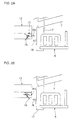
- Fig. 9A shows an example of a conventional sheet discharging apparatus.
- the conventional sheet discharging apparatus includes a large capacity tray, and a tray group including a number of stages of trays for sorting.
- a conveyor 2 is provided at a central portion in height direction on one side of an approximately rectangular body 1 of the apparatus.
- a container 3 for receiving the discharged sheet is provided on a side of body 1 opposing to conveyor 2.
- the image forming apparatus (not shown) is arranged on the side of conveyor 2.
- Conveyor 2 receives a sheet on which an image is formed by the image forming apparatus, conveys the sheet over a conveying surface 4 and discharges the sheet to container 3.
- the sheet conveying force is applied, in a copying machine, for example, by pinching the sheet from above and below by a pair of upper and lower discharge rollers provided near a discharge outlet and by rotating the rollers, so that the sheet is conveyed forward in the conveying direction.
- a vacuum conveyor suction belt
- Fig. 9B is a front view of conveyor 2 viewed from the direction of the arrow IX B in Fig. 9A.
- a pair of wings 5 are provided at opposing edges near a discharging outlet of conveyor 2.
- Wings 5 are reciprocal between a first position where each wing protrudes upward from conveying surface 4 as represented by the solid line in Fig. 9B, and a second position where each wing is positioned below conveying surface 4 as represented by two-dotted chain in Fig. 9B.
- wings 5 are arranged parallel to each other along the conveying direction, and adapted to be movable between the two positions mentioned above with opposing edges of the wings serving as rotation axes 5a for forward/rearward rotation.
- a solenoid 6 is provided as a driving source for the movement.
- Solenoid 6 is coupled near an outer side at a bottom surface of wing 5 (an edge opposing to the center of rotation), and solenoid 6 is conducted, so that the outer side of wing 5 is urged upward and rotated about rotation axis 5a to be placed at the first position. By stopping conduction to solenoid 6, wing 5 is rotated in the opposite direction and placed at the second position.
- an upper surface 5b of wing 5 When wing 5 is at the first position, an upper surface 5b of wing 5 provides an inclined surface which gradually rises in the outer and forward direction of conveying. When it is at the second position, the upper surface is horizontal and approximately flush with conveying surface 4. Upper surface 5b of wing 5 is adapted to be in contact with lower side surface of the sheet moving on conveying surface 4.
- Container 3 includes trays (bins) 7 allowing stacking of a small number of sheets arranged in multiple stages, and a large capacity tray 8 containing a large number of sheets.
- Trays 7 are provided inclined with the front side in sheet conveying direction raised upward, and the trays 7 are arranged aligned in vertical direction spaced by a prescribed distance from each other. Trays 7 can be elevated/lowered collectively by an elevating apparatus in body 1.
- Large capacity tray 8 is made relatively deep so as to increase capacity, and has sidewalls 8a on opposing edges and a stop wall 8b erected in front.
- the actual position of receiving the sheet is lower by a prescribed distance from the sheet discharging position. Therefore, the discharged sheet drops by this distance and stacked. Therefore, wings 5 are set at the first position so that the sheet is curved upward and discharged diagonally upward.
- the discharged sheet never has its forward portion bent and discharged downward, but the sheet flies over a relatively long distance in a straight extended state.
- the sheet abuts stop wall 8b and guided by sidewalls 8a, so that the number of sheets are successively stack in large capacity tray 8.
- Figs. 10A and 10B show another example of the conventional sheet discharging apparatus in which a large capacity tray 8' has a function of wings. More specifically, large capacity tray 8' has wings 5' attached integrally on the side of sheet discharging outlet. Similar to wings 5 set at the first position shown in Figs. 9A and 9B, each of the wings 5' provides an inclined surface gradually rising forward and outward along the conveying direction. When a sheet is conveyed, it is subjected to upward curving by upper ends of wings 5', and is contained in large capacity tray 8'. In such a structure, it is not necessary to elevate/lower wings 5' dependent on the tray used, so that the apparatus can be simplified and control is facilitated.
- the conventional sheet discharging apparatus described above suffers from the following problem.
- large capacity tray 8' When large capacity tray 8' is used, wings 5' are always used raised at the first position.
- the central portion of the sheet tends to rise.
- a vacuum conveyor is used as conveyor 2 and the rising force of the central portion of the sheet exceeds the vacuum attraction, the sheet would be away from the surface of the conveyor belt, and thus conveying force cannot be applied.
- unnatural force may be applied to the sheet, resulting in undesirable bending.
- large capacity tray 8' must be mounted protruding in the direction of sheet discharge by the thickness of wings 5' (thickness of the wings in the discharging direction), which results in increased size of the whole apparatus.
- EP-A-0 611 719 a paper ejection device is disclosed the technique of which is equivalent to the preamble of the independent claim 1.
- an object of the present invention is to provide a sheet discharging apparatus at a low cost.
- Another object of the present invention is to provide a sheet discharging apparatus which can be reduced in size.
- Another object of the present invention is to provide a sheet discharging apparatus allowing stacking and storage of sheets in accordance with quality of the sheets to be stored.
- a still further object of the present invention is to provide a sheet discharging apparatus in which wings can be moved upward/downward dependent on a tray to be used, by a simple mechanism and control.
- the sheet discharging apparatus includes switch means for not transmitting urging force by the urging member to said wings when the sheet is thick, and for transmitting the urging force by the urging member to the wings when the sheet is thin.
- Fig. 1A is a cross sectional side view showing a structure of the sheet discharging apparatus in accordance with a first embodiment of the present invention.
- Fig. 1B is a front view taken from the direction of the arrow 1B in Fig. 1A.
- Figs. 2A, 2B to 4A, 4B show details of edge portions of the wing in the conveying direction, illustrating function of the first embodiment.
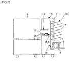
- Fig. 5 shows a structure of the sheet discharging apparatus in accordance with a second embodiment of the present invention.
- Figs. 6A, 6B, 7A and 7B illustrate function of the second embodiment of the present invention.
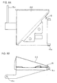
- Figs. 8A and 8B show an example of wing structure.
- Fig. 9A shows an exemplary structure of a conventional sheet stacking apparatus.
- Fig. 9B shows a structure for elevating/lowering wings of the conventional apparatus.
- Fig. 10A shows an exemplary structure of a conventional sheet discharging apparatus.
- Fig. 10B shows a large capacity tray of the conventional apparatus viewed from the direction of conveying the sheet.
- a sheet discharging apparatus 10 in accordance with the first embodiment of the present invention has a sheet sorter having a sorting function, provided integrally with an image forming apparatus 9, on the side of a sheet discharging outlet of image forming apparatus 9 such as a printer or a copying machine.
- Sheet discharging apparatus 10 includes an approximately rectangular body 11, a conveyor 12 provided at a central portion in height direction of body 11 on the side of image forming apparatus 9, and a container 13 provided at a side of body 11 opposing to conveyor 12.
- Conveyor 12 is not necessarily attached physically on body 11. For example, it may be attached to the side of image forming apparatus 9 with its tip end arranged to be inserted to the body 11.
- Conveyor 12 has a vacuum conveyor 14 at the central position in the height direction. Wings 15 which are movable upward/downward are provided in front of vacuum conveyor 14 in the conveying direction (at an end portion on the side of the container).
- Vacuum conveyor 14 includes a pair of conveyor belts 14a arranged on opposing sides of a conveying surface, and a fan 14b placed below and between the pair of conveyor belts 14a. By the operation of fan 14b, suction force is generated so that a sheet 20 to be discharged is sucked and attracted to be held on conveyor belts 14a.
- conveyor belts 14a are driven and rotated, the attracted sheet 20 is conveyed and discharged to container 13.
- a number of through holes are formed in the belt surfaces of conveyor belts 14a, so that air sucked by fan 14b is drawn inside through the through holes of conveyor belt 14a. This ensures attraction of sheet 20 onto conveyor belt 14a.
- Wings 15 are provided movable upward/downward along opposing edges of conveyor belts 14a as in the prior art (see Fig. 1B). Each wing 15 has an approximately triangular vertical cross section orthogonal to the sheet conveying direction. Vertexes of the triangles are positioned on opposing sides of wings 15. The wing also has an approximately triangular vertical cross section parallel to the sheet conveying direction, with the vertexes of the triangles positioned behind the feeding direction (see Fig. 1A). In other words, wing 15 has such a shape that is thicker outward and forward along the feeding direction.
- Edge portions of opposing sides of wings 15 serve as rotation axes 15a, and each wing rotates forward/rearward in a prescribed angular range.
- wing is reciprocal between a first position where an upper surface 15b of the wing protrudes upward from conveyor belt 14a and a second position where upper surface 15b of wing 15 is positioned lower than conveyor belt 14a.
- Fig. 1A shows the second position while Fig. 1B shows the first position. Because of gravity and balance of wings 15, each wing is set such that it rotates with the outer side moving downward to be at the second position by the weight of itself, unless an external force is applied.
- a projection 15c having a thin bar-like shape is provided to protrude at a lower portion in front of wing 15 in the sheet conveying direction.
- the projection 15c has a tip end formed to be protruded outward than the front surface of a box body 12a of conveyor 12 in the conveying direction.
- wing 15 is mostly contained in box 12a.
- box 12a is open up from the conveying surface 14a of conveyor belt in front of the sheet conveying direction, allowing discharge of the sheet.
- two guide holes 12b, 12b curved arcuate are provided at a prescribed position of a front surface lower than the conveying surface.
- Tip ends of projections 15c attached to wings 15, 15 are protruded outward through guide holes 12b and 12b.
- radius of curvature of guide hole 12b is made approximately conforming to moving track of projection 15c accompanying forward/rearward rotation of wing 15. Accordingly, projection 15c moves guided by guide hole 12b.
- movable range of projection 15c and hence of wing 15 is regulated by guide hole 12b.
- wing 15 when projection 15c is positioned at an upper edge of guide hole 12b as shown in Fig. 1B, wing 15 is at the highest first position, and when projection 15c is positioned at a lower edge of guide hole 12b, wing 15 is at the lowest second position.
- projection 15c is attached movable in a thrust direction at a lower end of wing 15.
- An operation lever 16 is connected to a proximal end (rearward in the conveying direction) of projection 15c, and by rotating operation lever 16 forward/rearward, the projection moves forward to assume a state protruding considerably from the front surface of box 12a, as shown in Fig. 2A, and moves backward to assume a state protruding only slightly from the front surface of box 12a, as shown in Fig. 2B.
- Operation lever 16 and projection 15c are in contact with each other and separable. More specifically, a convex portion is provided at a side surface of projection 15c, and operation lever 16 is brought into contact with the convex portion. Therefore, when projection 15c is urged upward by urging member 18 as will be described later, it is separated smooth from operation lever 16, allowing elevation of projection 15c.
- Container 13 includes, in this example, trays each for containing a small number of discharged sheets, and a large capacity tray 8 capable of containing a large number of sheets.
- a plurality of trays 7 are prepared arranged in multiple stages in vertical direction, so as to enable use as a sorter. It goes without saying that the trays may not be used as a sorter, and sheets may be discharged to a prescribed one of the trays 7.
- Trays 7 and large capacity tray 8 are mounted on a frame 17, and movable upward/downward collectively. Specific structures of trays 7 and large capacity tray 8 are the same as those of the prior art. Therefore, detailed description thereof is not repeated.
- the plurality of trays 7 and large capacity tray 8 are moved upward/downward collectively on frame 17.
- the trays 7 and large capacity tray 8 By moving upward/downward the trays 7 and large capacity tray 8 to position a prescribed tray 7 or the large capacity tray 8 aligned with the sheet discharging surface of conveyor 12, the discharged sheet is received and stacked.
- urging member 18 is mounted at a prescribed position on a side surface of frame 17 on the side of conveyor 12.
- Urging member 18 has an approximately L shape, with one side approximately orthogonal to the direction of movement of container 13 and protruding to the side of conveyor 12. This one side is longer than the distance between the tip end of projection 15c largely protruding forward and frame 17, and shorter than the distance between the tip end of projection 15c moved rearward and the frame 17. More specifically, when projection 15c moves forward, urging member 18 is brought into contact with projection 15c, and when projection 15c moves rearward, urging member 18 goes out of contact with projection 15c.
- urging member 18 is fixed on frame 17 with its tip end facing downward. Accordingly, urging member 18 is in contact with projection 15c and reaction force generated when pressing down acts in the direction of pressing urging member 18 toward frame 17. Accordingly, frame 17 and urging member 18 can be firmly joined.
- Position of attaching urging member 18 is approximately the same as the height position of large capacity tray 8, so that the tray and urging member satisfy relative positional relation such that when large capacity tray 8 is placed at the sheet discharging position, urging member 18 is brought into contact with and presses projection 15c upward.
- urging member 18 is formed by a plate spring.
- urging member 18 is separate from projection 15c. Since there is not an upward force acting on projection 15c formed integrally with wing 15, wing 15 lowers by the weight of itself, projection 15c is supported by the lower edge of guide hole 12b, preventing further lowering, and hence wing 15 is stationary and rest on the second position shown in the figure. Accordingly, upper surface 15b of wing 15 is positioned flush with or lower than conveyor belt 14a. Accordingly, the sheet conveyed over conveyor belt 14a is discharged extending straight and flat, and stacked on a prescribed tray 7.
- frame 17 is elevated. Accordingly, large capacity tray 8 is elevated, together with urging member 18. An upper surface of one side of urging member 18 protruding in the direction of conveyor 12 abuts the lower surface of projection 15c.
- upward urging force pressing force
- projection 15c moves to go upward. More specifically, upward force is applied through projection 15c to the tip end in the sheet conveying direction of wing 15 which is formed integrally with projection 15c. Since wing 15 is maintained at the second position simply by the weight of itself, wing 15 is rotated about rotation axis 15a by the urging force, so that outer side is elevated.
- wing 15 is placed at the first position, with upper surface 15b of wing 15 protruding upward from conveyor belt 14a and providing an inclined surface crossing at a prescribed angle with conveyor belt 14a (see Figs. 1B and 3A).
- sheet 20 conveyed over conveyor belts 14a have opposing edges 20a in contact with upper surfaces 15b of wings 15 and curved upward, whereby stiffness is increased (see Fig. 1B).
- the angle formed by upper surfaces 15a of wings 15 at the first position and conveyor belts 14a is selected to be appropriate for the upward curving of sheet 20. Therefore, discharged sheet 20 does not immediately fall but stacked in large capacity tray 8 in a stable manner.
- the sheet after discharge does not have the front portion hanging downward, and the sheet flies relatively far in a straight extended state. Therefore, when the large capacity tray is to be used, wings are protruded so that sheets are discharged relatively far in a straight extended state, so that sheets can be stacked on the large capacity tray positioned lower by a prescribed distance from the discharging portion, not bent while the sheets drop.
- the sheet is discharged to the tray positioned near the discharging portion without upward curving.
- urging member 18 is formed of a plate spring. Therefore, even when urging member 18 rises slightly upper than the first position, the plate spring elastically deforms, so that excessive force is not applied to projection 15c (wing 15) while elevation of frame 17 (large capacity tray 8) is allowed.
- operation lever 16 is rotated to move projection 15c rearward.
- large capacity tray 8 is elevated in the similar manner as described above, so that urging member 18 is elevated.
- urging member 18 is not in contact with projection 15c, and therefore upward urging force does not act on projection 15c.
- urging member 18 is positioned upper than projection 15c as shown in Fig. 3B, and hence projection 15c and wing 15 are not raised. Accordingly, wing 15 does not protrude upward from the belt surface of conveyor belt 14a as shown in Fig. 4B.
- sheet 20 is kept flat, and by the suction force generated by fan 14b, sheet 20 is attracted and held on conveyor belt 14a, and a prescribed conveying force is applied. Though upward curving by raising opposing edges of sheet 20 is not performed, such sheet has sufficient sturdiness to be discharged in flat extended state, and therefore the sheet is dropped and supplied to large capacity tray 8.
- Determination as to whether wings 15 are to be used or not is made such that wings are not used when the sheet is thick and wings are used when the sheet is thin. More specifically, when the sheet is strong enough to be stacked on tray 8 in the extended straight state without upward curving, wings may not be used. Even in that case, wings may be used if the center of the sheet is sucked and attracted to be held on conveyor belts 14a with both edges raised by the wing, dependent on correlation between the sturdiness of the sheet and the attraction force of fan 14b.
- operation lever 16 Since it is possible to determine whether wings 15 are to be used or not, under a certain condition, operation lever 16 is operated so that urging force of urging member is not transmitted to wings 15 even when the large capacity tray is positioned at the discharging portion, and hence wings 15 are not raised. Even when the large capacity tray is used, upward curving may be prevented depending on condition, so that more flexible setting and operation mode in accordance with specific condition is possible, whereby sheets can be surely discharged and stacked on the tray.
- switching may be done automatically.
- Fig. 5 shows a second embodiment of the sheet discharging apparatus in accordance with the present invention.
- urging member 18 is rotatable in forward/rearward directions about an axis 18a provided on frame 17, and urging member 18 assumes two positions, that is, a state where it abuts projection 15c of wing 15 shown in Figs. 6A and 6B, and a state, rotated clockwise from the first state, where one side of urging member 18 is not in contact with projection 15c as shown in Figs. 7A and 7B.
- it is not necessary to move projection 15c in the thrust direction as in the first embodiment. Therefore, it can be formed integrally with the body of wing 15. Even when it is formed by a separate member, it is fixed at a prescribed position on the front surface of wing 15.
- urging member 18 is set to such an attitude as shown in Fig. 6A. Then, urging member 18 which is elevated together with large capacity tray 8 comes into contact with projection 15c, and presses the projection upward.
- large capacity tray 8 reaches the discharging portion (the position of use) as shown in Fig. 6B, wings 15 are also elevated to the prescribed position. Accordingly, opposing edges of the sheet are raised and the sheet is discharged curved upward.
- urging member 18 When a thick and sturdy sheet is printed and discharged, urging member 18 is set to such a position as shown in Fig. 7A. Then the urging member is not brought into contact with projection 15c even when large capacity tray 8 is elevated, and wings 15 are not elevated even when large capacity tray 8 is placed to the discharging position (position of use) as shown in Fig. 7B. Therefore, the sheet is discharged in the flat extended state.
- Other structures, functions and effects are the same as the first embodiment. Therefore, description thereof is not repeated.
- wings 15 used in both embodiments described above are integrally formed to a prescribed shape by resin molding.
- the wing has complicated shape as it has a mechanism for elevation/lowering (rotation), and it must be positioned in a desired attitude at a prescribed position in conveyor 12 at the time of elevation and lowering, and hence it is difficult to form the wings by plate metal.
- Conventional wings of the type which moves upward/downward are formed of synthetic resin from the reason described above.
- the resin has high friction coefficient, which presents resistance in conveying when the sheet is discharged, hindering smooth feeding. Further, as the sheet moves with friction, static electricity is generated, enlarging load on the sheet which is being conveyed. This results in dropping midway or failure of feeding in the conveyor 12 as the speed of discharge decreases, possibly causing jam and failure of discharge.
- body of wing 15 is manufactured integrally by synthetic resin as in the prior art, and at least the conveying surface (upper surface) which is in contact with the sheet is covered by a metal plate 22. This decreases friction resistance and suppresses static electricity, enabling smooth conveying and discharging process.
- center of rotation 15a is provided on opposing side of wings 15, it is not limited thereto.
- rotation axis may be provided behind in the sheet conveying direction for allowing forward/rearward rotation about an axis orthogonally intersecting the conveying direction with the front side of the wing protruded/recessed with respect to the conveyor belt.
- the wings are returned to the second position by natural fall utilizing the weight of wings themselves in the above described embodiments, the wings may be returned to the second position by utilizing elastic force (elastic recovering force) of an elastic member such as spring or rubber.
- the present invention is applied to an apparatus having a plurality of trays 7 for small number of sheets for sorting function
- application of the present invention is not limited thereto.
- the present invention may be applied to a sheet discharging apparatus having one tray 7 and one large capacity tray 8.
- the structure in which the urging member is provided near the large capacity tray and the wings are eventually elevated by the urging member as in the above described embodiments may be applied as it is.
- the present invention may be applied as a reverse structure. More specifically, though not shown, the urging member may be provided near the tray for small number of sheets, and the wings may be set at the protruding first position when there is not an urging force. In order to maintain the first position, elastic force by an elastic member, for example, may be utilized.
- the tray for stacking "small number of” sheets and the large capacity tray stacking "a large number of” sheets are only relative terms specifying the types of the trays.
- the large capacity tray refers to that tray for which upward curving to increase stiffness by the wings is required
- the tray for the small number of sheets refers to one that does not require upward curving, regardless of the types of sheets.
- the state of wings at a position "lower than the conveying surface” covers both the position which is flush with the conveying surface and the position further below, as illustrated in the embodiments. Further, this position also covers a position slightly upper than the conveying surface not higher enough to perform upward curving.
Landscapes
- Engineering & Computer Science (AREA)
- Mechanical Engineering (AREA)
- Pile Receivers (AREA)
- Collation Of Sheets And Webs (AREA)
Claims (6)
- Blattausgabevorrichtung (10) mit einer Blattausgabeeinheit (12), umfassend:dadurch gekennzeichnet, daß sich das Schubelement (18) mit dem Behälterablagekasten (7) nach oben/unten bewegt.einen Behälterablagekasten (7), der zum Aufnehmen und Stapeln eines ausgegebenen Blatts nach oben/unten beweglich ist, wenn er nahe der Ausgabeeinheit (12) angeordnet ist;Flügel (15), die an der Ausgabeeinheit (12) vorgesehen sind, zum Anheben von entgegengesetzten Kanten des auszugebenden Blatts (20) ;wobei die Flügel (15) durch ein Schubelement (18) geschoben werden, welches die Flügel schiebt, wenn die entgegengesetzten Kanten des auszugebenden Blatts (20) nach oben angehoben werden sollten;
- Blattausgabevorrichtung nach Anspruch 1, welche ferner umfaßt:
ein Schaltmittel (16, 18a) zum Schalten der Übertragung/Nicht-Übertragung der Schubkraft von dem Schubelement (18) auf die Flügel (15), was die Auswahl hinsichtlich dessen, ob die Flügel (15) angehoben werden sollen oder nicht, durch das Schaltmittel (16, 18a) ermöglicht. - Blattausgabevorrichtung nach Anspruch 1, wobei mindestens eine mit dem Blatt (20) in Kontakt stehende Oberfläche der Flügel (15) mit einer Metallabdeckung bedeckt ist.
- Blattausgabevorrichtung nach Anspruch 1, welche ferner ein Schaltmittel (16, 18a), um die Schubkraft durch das Schubelement (18) auf die Flügel (15) nicht zu übertragen, wenn das Blatt (20) dick ist, und um die Schubkraft durch das Schubelement (18) auf die Flügel (15) zu übertragen, wenn das Blatt (20) dünn ist, umfaßt.
- Blattausgabevorrichtung nach Anspruch 4, wobei
der Behälterablagekasten (7, 8) eine Vielzahl von Behälterablagekästen umfaßt, die in vertikaler Richtung vorgesehen sind, wobei das Schubelement (18) an einem untersten der Vielzahl von Ablagekästen befestigt ist. - Blattausgabevorrichtung nach Anspruch 5, wobei
der unterste Behälterablagekasten (8) ein größeres Fassungsvermögen aufweist als die übrigen (7) der Vielzahl von Ablagekästen.
Applications Claiming Priority (3)
| Application Number | Priority Date | Filing Date | Title |
|---|---|---|---|
| JP11501897A JP3548781B2 (ja) | 1997-04-18 | 1997-04-18 | シート排出装置 |
| JP115018/97 | 1997-04-18 | ||
| JP11501897 | 1997-04-18 |
Publications (3)
| Publication Number | Publication Date |
|---|---|
| EP0872442A2 EP0872442A2 (de) | 1998-10-21 |
| EP0872442A3 EP0872442A3 (de) | 1999-08-11 |
| EP0872442B1 true EP0872442B1 (de) | 2001-09-12 |
Family
ID=14652217
Family Applications (1)
| Application Number | Title | Priority Date | Filing Date |
|---|---|---|---|
| EP98107019A Expired - Lifetime EP0872442B1 (de) | 1997-04-18 | 1998-04-17 | Apparat zum Ausgeben von Blättern mit mechanisch kontrollierten Flügeln |
Country Status (5)
| Country | Link |
|---|---|
| US (1) | US5975521A (de) |
| EP (1) | EP0872442B1 (de) |
| JP (1) | JP3548781B2 (de) |
| CN (1) | CN1078171C (de) |
| DE (1) | DE69801610T2 (de) |
Families Citing this family (18)
| Publication number | Priority date | Publication date | Assignee | Title |
|---|---|---|---|---|
| JP3537326B2 (ja) * | 1998-10-26 | 2004-06-14 | 理想科学工業株式会社 | 画像形成装置 |
| US6231043B1 (en) * | 1999-07-29 | 2001-05-15 | Lexmark International, Inc. | Retractable exit tray for imaging apparatus |
| JP2001233527A (ja) * | 2000-02-22 | 2001-08-28 | Riso Kagaku Corp | 排紙装置及び印刷装置 |
| DE10023796A1 (de) * | 2000-05-15 | 2001-11-22 | Nexpress Solutions Llc | Ablagetisch |
| JP3962605B2 (ja) | 2002-02-28 | 2007-08-22 | キヤノン株式会社 | シート処理装置及び画像形成装置 |
| US6942211B2 (en) * | 2003-07-11 | 2005-09-13 | Hewlett-Packard Development Company, Lp | Mobile printer and paper feeder |
| US7434802B2 (en) * | 2004-02-27 | 2008-10-14 | Canon Kabushiki Kaisha | Sheet discharging apparatus and sheet treating apparatus provided with the same |
| US7597319B2 (en) * | 2005-05-20 | 2009-10-06 | Hewlett-Packard Development Company, L.P. | Sheet handling using a ramp and grippers on an endless belt |
| US7246962B2 (en) * | 2005-07-29 | 2007-07-24 | Lexmark International, Inc. | Exit roller system for an imaging apparatus |
| US7494121B2 (en) * | 2006-03-07 | 2009-02-24 | Xerox Corporation | Automatically variably shaped sheet stacking tray surface for printed sheets |
| JP4764840B2 (ja) * | 2007-02-08 | 2011-09-07 | 理想科学工業株式会社 | 排紙装置 |
| JP4954119B2 (ja) * | 2008-02-26 | 2012-06-13 | デュプロ精工株式会社 | 排紙装置 |
| US9656484B2 (en) * | 2013-07-29 | 2017-05-23 | Hewlett-Packard Development Company, L.P. | Media output guide assembly |
| EP3274282B1 (de) * | 2015-03-25 | 2021-07-14 | Canon Production Printing Netherlands B.V. | Bogenförderer zum fördern einer bahn, verfahren zum transport eines blattes in einem bogenförderer, tintenstrahldruckvorrichtung mit dem bogenförderer |
| JP6365412B2 (ja) * | 2015-05-26 | 2018-08-01 | 京セラドキュメントソリューションズ株式会社 | 画像形成装置 |
| WO2017099739A1 (en) | 2015-12-09 | 2017-06-15 | Hewlett-Packard Development Company, L.P. | Media tray with ramp |
| CN105883466A (zh) * | 2016-06-01 | 2016-08-24 | 严涛涛 | 一种打印机用的纸张托盘装置及其使用方法 |
| CN106044338A (zh) * | 2016-06-01 | 2016-10-26 | 王启先 | 一种可分拣的打印机后纸张托盘装置及其使用方法 |
Family Cites Families (7)
| Publication number | Priority date | Publication date | Assignee | Title |
|---|---|---|---|---|
| US2381430A (en) * | 1943-07-02 | 1945-08-07 | Christensen Machine Co | Sheet delivery mechanism |
| JPS5315362Y2 (de) * | 1973-10-03 | 1978-04-22 | ||
| US4354408A (en) * | 1980-09-12 | 1982-10-19 | Valcour Imprinted Papers, Inc. | Place mat producing and dispensing apparatus |
| US5407192A (en) * | 1992-05-19 | 1995-04-18 | Riso Kagaku Corporation | Sorter having a pivoting non-sort bin |
| JP3213424B2 (ja) * | 1993-02-15 | 2001-10-02 | 理想科学工業株式会社 | 孔版印刷装置の排紙装置 |
| JPH0967069A (ja) * | 1995-09-01 | 1997-03-11 | Sharp Corp | エアーを利用するシート給紙装置 |
| JP3635477B2 (ja) * | 1996-10-03 | 2005-04-06 | オムロン株式会社 | シート積載装置 |
-
1997
- 1997-04-18 JP JP11501897A patent/JP3548781B2/ja not_active Expired - Lifetime
-
1998
- 1998-04-17 DE DE69801610T patent/DE69801610T2/de not_active Expired - Fee Related
- 1998-04-17 CN CN98106660A patent/CN1078171C/zh not_active Expired - Fee Related
- 1998-04-17 US US09/062,536 patent/US5975521A/en not_active Expired - Fee Related
- 1998-04-17 EP EP98107019A patent/EP0872442B1/de not_active Expired - Lifetime
Also Published As
| Publication number | Publication date |
|---|---|
| JP3548781B2 (ja) | 2004-07-28 |
| EP0872442A2 (de) | 1998-10-21 |
| CN1197758A (zh) | 1998-11-04 |
| US5975521A (en) | 1999-11-02 |
| JPH10291725A (ja) | 1998-11-04 |
| EP0872442A3 (de) | 1999-08-11 |
| DE69801610T2 (de) | 2002-07-04 |
| DE69801610D1 (de) | 2001-10-18 |
| CN1078171C (zh) | 2002-01-23 |
Similar Documents
| Publication | Publication Date | Title |
|---|---|---|
| EP0872442B1 (de) | Apparat zum Ausgeben von Blättern mit mechanisch kontrollierten Flügeln | |
| US5884910A (en) | Evenly retractable and self-leveling nips sheets ejection system | |
| US5026034A (en) | Document output apparatus having anti-dishevelment device | |
| EP0640546B1 (de) | System zum Stapeln von Blättern mit grossem Aufnahmevermögen und mit einer in der Höhe variierbaren Eingabe und Stapelausrichtung | |
| US10494207B2 (en) | Sheet feeding device and image forming system | |
| EP0875474B2 (de) | Reibungsunterlage für Vereinzelung von Bögen | |
| JP3363685B2 (ja) | シート材給送装置及び記録装置 | |
| JP2001063847A (ja) | 給紙装置 | |
| US6688590B2 (en) | Dual tray printer with single drive shaft and dual media picks | |
| JPH072536B2 (ja) | 底部シート分離・給送装置 | |
| JPH057291B2 (de) | ||
| CA1217518A (en) | Enhanced envelope feeding | |
| US5415388A (en) | Sheet feeding apparatus | |
| EP0590825A1 (de) | Papierstapelsystem für Druckeinrichtungen | |
| US6296244B1 (en) | Method and apparatus for guiding media | |
| JPH01275369A (ja) | 紙などのシート用分類装置 | |
| JP3635477B2 (ja) | シート積載装置 | |
| JPH1053340A (ja) | 給紙カセット | |
| JPH085980Y2 (ja) | ソータ | |
| JPH0752118Y2 (ja) | 給紙装置 | |
| KR20050077360A (ko) | 2 가지 방식의 용지 픽업 시스템 | |
| JPH08187443A (ja) | シュレッダの給紙装置 | |
| KR940002122B1 (ko) | 복사지 분류장치 | |
| MXPA98003435A (en) | Friction pad for ho separator | |
| JPS58130835A (ja) | 給紙装置 |
Legal Events
| Date | Code | Title | Description |
|---|---|---|---|
| PUAI | Public reference made under article 153(3) epc to a published international application that has entered the european phase |
Free format text: ORIGINAL CODE: 0009012 |
|
| AK | Designated contracting states |
Kind code of ref document: A2 Designated state(s): DE FR GB |
|
| AX | Request for extension of the european patent |
Free format text: AL;LT;LV;MK;RO;SI |
|
| PUAL | Search report despatched |
Free format text: ORIGINAL CODE: 0009013 |
|
| AK | Designated contracting states |
Kind code of ref document: A3 Designated state(s): AT BE CH CY DE DK ES FI FR GB GR IE IT LI LU MC NL PT SE |
|
| AX | Request for extension of the european patent |
Free format text: AL;LT;LV;MK;RO;SI |
|
| 17P | Request for examination filed |
Effective date: 20000121 |
|
| AKX | Designation fees paid |
Free format text: DE FR GB |
|
| 17Q | First examination report despatched |
Effective date: 20000406 |
|
| GRAG | Despatch of communication of intention to grant |
Free format text: ORIGINAL CODE: EPIDOS AGRA |
|
| GRAG | Despatch of communication of intention to grant |
Free format text: ORIGINAL CODE: EPIDOS AGRA |
|
| GRAH | Despatch of communication of intention to grant a patent |
Free format text: ORIGINAL CODE: EPIDOS IGRA |
|
| GRAH | Despatch of communication of intention to grant a patent |
Free format text: ORIGINAL CODE: EPIDOS IGRA |
|
| GRAA | (expected) grant |
Free format text: ORIGINAL CODE: 0009210 |
|
| AK | Designated contracting states |
Kind code of ref document: B1 Designated state(s): DE FR GB |
|
| REF | Corresponds to: |
Ref document number: 69801610 Country of ref document: DE Date of ref document: 20011018 |
|
| REG | Reference to a national code |
Ref country code: GB Ref legal event code: IF02 |
|
| ET | Fr: translation filed | ||
| PLBE | No opposition filed within time limit |
Free format text: ORIGINAL CODE: 0009261 |
|
| STAA | Information on the status of an ep patent application or granted ep patent |
Free format text: STATUS: NO OPPOSITION FILED WITHIN TIME LIMIT |
|
| 26N | No opposition filed | ||
| PGFP | Annual fee paid to national office [announced via postgrant information from national office to epo] |
Ref country code: FR Payment date: 20060419 Year of fee payment: 9 |
|
| PGFP | Annual fee paid to national office [announced via postgrant information from national office to epo] |
Ref country code: GB Payment date: 20060421 Year of fee payment: 9 |
|
| PGFP | Annual fee paid to national office [announced via postgrant information from national office to epo] |
Ref country code: DE Payment date: 20060502 Year of fee payment: 9 |
|
| GBPC | Gb: european patent ceased through non-payment of renewal fee |
Effective date: 20070417 |
|
| PG25 | Lapsed in a contracting state [announced via postgrant information from national office to epo] |
Ref country code: DE Free format text: LAPSE BECAUSE OF NON-PAYMENT OF DUE FEES Effective date: 20071101 |
|
| PG25 | Lapsed in a contracting state [announced via postgrant information from national office to epo] |
Ref country code: GB Free format text: LAPSE BECAUSE OF NON-PAYMENT OF DUE FEES Effective date: 20070417 |
|
| PG25 | Lapsed in a contracting state [announced via postgrant information from national office to epo] |
Ref country code: FR Free format text: LAPSE BECAUSE OF NON-PAYMENT OF DUE FEES Effective date: 20070430 |