EP0874723B1 - Spritzgussvorrichtung - Google Patents
Spritzgussvorrichtung Download PDFInfo
- Publication number
- EP0874723B1 EP0874723B1 EP97900602A EP97900602A EP0874723B1 EP 0874723 B1 EP0874723 B1 EP 0874723B1 EP 97900602 A EP97900602 A EP 97900602A EP 97900602 A EP97900602 A EP 97900602A EP 0874723 B1 EP0874723 B1 EP 0874723B1
- Authority
- EP
- European Patent Office
- Prior art keywords
- injection
- moulding device
- discharge opening
- insert
- mouth
- Prior art date
- Legal status (The legal status is an assumption and is not a legal conclusion. Google has not performed a legal analysis and makes no representation as to the accuracy of the status listed.)
- Expired - Lifetime
Links
Images


Classifications
-
- B—PERFORMING OPERATIONS; TRANSPORTING
- B29—WORKING OF PLASTICS; WORKING OF SUBSTANCES IN A PLASTIC STATE IN GENERAL
- B29C—SHAPING OR JOINING OF PLASTICS; SHAPING OF MATERIAL IN A PLASTIC STATE, NOT OTHERWISE PROVIDED FOR; AFTER-TREATMENT OF THE SHAPED PRODUCTS, e.g. REPAIRING
- B29C45/00—Injection moulding, i.e. forcing the required volume of moulding material through a nozzle into a closed mould; Apparatus therefor
- B29C45/17—Component parts, details or accessories; Auxiliary operations
- B29C45/46—Means for plasticising or homogenising the moulding material or forcing it into the mould
- B29C45/58—Details
- B29C45/586—Injection or transfer plungers
-
- B—PERFORMING OPERATIONS; TRANSPORTING
- B29—WORKING OF PLASTICS; WORKING OF SUBSTANCES IN A PLASTIC STATE IN GENERAL
- B29C—SHAPING OR JOINING OF PLASTICS; SHAPING OF MATERIAL IN A PLASTIC STATE, NOT OTHERWISE PROVIDED FOR; AFTER-TREATMENT OF THE SHAPED PRODUCTS, e.g. REPAIRING
- B29C45/00—Injection moulding, i.e. forcing the required volume of moulding material through a nozzle into a closed mould; Apparatus therefor
- B29C45/17—Component parts, details or accessories; Auxiliary operations
- B29C45/46—Means for plasticising or homogenising the moulding material or forcing it into the mould
- B29C45/53—Means for plasticising or homogenising the moulding material or forcing it into the mould using injection ram or piston
- B29C45/532—Means for plasticising or homogenising the moulding material or forcing it into the mould using injection ram or piston using a hollow injection ram co-operating with a coaxial screw
Definitions
- the invention relates in particular to an injection molding device for rubber, rubber or similar materials, such as Elastomers, thermosets and cross-linkable polymers.
- EP 0 287 001 A1 relates to a device for injection molding of materials with a plasticizing unit that has an extruder outlet, and with an injection unit, the a plunger and a spray channel with a discharge opening having.
- a plasticizing unit that has an extruder outlet, and with an injection unit, the a plunger and a spray channel with a discharge opening having.
- the extruder outlet of the plasticizing unit with the discharge opening connected to the plunger.
- the extruder outlet is separated from the discharge opening and the spray channel is connected to a molding tool.
- DE 91 10 240 U1 describes an injection molding device, in which a plasticizing unit is fixed with a plunger is connected through which in the injection cylinder leading filling channel runs. The one pointing away from the injection cylinder End is with an extruder exit of the plasticizing unit connected. The mouth of the filling channel is located themselves at the top of the cone-shaped free End of the plunger.
- the bottom surface of the injection cylinder is made up of an insert and is corresponding to the Shape of the free end of the plunger conical, where a discharge opening in use with the mouth of the filling channel is aligned in the plunger.
- the plunger move accordingly becomes.
- the locking slide is then withdrawn and the injection unit is coupled to a molding tool.
- the spray piston is inserted into the injection cylinder, the check valve in the filling channel in the closed Position is pressed and the material from the Injection cylinder is pressed into the mold cavity of the tool.
- the syringe plunger is fully inserted into the injection cylinder is the mouth of the filling channel with the discharge opening in connection. After a certain time the Injection unit separated from the mold, the vulcanized part pulled out of the spray channel becomes.
- DE-A-4304489 describes an injection molding machine, the one Injection cylinder and an injection piston which can be moved therein having.
- the injection cylinder is over one in the injection piston arranged filling channel fillable and via a discharge opening in the Spray cylinder can be emptied.
- the invention has for its object an injection molding device to provide, which is easy to use. This object is achieved with the features of the claims.
- An injection molding device has in particular an injection unit that has an injection cylinder and comprises a spray plunger movable therein.
- the The injection cylinder is arranged in the injection plunger Filling channel can be filled with at least one mouth. Over a The discharge opening in the injection cylinder can be emptied.
- the The mouth of the filling channel is spatial from the discharge opening and thermally separated.
- the discharge opening is thus free of residues. It will in particular certainly avoided that partially vulcanized Material residues in the mold during the next injection process be filled in.
- the injection molding device according to the invention thus allows easier handling.
- the injection plunger and the injection cylinder preferably each have at least one sealing surface in the retracted Position of the plunger in engagement with each other come. This has the advantage that by retracting the Injection plunger to seal the mouth of the filling channel Dispensing opening in the injection cylinder is reached. To this This ensures that the in the filling channel up to Material reaching the mouth of the material filled into the mold Material is safely separated. Furthermore, with the next filling the injection cylinder a precisely dosed Amount of material provided.
- the temperature depends on the material to be processed preferably controlled in the area of the filling channel, that vulcanization of the material present in the filling channel is safely avoided.
- the injection molding device When the injection molding device is coupled with an injection tool it comes in the area the respective contact points between the mold and the injection cylinder and the injection cylinder and the Spray pistons for heat transfer.
- the temperatures preferably controlled so that the mold a temperature of about 180 ° C, the injection cylinder a temperature of approximately 120 ° C. in the area of the discharge opening and the plunger has a temperature in the area of the filling channel of about 80 ° C.
- the temperature is controlled by appropriate heating or cooling taking into account the heat transfer resistance and the thermal conductivity of the individual components.
- the injection cylinder has a complementary shape. there the front tip of the plunger protrudes at least partially into the dispensing opening. This will be more advantageous Way achieved that when retracting the plunger the filling in the injection cylinder is complete is dispensed through the dispensing opening and is particularly preferred the material in the delivery opening is at least partially is expelled.
- free end of the plunger conical and the Bottom surface of the injection cylinder has a complementary cone shape on, with the discharge opening in the area of the tip is arranged. At the same time is the mouth of the filling channel arranged in the lateral surface of the conical end.
- A is preferably at the free end of the injection plunger Insert arranged. This bet forms at least one Part of the tapered free end of the plunger.
- the insert is made of a different material than the plunger can be manufactured. Furthermore can the insert is manufactured and processed separately. Preferably is the insert made of a heat-insulating material manufactured.
- the injection cylinder more preferably has in the bottom area a mouthpiece insert with the dispensing opening on, which is preferably heat-insulating.
- Material for the mouthpiece insert is preferably a Chrome-nickel steel such as V2A, V4A or ceramic made of sintered materials used. This has the advantage that with a coupling the injection unit with the mold, the heat conduction from the discharge opening to the filling channel and in particular whose mouth is interrupted or at least reduced.
- an extruder screw is preferably arranged in the axial direction. It is further preferred between the extruder screw and the filling channel a check valve is arranged, which preferably automatically closes when the pressure in the injection cylinder is larger than in the area of the extruder screw.
- the check valve is advantageously between the rear end of the insert and the free end of the extruder screw arranged.
- This arrangement has the advantage that the filling channel in the plunger has a short length and corresponds essentially to the length of the insert and that the check valve by simply removing the insert is accessible.
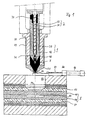
- an injection molding device has an injection unit 1, which essentially consists of an injection cylinder 20 and an injection piston movable therein 10 exists.
- an insert 16 arranged at the free end of the plunger 10 .
- the free end along with that The insert is conical.
- a Filling channel 12 with a branch from one entrance to three Outputs trained.
- the mouths 14 of the three exits are spaced from the tip and are 120 ° apart from each other along the circumference of the outer surface of the insert distributed.
- the injection cylinder 20 is essentially a hollow cylinder formed, a mouthpiece 25 is arranged at its free end is.
- a mouthpiece insert 26 is arranged on the mouthpiece 25, and both have towards the cylinder interior a conical surface that is complementary to the conical Tip of the plunger is.
- a spray channel 22 is formed with a discharge opening 24.
- the mouthpiece insert 26 is in its upper part Mouthpiece 25 preferably inserted by screws. Here there is a good heat-conducting connection to the mouthpiece 25.
- the mouthpiece 25 is through bath fluid in the channel system 39 depending on the setting, in the temperature range of 70 ° kept up to 80 ° C.
- the lower area of the mouthpiece insert 26 protrudes freely from the mouthpiece 25. In the area of freely protruding part of the mouthpiece insert shows the Spray channel 22 a flared outwards Diffuser section on.
- the hollow cylinder and the mouthpiece are formed in one piece. Otherwise, the structure is the same as that described above Arrangement.
- the injection piston 10 is within the injection cylinder 20 a drive (not shown) between a retracted Position and a retracted position in the conical end of the plunger with the conical Surface in the mouthpiece or mouthpiece insert in contact comes, movable.
- a plasticizing unit 3 is arranged in the injection plunger 10.
- the plasticizing unit 3 consists essentially from a hollow cylinder provided axially in the injection piston 10 32 and an extruder screw 30 arranged therein. In the area the rear end of the extruder screw there is an extruder inlet 34 and in the area of the free end an extruder outlet 36.
- the extruder screw is operated by one Drive (not shown) driven.
- a check valve 40 is provided between the extruder outlet 36 and the rear end of the insert 16.
- the check valve consists of a Ball that closes the extruder outlet as soon as the pressure in the injection cylinder exceeds the pressure in the extruder. In the passage in the other direction is free.
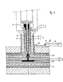
- a mold 5 consists of two parts that are assembled form a mold cavity 52.
- the mold nest 52 is over a Injection opening 54 can be filled.
- Injection opening 54 can be filled in the upper part of the mold.
- recess 56 into which the injection unit 1 can be retracted.
- the preferred embodiment has a locking slide 60, with the aid of which the discharge opening 24 of the injection cylinder 20 can be closed.
- the slide gate includes a closure plate 62 which by means of a in a cylinder 66 movable piston 64 essentially back and forth perpendicular to the axis direction of the plunger is movable.
- the slide valve 60 is in the retracted position.
- the injection unit 1 is in the recess 56 retracted in the mold 5 and with the Forming tool 5 coupled.
- the spray channel 22 is with the Injection port 54 in connection.
- the check valve has 40 the filling channel 12 against the extruder outlet 36 sealed.
- the tip of the insert 16 lies in a sealing manner Mouthpiece insert 26 on. In this way it is in the filling channel 12 existing material 7 completely separated from the material 70, 71 in the spray channel 22 or in the mold cavity 52.
- the temperatures T 1 , T 2 and T 3 are given in FIG. 2a.
- the temperature T 1 corresponds essentially to the temperature suitable for the plasticization of the material.
- the temperature T 1 is preferably 60 to 90 ° C., particularly preferably 70 to 80 ° C.
- the temperature T 3 essentially corresponds to the temperature suitable for the vulcanization of the material in the mold.
- the temperature is preferably in the range from 160 to 180 ° C.
- the temperature T 2 lies between the temperature T 1 and the temperature T 3 . It is preferably about 120 ° C.
- the temperature control in the area of the injection cylinder and the injection piston, in particular in the area of the filling channels, serves to set the temperature T 1.
- the injection piston 10 has a channel system 38 through which a fluid of a certain temperature is passed.
- the injection cylinder has a channel system 39 through which the same or a different fluid with a suitable temperature is passed.
- the temperature of the molding tool T 3 is controlled by means of a heating plate 57, which are each arranged on the underside of the lower molding 58 and on the top of the upper molding 59. On the outer surfaces of the heating plates 57, a plurality of plates are arranged, which among other things have heat insulating properties.
- the upper area of the mouthpiece insert has a good heat-conducting connection to the mouthpiece 25 and on the other hand the lower area of the mouthpiece insert 26 protrudes freely from the mouthpiece 25, it is achieved that a correspondingly long dwell time of the lower area of the mouthpiece 26 on the plate 59 ( T 3 ) the mass located in the spray channel 22 is sufficiently vulcanized and is pulled out of the spray channel when the mouthpiece insert 26 is lifted off the plate 59. The spray channel is thus free for the next spraying process.
- the temperature of the lower region of the mouthpiece insert 26 is T 2 .
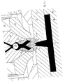
- the injection unit 1 is of the Mold 5 decoupled and the lower molding 58 from upper mold part 59 separated and the mold part 70 from the mold removed. That is vulcanized onto the molded part 70 End 71 can be seen that when separating from the spray channel 22nd or the discharge opening 24 and the injection opening 54 with has been pulled out. The spray channel 22 and the injection opening 54 are free of residues.
- the injection molding device is available for a new spraying process.
- the invention has the particular advantage that Coupling the injection unit with the mold of the Filling channel existing material is not affected.
- vulcanization of the material in the Filling channel can be avoided safely.
- the Material in the plasticizing unit 3 and in the filling channel 12 kept at the plasticizing temperature of about 70 ° C to 80 ° C.
- the material is then vulcanized in the mold required temperature of about 160 to 180 ° C heated. Due to the thermal separation of the mouth Filling channels from the dispensing opening become a thermal impairment of the material present in the filling channels avoided.
- the insert 16 is preferably made of a heat-insulating material Material made. Due to the spatial Separation will affect the material in the Filling channels avoided by temperature.
- the mouthpiece insert is 26 heat-insulating.
- the mouthpiece insert 26 from a heat insulating Material preferably CrNi steel such as V2A, V4A or ceramic made of sintered materials.
- the Inner surface of the mouthpiece insert 26 is a heat-insulating Coating on.
- the basic idea of the present invention is that of spatial and / or thermal separation of the material in the Filling channel 12 and in the spray channel 22.
- the invention Injection molding device has a simple and compact structure and is easy to use.
Landscapes
- Engineering & Computer Science (AREA)
- Manufacturing & Machinery (AREA)
- Mechanical Engineering (AREA)
- Injection Moulding Of Plastics Or The Like (AREA)
- Moulds For Moulding Plastics Or The Like (AREA)
- Materials For Medical Uses (AREA)
- Chemical Or Physical Treatment Of Fibers (AREA)
- Polarising Elements (AREA)
Applications Claiming Priority (3)
| Application Number | Priority Date | Filing Date | Title |
|---|---|---|---|
| DE19601556A DE19601556C2 (de) | 1996-01-17 | 1996-01-17 | Spritzgußvorrichtung für Gummi, Kautschuk oder ähnliche Werkstoffe |
| DE19601556 | 1996-01-17 | ||
| PCT/EP1997/000141 WO1997026125A1 (de) | 1996-01-17 | 1997-01-14 | Spritzgussvorrichtung |
Publications (2)
| Publication Number | Publication Date |
|---|---|
| EP0874723A1 EP0874723A1 (de) | 1998-11-04 |
| EP0874723B1 true EP0874723B1 (de) | 2002-04-10 |
Family
ID=7782994
Family Applications (1)
| Application Number | Title | Priority Date | Filing Date |
|---|---|---|---|
| EP97900602A Expired - Lifetime EP0874723B1 (de) | 1996-01-17 | 1997-01-14 | Spritzgussvorrichtung |
Country Status (16)
| Country | Link |
|---|---|
| US (1) | US6056537A (ko) |
| EP (1) | EP0874723B1 (ko) |
| JP (1) | JP3174346B2 (ko) |
| KR (1) | KR100312765B1 (ko) |
| CN (1) | CN1091024C (ko) |
| AT (1) | ATE215879T1 (ko) |
| AU (1) | AU1312097A (ko) |
| BR (1) | BR9707052A (ko) |
| CA (1) | CA2242372C (ko) |
| CZ (1) | CZ294486B6 (ko) |
| DE (2) | DE19601556C2 (ko) |
| ES (1) | ES2171879T3 (ko) |
| PL (1) | PL182128B1 (ko) |
| RU (1) | RU2164869C2 (ko) |
| TW (1) | TW402557B (ko) |
| WO (1) | WO1997026125A1 (ko) |
Families Citing this family (6)
| Publication number | Priority date | Publication date | Assignee | Title |
|---|---|---|---|---|
| DE19601556C2 (de) * | 1996-01-17 | 1999-08-05 | Alfred Steinl | Spritzgußvorrichtung für Gummi, Kautschuk oder ähnliche Werkstoffe |
| DE10315271B3 (de) * | 2003-04-03 | 2004-12-09 | Lwb Steinl Gmbh Landshuter Werkzeugbau | Vorrichtung und Verfahren zum Verbinden eines Spritzaggregats mit einem Kaltkanal eines Formwerkzeuges |
| WO2005074858A1 (en) * | 2004-02-04 | 2005-08-18 | Louis Olivier | Vibration generator and assemblies embodying same |
| JP4404728B2 (ja) * | 2004-09-14 | 2010-01-27 | 東海ゴム工業株式会社 | ゴム射出成形装置及びゴム製品の製造方法 |
| FR2921292B1 (fr) * | 2007-09-21 | 2012-09-21 | Rep Internat | Machine d'injection d'un materiau thermodurcissable, en particulier de vulcanisation de caoutchouc, et procede de mise en oeuvre correspondant |
| JP7297818B2 (ja) * | 2021-06-24 | 2023-06-26 | 日精樹脂工業株式会社 | 射出成形機及び射出成形方法 |
Family Cites Families (17)
| Publication number | Priority date | Publication date | Assignee | Title |
|---|---|---|---|---|
| DE141805C (ko) * | ||||
| US3295169A (en) * | 1963-12-23 | 1967-01-03 | Ernest P Moslo | Spring-pressed shutoff for injection nozzle |
| US3398436A (en) * | 1966-03-22 | 1968-08-27 | Inv S Finance Corp | Automatic regulator valve for injection moulding |
| DE1778033A1 (de) * | 1968-03-21 | 1971-07-15 | Boy Kg Dr | Einspritzduese fuer Spritzgussmaschinen |
| FR2080020A5 (en) * | 1970-02-20 | 1971-11-12 | Schlumberger Cie N | Screw injection moulding machine - with a variable head screw fitted with a back flow valve |
| US3723037A (en) * | 1970-11-04 | 1973-03-27 | Plastics Inc | Apparatus for injection molding articles from aminoplastic material |
| FR2242223A1 (en) * | 1973-09-04 | 1975-03-28 | Sacomat | Piston for injection moulding machines - with hollow body having central material transfer channel and peripheral annular lip |
| US3918870A (en) * | 1974-02-13 | 1975-11-11 | Norton Co | Injection molding machine |
| DE2835805A1 (de) * | 1978-08-16 | 1980-02-28 | Werner & Pfleiderer | Vorrichtung zur loesbaren verbindung einer spritzduese mit einem spritzzylinder |
| EP0010887A1 (en) * | 1978-10-16 | 1980-05-14 | Hooker Chemicals & Plastics Corp. | Method of plunger molding and plunger molding apparatus having temperature controlled runner and sprue portions |
| US4260359A (en) * | 1978-12-21 | 1981-04-07 | Hooker Chemicals & Plastics Corp. | Apparatus for runnerless injection molding thermosetting materials |
| CA1136815A (en) * | 1980-07-15 | 1982-12-07 | Jobst U. Gellert | Injection molding nozzle seal |
| DE3712325A1 (de) * | 1987-04-11 | 1988-10-27 | Steinl Landshuter Werkzeug | Vorrichtung zum spritzgiessen |
| FR2640907B1 (ko) * | 1988-12-22 | 1991-03-08 | Seva | |
| DE9110240U1 (de) * | 1991-08-19 | 1991-11-21 | Landshuter Werkzeugbau Alfred Steinl GmbH & Co KG, 8300 Landshut | Spritzgußvorrichtung |
| US5380186A (en) * | 1992-02-14 | 1995-01-10 | Hettinga; Siebolt | Flow regulating assembly for a plastic injection machine |
| DE19601556C2 (de) * | 1996-01-17 | 1999-08-05 | Alfred Steinl | Spritzgußvorrichtung für Gummi, Kautschuk oder ähnliche Werkstoffe |
-
1996
- 1996-01-17 DE DE19601556A patent/DE19601556C2/de not_active Expired - Fee Related
-
1997
- 1997-01-14 ES ES97900602T patent/ES2171879T3/es not_active Expired - Lifetime
- 1997-01-14 US US09/101,743 patent/US6056537A/en not_active Expired - Lifetime
- 1997-01-14 WO PCT/EP1997/000141 patent/WO1997026125A1/de not_active Ceased
- 1997-01-14 AT AT97900602T patent/ATE215879T1/de not_active IP Right Cessation
- 1997-01-14 CA CA002242372A patent/CA2242372C/en not_active Expired - Fee Related
- 1997-01-14 RU RU98115138/12A patent/RU2164869C2/ru not_active IP Right Cessation
- 1997-01-14 AU AU13120/97A patent/AU1312097A/en not_active Abandoned
- 1997-01-14 BR BR9707052-1A patent/BR9707052A/pt not_active IP Right Cessation
- 1997-01-14 PL PL97327822A patent/PL182128B1/pl not_active IP Right Cessation
- 1997-01-14 EP EP97900602A patent/EP0874723B1/de not_active Expired - Lifetime
- 1997-01-14 CN CN97191750A patent/CN1091024C/zh not_active Expired - Fee Related
- 1997-01-14 KR KR1019980705453A patent/KR100312765B1/ko not_active Expired - Fee Related
- 1997-01-14 DE DE59706963T patent/DE59706963D1/de not_active Expired - Lifetime
- 1997-01-14 JP JP52567197A patent/JP3174346B2/ja not_active Expired - Fee Related
- 1997-01-14 CZ CZ19982264A patent/CZ294486B6/cs not_active IP Right Cessation
- 1997-01-15 TW TW086100378A patent/TW402557B/zh not_active IP Right Cessation
Also Published As
| Publication number | Publication date |
|---|---|
| TW402557B (en) | 2000-08-21 |
| US6056537A (en) | 2000-05-02 |
| PL327822A1 (en) | 1999-01-04 |
| WO1997026125A1 (de) | 1997-07-24 |
| JP3174346B2 (ja) | 2001-06-11 |
| JPH11506712A (ja) | 1999-06-15 |
| KR100312765B1 (ko) | 2002-08-21 |
| AU1312097A (en) | 1997-08-11 |
| EP0874723A1 (de) | 1998-11-04 |
| CN1091024C (zh) | 2002-09-18 |
| CZ226498A3 (cs) | 1998-11-11 |
| PL182128B1 (en) | 2001-11-30 |
| ATE215879T1 (de) | 2002-04-15 |
| DE19601556A1 (de) | 1997-07-24 |
| KR19990077307A (ko) | 1999-10-25 |
| CA2242372C (en) | 2001-06-05 |
| CN1208370A (zh) | 1999-02-17 |
| CZ294486B6 (cs) | 2005-01-12 |
| BR9707052A (pt) | 1999-12-28 |
| DE19601556C2 (de) | 1999-08-05 |
| ES2171879T3 (es) | 2002-09-16 |
| CA2242372A1 (en) | 1997-07-24 |
| RU2164869C2 (ru) | 2001-04-10 |
| DE59706963D1 (de) | 2002-05-16 |
Similar Documents
| Publication | Publication Date | Title |
|---|---|---|
| DE69709941T2 (de) | Verfahren und vorrichtung zur herstellung eines tamponapplikators für frauenhygiene | |
| DE4414258C2 (de) | Verfahren zum Spritzgießen von mindestens aus zwei unterschiedlichen Schichten bestehenden Gegenständen | |
| DE69524797T2 (de) | Abdichtungsbüchse für Ventil im Spritzgiessen mit dünnem Kragenteil | |
| EP0671249B1 (de) | Verfahren und Vorrichtung zur Herstellung optischen Linsen | |
| DE69919809T2 (de) | Mikrospritzgiessmaschine | |
| EP1771290B1 (de) | Spritzgiessmaschine und verfahren zum spritzgiessen | |
| AT5750U1 (de) | Einspritzdüse für kautschuk, gummi und polysiloxane | |
| DE3121428C2 (de) | Spritzgießvorrichtung für plastifizierbare Massen, insbesondere mit Verstärkungsfasern | |
| EP0595158B1 (de) | Verfahren und Vorrichtung zum Herstellen von Hohlkörpern aus thermoplastischem Kunststoff | |
| EP2205419A1 (de) | Angussadapter sowie angusssystem für einen angussadapter | |
| EP0874723B1 (de) | Spritzgussvorrichtung | |
| EP0846050B1 (de) | Spritzgiessmaschine mit integriertem heisskanalsystem | |
| DE69627824T2 (de) | Verfahren und vorrichtung zum herstellen von rohrfoermigen behaeltern mit verschlussvorrichtung | |
| DE4014244C2 (ko) | ||
| DE69114258T2 (de) | Düsevorrichtung zum spritzgiessen. | |
| DE3143748C2 (de) | Form zum Spritzgießen oder Preßspritzen von Kautschuk oder anderen plastischen, wärmehärtbaren Werkstoffen | |
| EP3524402B1 (de) | Nadelverschlussdüse mit separatem nadelkanal und schmelzekanal | |
| DE3324204A1 (de) | Verfahren und vorrichtung zum mindestens zweistufigen spritzgiessen von zusammengesetzten formkoerpern aus polymeren sowie anwendung des verfahrens | |
| EP0287001B1 (de) | Vorrichtung zum Spritzgiessen | |
| DE2542875A1 (de) | Verfahren zum angusslosen spritzen von thermoplastteilen | |
| EP1410891A1 (de) | Kaltkanal-Verschlussdüse für das Spritzgiessen von Elastomeren | |
| DE1124234B (de) | Spritzgussmaschine zur Verarbeitung thermoplastischer Kunststoffe | |
| DE10013920A1 (de) | Spritzgießwerkzeug | |
| DE10321355A1 (de) | Düse | |
| DE10113352B4 (de) | Verschließbarer Düsenkörper sowie Verfahren zum Verschluss desselben |
Legal Events
| Date | Code | Title | Description |
|---|---|---|---|
| PUAI | Public reference made under article 153(3) epc to a published international application that has entered the european phase |
Free format text: ORIGINAL CODE: 0009012 |
|
| 17P | Request for examination filed |
Effective date: 19980812 |
|
| AK | Designated contracting states |
Kind code of ref document: A1 Designated state(s): AT BE CH DE DK ES FI FR GB GR IE IT LI LU MC NL PT SE |
|
| 17Q | First examination report despatched |
Effective date: 20000124 |
|
| GRAG | Despatch of communication of intention to grant |
Free format text: ORIGINAL CODE: EPIDOS AGRA |
|
| GRAG | Despatch of communication of intention to grant |
Free format text: ORIGINAL CODE: EPIDOS AGRA |
|
| GRAH | Despatch of communication of intention to grant a patent |
Free format text: ORIGINAL CODE: EPIDOS IGRA |
|
| REG | Reference to a national code |
Ref country code: GB Ref legal event code: IF02 |
|
| GRAH | Despatch of communication of intention to grant a patent |
Free format text: ORIGINAL CODE: EPIDOS IGRA |
|
| GRAA | (expected) grant |
Free format text: ORIGINAL CODE: 0009210 |
|
| AK | Designated contracting states |
Kind code of ref document: B1 Designated state(s): AT BE CH DE DK ES FI FR GB GR IE IT LI LU MC NL PT SE |
|
| PG25 | Lapsed in a contracting state [announced via postgrant information from national office to epo] |
Ref country code: GR Free format text: LAPSE BECAUSE OF FAILURE TO SUBMIT A TRANSLATION OF THE DESCRIPTION OR TO PAY THE FEE WITHIN THE PRESCRIBED TIME-LIMIT Effective date: 20020410 |
|
| REF | Corresponds to: |
Ref document number: 215879 Country of ref document: AT Date of ref document: 20020415 Kind code of ref document: T |
|
| REG | Reference to a national code |
Ref country code: CH Ref legal event code: EP |
|
| REG | Reference to a national code |
Ref country code: CH Ref legal event code: NV Representative=s name: BOVARD AG PATENTANWAELTE Ref country code: IE Ref legal event code: FG4D Free format text: GERMAN |
|
| REF | Corresponds to: |
Ref document number: 59706963 Country of ref document: DE Date of ref document: 20020516 |
|
| PG25 | Lapsed in a contracting state [announced via postgrant information from national office to epo] |
Ref country code: PT Free format text: LAPSE BECAUSE OF FAILURE TO SUBMIT A TRANSLATION OF THE DESCRIPTION OR TO PAY THE FEE WITHIN THE PRESCRIBED TIME-LIMIT Effective date: 20020710 Ref country code: DK Free format text: LAPSE BECAUSE OF FAILURE TO SUBMIT A TRANSLATION OF THE DESCRIPTION OR TO PAY THE FEE WITHIN THE PRESCRIBED TIME-LIMIT Effective date: 20020710 |
|
| GBT | Gb: translation of ep patent filed (gb section 77(6)(a)/1977) |
Effective date: 20020703 |
|
| REG | Reference to a national code |
Ref country code: ES Ref legal event code: FG2A Ref document number: 2171879 Country of ref document: ES Kind code of ref document: T3 |
|
| ET | Fr: translation filed | ||
| PG25 | Lapsed in a contracting state [announced via postgrant information from national office to epo] |
Ref country code: LU Free format text: LAPSE BECAUSE OF NON-PAYMENT OF DUE FEES Effective date: 20030114 |
|
| PG25 | Lapsed in a contracting state [announced via postgrant information from national office to epo] |
Ref country code: MC Free format text: LAPSE BECAUSE OF NON-PAYMENT OF DUE FEES Effective date: 20030131 Ref country code: BE Free format text: LAPSE BECAUSE OF NON-PAYMENT OF DUE FEES Effective date: 20030131 |
|
| PLBE | No opposition filed within time limit |
Free format text: ORIGINAL CODE: 0009261 |
|
| STAA | Information on the status of an ep patent application or granted ep patent |
Free format text: STATUS: NO OPPOSITION FILED WITHIN TIME LIMIT |
|
| 26N | No opposition filed |
Effective date: 20030113 |
|
| PGFP | Annual fee paid to national office [announced via postgrant information from national office to epo] |
Ref country code: IE Payment date: 20090126 Year of fee payment: 13 Ref country code: ES Payment date: 20090116 Year of fee payment: 13 Ref country code: AT Payment date: 20090122 Year of fee payment: 13 |
|
| PGFP | Annual fee paid to national office [announced via postgrant information from national office to epo] |
Ref country code: NL Payment date: 20090127 Year of fee payment: 13 Ref country code: FI Payment date: 20090123 Year of fee payment: 13 |
|
| PGFP | Annual fee paid to national office [announced via postgrant information from national office to epo] |
Ref country code: GB Payment date: 20090122 Year of fee payment: 13 Ref country code: CH Payment date: 20090130 Year of fee payment: 13 |
|
| PGFP | Annual fee paid to national office [announced via postgrant information from national office to epo] |
Ref country code: SE Payment date: 20090120 Year of fee payment: 13 Ref country code: IT Payment date: 20090126 Year of fee payment: 13 |
|
| REG | Reference to a national code |
Ref country code: NL Ref legal event code: V1 Effective date: 20100801 |
|
| REG | Reference to a national code |
Ref country code: CH Ref legal event code: PL |
|
| GBPC | Gb: european patent ceased through non-payment of renewal fee |
Effective date: 20100114 |
|
| EUG | Se: european patent has lapsed | ||
| REG | Reference to a national code |
Ref country code: IE Ref legal event code: MM4A |
|
| PG25 | Lapsed in a contracting state [announced via postgrant information from national office to epo] |
Ref country code: NL Free format text: LAPSE BECAUSE OF NON-PAYMENT OF DUE FEES Effective date: 20100801 Ref country code: LI Free format text: LAPSE BECAUSE OF NON-PAYMENT OF DUE FEES Effective date: 20100131 Ref country code: CH Free format text: LAPSE BECAUSE OF NON-PAYMENT OF DUE FEES Effective date: 20100131 |
|
| PG25 | Lapsed in a contracting state [announced via postgrant information from national office to epo] |
Ref country code: FI Free format text: LAPSE BECAUSE OF NON-PAYMENT OF DUE FEES Effective date: 20100114 Ref country code: AT Free format text: LAPSE BECAUSE OF NON-PAYMENT OF DUE FEES Effective date: 20100114 |
|
| PG25 | Lapsed in a contracting state [announced via postgrant information from national office to epo] |
Ref country code: GB Free format text: LAPSE BECAUSE OF NON-PAYMENT OF DUE FEES Effective date: 20100114 |
|
| PG25 | Lapsed in a contracting state [announced via postgrant information from national office to epo] |
Ref country code: IE Free format text: LAPSE BECAUSE OF NON-PAYMENT OF DUE FEES Effective date: 20100114 |
|
| REG | Reference to a national code |
Ref country code: ES Ref legal event code: FD2A Effective date: 20110324 |
|
| PG25 | Lapsed in a contracting state [announced via postgrant information from national office to epo] |
Ref country code: IT Free format text: LAPSE BECAUSE OF NON-PAYMENT OF DUE FEES Effective date: 20100114 |
|
| PG25 | Lapsed in a contracting state [announced via postgrant information from national office to epo] |
Ref country code: ES Free format text: LAPSE BECAUSE OF NON-PAYMENT OF DUE FEES Effective date: 20110310 |
|
| PG25 | Lapsed in a contracting state [announced via postgrant information from national office to epo] |
Ref country code: ES Free format text: LAPSE BECAUSE OF NON-PAYMENT OF DUE FEES Effective date: 20100115 |
|
| PG25 | Lapsed in a contracting state [announced via postgrant information from national office to epo] |
Ref country code: SE Free format text: LAPSE BECAUSE OF NON-PAYMENT OF DUE FEES Effective date: 20100115 |
|
| REG | Reference to a national code |
Ref country code: FR Ref legal event code: PLFP Year of fee payment: 19 |
|
| PGFP | Annual fee paid to national office [announced via postgrant information from national office to epo] |
Ref country code: DE Payment date: 20150226 Year of fee payment: 19 |
|
| PGFP | Annual fee paid to national office [announced via postgrant information from national office to epo] |
Ref country code: FR Payment date: 20150119 Year of fee payment: 19 |
|
| REG | Reference to a national code |
Ref country code: DE Ref legal event code: R119 Ref document number: 59706963 Country of ref document: DE |
|
| REG | Reference to a national code |
Ref country code: FR Ref legal event code: ST Effective date: 20160930 |
|
| PG25 | Lapsed in a contracting state [announced via postgrant information from national office to epo] |
Ref country code: DE Free format text: LAPSE BECAUSE OF NON-PAYMENT OF DUE FEES Effective date: 20160802 |
|
| PG25 | Lapsed in a contracting state [announced via postgrant information from national office to epo] |
Ref country code: FR Free format text: LAPSE BECAUSE OF NON-PAYMENT OF DUE FEES Effective date: 20160201 |