EP0875948A1 - Vorrichtung zum Zusammenbau von elektrochemischen Generatoren in einer Batterie - Google Patents
Vorrichtung zum Zusammenbau von elektrochemischen Generatoren in einer Batterie Download PDFInfo
- Publication number
- EP0875948A1 EP0875948A1 EP98401025A EP98401025A EP0875948A1 EP 0875948 A1 EP0875948 A1 EP 0875948A1 EP 98401025 A EP98401025 A EP 98401025A EP 98401025 A EP98401025 A EP 98401025A EP 0875948 A1 EP0875948 A1 EP 0875948A1
- Authority
- EP
- European Patent Office
- Prior art keywords
- generators
- elements
- edge
- assembly
- tab
- Prior art date
- Legal status (The legal status is an assumption and is not a legal conclusion. Google has not performed a legal analysis and makes no representation as to the accuracy of the status listed.)
- Granted
Links
Images

Classifications
-
- H—ELECTRICITY
- H01—ELECTRIC ELEMENTS
- H01M—PROCESSES OR MEANS, e.g. BATTERIES, FOR THE DIRECT CONVERSION OF CHEMICAL ENERGY INTO ELECTRICAL ENERGY
- H01M6/00—Primary cells; Manufacture thereof
- H01M6/42—Grouping of primary cells into batteries
- H01M6/44—Grouping of primary cells into batteries of tubular or cup-shaped cells
-
- H—ELECTRICITY
- H01—ELECTRIC ELEMENTS
- H01M—PROCESSES OR MEANS, e.g. BATTERIES, FOR THE DIRECT CONVERSION OF CHEMICAL ENERGY INTO ELECTRICAL ENERGY
- H01M50/00—Constructional details or processes of manufacture of the non-active parts of electrochemical cells other than fuel cells, e.g. hybrid cells
- H01M50/20—Mountings; Secondary casings or frames; Racks, modules or packs; Suspension devices; Shock absorbers; Transport or carrying devices; Holders
- H01M50/204—Racks, modules or packs for multiple batteries or multiple cells
- H01M50/207—Racks, modules or packs for multiple batteries or multiple cells characterised by their shape
- H01M50/213—Racks, modules or packs for multiple batteries or multiple cells characterised by their shape adapted for cells having curved cross-section, e.g. round or elliptic
-
- Y—GENERAL TAGGING OF NEW TECHNOLOGICAL DEVELOPMENTS; GENERAL TAGGING OF CROSS-SECTIONAL TECHNOLOGIES SPANNING OVER SEVERAL SECTIONS OF THE IPC; TECHNICAL SUBJECTS COVERED BY FORMER USPC CROSS-REFERENCE ART COLLECTIONS [XRACs] AND DIGESTS
- Y02—TECHNOLOGIES OR APPLICATIONS FOR MITIGATION OR ADAPTATION AGAINST CLIMATE CHANGE
- Y02E—REDUCTION OF GREENHOUSE GAS [GHG] EMISSIONS, RELATED TO ENERGY GENERATION, TRANSMISSION OR DISTRIBUTION
- Y02E60/00—Enabling technologies; Technologies with a potential or indirect contribution to GHG emissions mitigation
- Y02E60/10—Energy storage using batteries
Definitions
- the present invention relates to a device battery assembly of electrochemical generators, such only batteries.
- Another solution is to put the battery between two flanges placed at the ends.
- the flanges can be glued or forcibly assembled at said ends, in which case the mechanical strength of the assembly remains insufficient, or an attachment can ensure the mechanical connection between the flanges, which complicates the assembly and multiplies the necessary parts.
- Document US-A-4 806 440 discloses a battery assembly device for four generators cylindrical electrochemicals, arranged side by side, comprising two elements each constituting a support base from the end of said generators; one of the two has elongated connecting legs with the other element ; the two elements include organs carrying means complementary ratchets cooperating to maintain the assembly of the two elements at the ends of said generators.
- the cost of this solution is high from makes the two elements different and requires two injection molds, different storage and marking for setting up.
- Document DE-2 805 067 describes a device for the columnar assembly of cylindrical objects of same diameter.
- This device consists of two elements identical each comprising a support base at the end generators and one or more longitudinal walls provided with longitudinal recesses, the walls being reinforced on their inner side. Both elements have centering members, the connection with the other element being obtained in particular by welding. In case of heavy loads or shock, the mechanical strength of this assembly of electrochemical generators is insufficient.
- JP-A-6 243 849 and JP-A-8 203 488 are also know different assembly elements.
- the object of the invention is to remedy these disadvantages and to propose a new device for the battery charging or other generators electrochemical, this device being compact and low cost.
- this device must allow the exit of wires and connectors and ensure good mechanical support drums.
- it must be removable.
- each of said elements includes a support base for the end of said generators, said base being formed by a bottom surrounded by a edge, at least one elongated connecting leg with the other element integral with said edge from which it originates perpendicularly, complementary means cooperating to maintain the assembly of the two elements at the ends said generators, said complementary means consisting in a projection formed on the leg of one of said elements in a direction substantially perpendicular to the direction assembly and a recess in the edge of the other element receiving said projection to achieve a snap.
- the edge advantageously comprises a notch for the passage of electrical connections.
- the output of the wires can be done axially or radially.
- the two pieces necessary to maintain a battery are strictly identical and can be made of semi-rigid plastic by injection in a single mold.
- the support and linkage system conforms to the invention, external to the battery, is remarkable in that that it occupies little or no space outside the envelope volume drums.
- the empty volume formed inside said volume-envelope allows the possible inclusion of security or other components (electronic components, son, etc.).
- the internal face of the tab is shaped so as to further increase the free volume.
- the device can be adapted to any number of generators. In the most preferred embodiment simple, it allows two cylindrical generators to be assembled.
- the background of the elements has substantially the shape of a rectangle with rounded corners and a single leg per element is sufficient to provide good mechanical support.
- the bottom has the shape of a square with rounded angles, and we can predict a single leg, or two legs arranged on two sides of the square.
- the invention adapts to various forms (cylindrical, prismatic) and sizes of the generators.
- Figure 1 shows an exploded perspective view of two batteries intended to be maintained by two identical elements according to the invention.
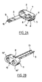
- Figures 2A and 2B show in perspective two of these identical elements, respectively in one direction and in the other, as they appear to form the assembly according to the invention.
- Each holding element preferably made by semi-rigid plastic molding electrically insulating, includes a housing base 2 and a connecting tab and latching 3.
- the base 2 consists of an elongated bottom 4, surrounded by an edge 5, for example 5 to 10 mm high.
- the bottom and the edge are shaped to accommodate practically without clearance the end of two contiguous cylindrical stacks 6, and could possibly have a slight concavity on their long sides 7.
- the leg 3 forming a body with the edge 5, leaves perpendicularly from it, preferably in the middle of a long side, because the batteries leave enough space for the flexing of the tab 3 when it snaps into the opposite element.
- the leg is much longer than the edge height.
- the length of the leg increased by the height of the edges located at each end is equal to the height of the electrochemical cells to be assembled, either by example for AA format generators a total height about 62mm.
- the edge 5 of the base has a recess 8 on its internal wall, in the middle on the long side opposite to that from which the leg 3 leaves.
- recess 8 can receive a corresponding projection 9 formed towards the end of tab 3, if necessary in a recess 10.
- the projection 9 has a shape such that once blocked in the recess 8, the face external of the device is practically flat.
- the ratchet is absolutely removable from the outside. But, even with a through recess as shown, the disassembly without tools is difficult given the rigidity of the paw.
- the edge 5 includes a notch 11 intended for the radial passage of connections.
- An axial outlet, such as the opening 12 made in the bottom 4, can also be planned.
- the tab 3 has a form of gutter 13 on its internal face, which constitutes a volume available to optionally include components or other devices (electronic components, wires, etc.)
- bosses 14 (FIG. 2A) on the bottom 4 intended to wedge the batteries (these bosses correspond to the depressions 14 ′ in FIG. 2B).
- the mold can be adapted the production of devices suitable for generators of different heights.
- the device according to the invention has multiple advantages compared to known devices.
Landscapes
- Chemical & Material Sciences (AREA)
- Chemical Kinetics & Catalysis (AREA)
- Electrochemistry (AREA)
- General Chemical & Material Sciences (AREA)
- Engineering & Computer Science (AREA)
- Manufacturing & Machinery (AREA)
- Battery Mounting, Suspending (AREA)
- Connection Of Batteries Or Terminals (AREA)
Applications Claiming Priority (2)
| Application Number | Priority Date | Filing Date | Title |
|---|---|---|---|
| FR9705206 | 1997-04-28 | ||
| FR9705206A FR2762716B1 (fr) | 1997-04-28 | 1997-04-28 | Dispositif d'assemblage en batterie de generateurs electrochimiques |
Publications (2)
| Publication Number | Publication Date |
|---|---|
| EP0875948A1 true EP0875948A1 (de) | 1998-11-04 |
| EP0875948B1 EP0875948B1 (de) | 2002-07-03 |
Family
ID=9506364
Family Applications (1)
| Application Number | Title | Priority Date | Filing Date |
|---|---|---|---|
| EP98401025A Expired - Lifetime EP0875948B1 (de) | 1997-04-28 | 1998-04-27 | Vorrichtung zum Zusammenbau von elektrochemischen Generatoren in einer Batterie |
Country Status (5)
| Country | Link |
|---|---|
| US (1) | US6218042B1 (de) |
| EP (1) | EP0875948B1 (de) |
| JP (1) | JPH1173932A (de) |
| DE (1) | DE69806307T2 (de) |
| FR (1) | FR2762716B1 (de) |
Cited By (4)
| Publication number | Priority date | Publication date | Assignee | Title |
|---|---|---|---|---|
| WO2000046865A1 (en) * | 1999-02-01 | 2000-08-10 | Matsushita Electric Industrial Co., Ltd. | Battery pack |
| EP1069631A1 (de) * | 1999-07-15 | 2001-01-17 | Black & Decker Inc. | Batteriepack und Verfahren zu dessen Herstellung |
| EP2426752A3 (de) * | 2010-09-01 | 2012-07-11 | SB LiMotive Co., Ltd. | Wiederaufladbare Batterie |
| EP3547393A1 (de) * | 2018-03-30 | 2019-10-02 | Acer Incorporated | Träger und batterieanordnung |
Families Citing this family (18)
| Publication number | Priority date | Publication date | Assignee | Title |
|---|---|---|---|---|
| US6303248B1 (en) * | 1997-06-10 | 2001-10-16 | Roland K. Peterson | Solderless battery pack |
| US6811922B2 (en) * | 2002-04-11 | 2004-11-02 | Eveready Battery Company, Inc. | Battery pack |
| USD488370S1 (en) | 2003-03-07 | 2004-04-13 | American Megatrends, Inc. | Retainer clip |
| US8734983B2 (en) * | 2004-04-14 | 2014-05-27 | Inventek Corporation | Housing for electrochemical devices |
| DE202004015371U1 (de) * | 2004-10-04 | 2006-02-09 | Zumtobel Staff Gmbh | Halteelement für eine Batterie oder einen Akkumulator |
| US7694419B2 (en) * | 2005-04-27 | 2010-04-13 | The Gillette Company | Battery-operated appliances |
| DE102007010741B4 (de) * | 2007-02-27 | 2012-05-24 | Daimler Ag | Batterie mit Gehäuse und spielfrei eingebautem Zellverbund sowie Verwendung als Fahrzeugbatterie |
| USD631829S1 (en) * | 2008-10-14 | 2011-02-01 | Boston-Power, Inc. | Battery pack |
| USD631826S1 (en) * | 2008-10-14 | 2011-02-01 | Boston-Power, Inc. | Battery pack |
| USD631828S1 (en) * | 2008-10-14 | 2011-02-01 | Boston-Power, Inc. | Battery pack |
| USD631827S1 (en) * | 2008-10-14 | 2011-02-01 | Boston-Power, Inc. | Battery pack |
| USD631831S1 (en) * | 2008-10-14 | 2011-02-01 | Boston-Power, Inc. | Battery pack |
| USD631825S1 (en) * | 2008-10-14 | 2011-02-01 | Boston-Power, Inc. | Battery pack |
| USD631833S1 (en) * | 2008-10-14 | 2011-02-01 | Boston-Power, Inc. | Battery pack |
| USD631830S1 (en) * | 2008-10-14 | 2011-02-01 | Boston-Power, Inc. | Battery pack |
| USD631832S1 (en) * | 2008-10-14 | 2011-02-01 | Boston-Power, Inc. | Battery pack |
| US9362536B2 (en) * | 2012-04-25 | 2016-06-07 | Robert Bosch Gmbh | Optimized module restraint system |
| CN109402127B (zh) * | 2018-09-29 | 2021-12-10 | 复旦大学附属眼耳鼻喉科医院 | 一组与结缔组织生长因子特异性结合的高亲和力核酸适配体及其应用 |
Citations (8)
| Publication number | Priority date | Publication date | Assignee | Title |
|---|---|---|---|---|
| DE2805067A1 (de) * | 1978-02-07 | 1979-08-09 | Electron Gmbh Vertrieb Elektro | Gehaeuse zur saeulenfoermigen zusammenfassung kreiszylindrischer gegenstaende gleichen durchmessers |
| JPS58225557A (ja) * | 1982-06-23 | 1983-12-27 | Canon Inc | 電池パツク |
| JPS642250A (en) * | 1987-06-24 | 1989-01-06 | Sanyo Electric Co Ltd | Battery pack |
| US4806440A (en) * | 1987-02-05 | 1989-02-21 | Cni | Lantern battery substitute |
| JPH0224959A (ja) * | 1988-07-12 | 1990-01-26 | Sony Corp | 電池ホルダ |
| JPH07105921A (ja) * | 1993-10-01 | 1995-04-21 | Matsushita Electric Ind Co Ltd | 電池パック |
| FR2737807A3 (fr) * | 1995-08-07 | 1997-02-14 | Aeg Mobile Communication | Bloc d'accumulateurs |
| DE29712550U1 (de) * | 1997-07-16 | 1997-09-11 | Fürschbach, Bernd, 29690 Schwarmstedt | Stromversorgungseinheit für Warenautomaten |
Family Cites Families (2)
| Publication number | Priority date | Publication date | Assignee | Title |
|---|---|---|---|---|
| JPH0690921B2 (ja) * | 1988-09-28 | 1994-11-14 | 松下電器産業株式会社 | パック電池とその製造法 |
| US5709963A (en) * | 1996-07-25 | 1998-01-20 | Daewoo Electronics Co., Inc. | Battery pack |
-
1997
- 1997-04-28 FR FR9705206A patent/FR2762716B1/fr not_active Expired - Fee Related
-
1998
- 1998-04-27 EP EP98401025A patent/EP0875948B1/de not_active Expired - Lifetime
- 1998-04-27 US US09/066,567 patent/US6218042B1/en not_active Expired - Fee Related
- 1998-04-27 DE DE69806307T patent/DE69806307T2/de not_active Expired - Lifetime
- 1998-04-28 JP JP10119104A patent/JPH1173932A/ja active Pending
Patent Citations (8)
| Publication number | Priority date | Publication date | Assignee | Title |
|---|---|---|---|---|
| DE2805067A1 (de) * | 1978-02-07 | 1979-08-09 | Electron Gmbh Vertrieb Elektro | Gehaeuse zur saeulenfoermigen zusammenfassung kreiszylindrischer gegenstaende gleichen durchmessers |
| JPS58225557A (ja) * | 1982-06-23 | 1983-12-27 | Canon Inc | 電池パツク |
| US4806440A (en) * | 1987-02-05 | 1989-02-21 | Cni | Lantern battery substitute |
| JPS642250A (en) * | 1987-06-24 | 1989-01-06 | Sanyo Electric Co Ltd | Battery pack |
| JPH0224959A (ja) * | 1988-07-12 | 1990-01-26 | Sony Corp | 電池ホルダ |
| JPH07105921A (ja) * | 1993-10-01 | 1995-04-21 | Matsushita Electric Ind Co Ltd | 電池パック |
| FR2737807A3 (fr) * | 1995-08-07 | 1997-02-14 | Aeg Mobile Communication | Bloc d'accumulateurs |
| DE29712550U1 (de) * | 1997-07-16 | 1997-09-11 | Fürschbach, Bernd, 29690 Schwarmstedt | Stromversorgungseinheit für Warenautomaten |
Non-Patent Citations (5)
| Title |
|---|
| DATABASE WPI Derwent World Patents Index; AN 95-188558, XP002052128 * |
| PATENT ABSTRACTS OF JAPAN vol. 008, no. 078 (E - 237) 10 April 1984 (1984-04-10) * |
| PATENT ABSTRACTS OF JAPAN vol. 013, no. 168 (E - 747) 21 April 1989 (1989-04-21) * |
| PATENT ABSTRACTS OF JAPAN vol. 014, no. 168 (E - 0912) 30 March 1990 (1990-03-30) * |
| PATENT ABSTRACTS OF JAPAN vol. 095, no. 007 31 August 1995 (1995-08-31) * |
Cited By (7)
| Publication number | Priority date | Publication date | Assignee | Title |
|---|---|---|---|---|
| WO2000046865A1 (en) * | 1999-02-01 | 2000-08-10 | Matsushita Electric Industrial Co., Ltd. | Battery pack |
| US6440601B1 (en) | 1999-02-01 | 2002-08-27 | Matsushita Electric Industrial Co., Ltd. | Battery pack |
| EP1069631A1 (de) * | 1999-07-15 | 2001-01-17 | Black & Decker Inc. | Batteriepack und Verfahren zu dessen Herstellung |
| US6627345B1 (en) | 1999-07-15 | 2003-09-30 | Black & Decker Inc. | Battery pack |
| EP2426752A3 (de) * | 2010-09-01 | 2012-07-11 | SB LiMotive Co., Ltd. | Wiederaufladbare Batterie |
| EP3547393A1 (de) * | 2018-03-30 | 2019-10-02 | Acer Incorporated | Träger und batterieanordnung |
| US11043712B2 (en) | 2018-03-30 | 2021-06-22 | Acer Incorporated | Carrier and battery assembly |
Also Published As
| Publication number | Publication date |
|---|---|
| FR2762716B1 (fr) | 1999-05-28 |
| JPH1173932A (ja) | 1999-03-16 |
| FR2762716A1 (fr) | 1998-10-30 |
| DE69806307T2 (de) | 2003-02-20 |
| EP0875948B1 (de) | 2002-07-03 |
| US6218042B1 (en) | 2001-04-17 |
| DE69806307D1 (de) | 2002-08-08 |
Similar Documents
| Publication | Publication Date | Title |
|---|---|---|
| EP0875948B1 (de) | Vorrichtung zum Zusammenbau von elektrochemischen Generatoren in einer Batterie | |
| EP0996180B1 (de) | Knopfzellenträger mit vertikaler Positionierung | |
| EP1537630A2 (de) | Elektrischer anschlusskontakt mit elastischem kontaktblatt | |
| FR2988914A3 (fr) | Structure de module de batterie a assemblage simplifie pour cellules li-ion a enveloppe souple et un module correspondant | |
| FR2934092A1 (fr) | Ensemble de connexion et procede de montage d'un tel ensemble de connexion | |
| EP2751820A1 (de) | Verbinderanordnung zwischen zwei zylindrischen energiespeicherunganordnungen | |
| EP4327395A1 (de) | Abgedichtetes gehäuse für elektrische batterie | |
| EP2760708B1 (de) | Hupe mit einem verbesserten anschlussystem | |
| FR2763755A1 (fr) | Ensemble reglable en plastique de maintien d'elements tels que des boitiers d'appareillage electrique entre des banches | |
| WO2021058213A1 (fr) | Dispositif de connexion carrure-corne pour une montre | |
| FR3047050A1 (fr) | Systeme de type modulaire | |
| EP3255732B1 (de) | Elektrische verbindungsklemme, die einen verbindungshebel umfasst, und entsprechende elektrische geräte | |
| FR2679378A1 (fr) | Fusible electrique pour courants forts. | |
| FR2638219A1 (fr) | Lampe de poche miniaturisee du type comportant un boitier d'epaisseur faible par rapport a ses autres dimensions | |
| FR2790879A1 (fr) | Ensemble reglable et verrouillable en plastique de maintien d'elements tels que des boitiers d'appareillage electrique entre des banches | |
| FR2716298A1 (fr) | Perfectionnements aux connecteurs électriques. | |
| FR2619170A1 (fr) | Dispositif permettant d'assembler deux corps l'un avec l'autre et procede de realisation de ce produit | |
| EP3844405B1 (de) | Vorrichtung zum verbinden von rohrförmigen elementen | |
| EP0865639B1 (de) | Gehäuse für eine läsbare einsteckkarte mit erweitertem format | |
| FR2868618A1 (fr) | Ensemble reglable indexable en plastique de maintien d'elements tels que des boitiers d'appareillage electrique entre des banches | |
| FR2761208A1 (fr) | Ensemble monobloc en plastique de maintien d'elements tels que des boitiers d'appareillage electrique entre des banches | |
| FR2678423A1 (fr) | Boitier pour un appareillage electrique. | |
| FR2780205A1 (fr) | Dispositif de liaison d'un conducteur electrique de derivation sur un conducteur principal | |
| FR3137488A1 (fr) | Dispositif de dissipation de chaleur amovible ameliore, destine a etre monte de maniere reversible sur un corps lateral d’un emballage de transport et/ou d’entreposage de matieres radioactives | |
| FR2812135A1 (fr) | Ensemble reglable et verrouillable en plastique de maintien d'elements tels que des boitiers d'appareillage electrique entre des banches |
Legal Events
| Date | Code | Title | Description |
|---|---|---|---|
| PUAI | Public reference made under article 153(3) epc to a published international application that has entered the european phase |
Free format text: ORIGINAL CODE: 0009012 |
|
| AK | Designated contracting states |
Kind code of ref document: A1 Designated state(s): DE FR GB IT |
|
| AX | Request for extension of the european patent |
Free format text: AL;LT;LV;MK;RO;SI |
|
| RAP3 | Party data changed (applicant data changed or rights of an application transferred) |
Owner name: ALCATEL |
|
| RAP3 | Party data changed (applicant data changed or rights of an application transferred) |
Owner name: ALCATEL |
|
| 17P | Request for examination filed |
Effective date: 19990504 |
|
| AKX | Designation fees paid |
Free format text: DE FR GB IT |
|
| GRAG | Despatch of communication of intention to grant |
Free format text: ORIGINAL CODE: EPIDOS AGRA |
|
| 17Q | First examination report despatched |
Effective date: 20010813 |
|
| GRAG | Despatch of communication of intention to grant |
Free format text: ORIGINAL CODE: EPIDOS AGRA |
|
| GRAH | Despatch of communication of intention to grant a patent |
Free format text: ORIGINAL CODE: EPIDOS IGRA |
|
| GRAH | Despatch of communication of intention to grant a patent |
Free format text: ORIGINAL CODE: EPIDOS IGRA |
|
| GRAA | (expected) grant |
Free format text: ORIGINAL CODE: 0009210 |
|
| AK | Designated contracting states |
Kind code of ref document: B1 Designated state(s): DE FR GB IT |
|
| PG25 | Lapsed in a contracting state [announced via postgrant information from national office to epo] |
Ref country code: IT Free format text: LAPSE BECAUSE OF FAILURE TO SUBMIT A TRANSLATION OF THE DESCRIPTION OR TO PAY THE FEE WITHIN THE PRESCRIBED TIME-LIMIT;WARNING: LAPSES OF ITALIAN PATENTS WITH EFFECTIVE DATE BEFORE 2007 MAY HAVE OCCURRED AT ANY TIME BEFORE 2007. THE CORRECT EFFECTIVE DATE MAY BE DIFFERENT FROM THE ONE RECORDED. Effective date: 20020703 |
|
| GBT | Gb: translation of ep patent filed (gb section 77(6)(a)/1977) |
Effective date: 20020703 |
|
| REF | Corresponds to: |
Ref document number: 69806307 Country of ref document: DE Date of ref document: 20020808 |
|
| PLBE | No opposition filed within time limit |
Free format text: ORIGINAL CODE: 0009261 |
|
| STAA | Information on the status of an ep patent application or granted ep patent |
Free format text: STATUS: NO OPPOSITION FILED WITHIN TIME LIMIT |
|
| 26N | No opposition filed |
Effective date: 20030404 |
|
| REG | Reference to a national code |
Ref country code: GB Ref legal event code: 732E |
|
| REG | Reference to a national code |
Ref country code: FR Ref legal event code: TP |
|
| PGFP | Annual fee paid to national office [announced via postgrant information from national office to epo] |
Ref country code: DE Payment date: 20110404 Year of fee payment: 14 Ref country code: GB Payment date: 20110330 Year of fee payment: 14 Ref country code: FR Payment date: 20110419 Year of fee payment: 14 |
|
| GBPC | Gb: european patent ceased through non-payment of renewal fee |
Effective date: 20120427 |
|
| REG | Reference to a national code |
Ref country code: FR Ref legal event code: ST Effective date: 20121228 |
|
| PG25 | Lapsed in a contracting state [announced via postgrant information from national office to epo] |
Ref country code: GB Free format text: LAPSE BECAUSE OF NON-PAYMENT OF DUE FEES Effective date: 20120427 |
|
| REG | Reference to a national code |
Ref country code: DE Ref legal event code: R119 Ref document number: 69806307 Country of ref document: DE Effective date: 20121101 |
|
| PG25 | Lapsed in a contracting state [announced via postgrant information from national office to epo] |
Ref country code: FR Free format text: LAPSE BECAUSE OF NON-PAYMENT OF DUE FEES Effective date: 20120430 |
|
| PG25 | Lapsed in a contracting state [announced via postgrant information from national office to epo] |
Ref country code: DE Free format text: LAPSE BECAUSE OF NON-PAYMENT OF DUE FEES Effective date: 20121101 |