EP0878349A2 - Gelenkvorrichtung für eine Hubladebühne - Google Patents
Gelenkvorrichtung für eine Hubladebühne Download PDFInfo
- Publication number
- EP0878349A2 EP0878349A2 EP98108200A EP98108200A EP0878349A2 EP 0878349 A2 EP0878349 A2 EP 0878349A2 EP 98108200 A EP98108200 A EP 98108200A EP 98108200 A EP98108200 A EP 98108200A EP 0878349 A2 EP0878349 A2 EP 0878349A2
- Authority
- EP
- European Patent Office
- Prior art keywords
- support arm
- lifting cylinder
- tabs
- axis
- rotation
- Prior art date
- Legal status (The legal status is an assumption and is not a legal conclusion. Google has not performed a legal analysis and makes no representation as to the accuracy of the status listed.)
- Granted
Links
- 238000003860 storage Methods 0.000 claims description 2
- 238000010276 construction Methods 0.000 description 3
- 238000004904 shortening Methods 0.000 description 3
- XEEYBQQBJWHFJM-UHFFFAOYSA-N Iron Chemical compound [Fe] XEEYBQQBJWHFJM-UHFFFAOYSA-N 0.000 description 2
- 238000012423 maintenance Methods 0.000 description 2
- 238000004519 manufacturing process Methods 0.000 description 2
- 238000005266 casting Methods 0.000 description 1
- 238000009434 installation Methods 0.000 description 1
- 229910052742 iron Inorganic materials 0.000 description 1
- 238000000034 method Methods 0.000 description 1
- 238000003466 welding Methods 0.000 description 1
Images


Classifications
-
- B—PERFORMING OPERATIONS; TRANSPORTING
- B60—VEHICLES IN GENERAL
- B60P—VEHICLES ADAPTED FOR LOAD TRANSPORTATION OR TO TRANSPORT, TO CARRY, OR TO COMPRISE SPECIAL LOADS OR OBJECTS
- B60P1/00—Vehicles predominantly for transporting loads and modified to facilitate loading, consolidating the load, or unloading
- B60P1/44—Vehicles predominantly for transporting loads and modified to facilitate loading, consolidating the load, or unloading having a loading platform thereon raising the load to the level of the load-transporting element
- B60P1/4485—Attaching the complete loading platform unit to the vehicle
-
- B—PERFORMING OPERATIONS; TRANSPORTING
- B60—VEHICLES IN GENERAL
- B60P—VEHICLES ADAPTED FOR LOAD TRANSPORTATION OR TO TRANSPORT, TO CARRY, OR TO COMPRISE SPECIAL LOADS OR OBJECTS
- B60P1/00—Vehicles predominantly for transporting loads and modified to facilitate loading, consolidating the load, or unloading
- B60P1/44—Vehicles predominantly for transporting loads and modified to facilitate loading, consolidating the load, or unloading having a loading platform thereon raising the load to the level of the load-transporting element
- B60P1/4414—Vehicles predominantly for transporting loads and modified to facilitate loading, consolidating the load, or unloading having a loading platform thereon raising the load to the level of the load-transporting element and keeping the loading platform parallel to the ground when raising the load
- B60P1/445—Vehicles predominantly for transporting loads and modified to facilitate loading, consolidating the load, or unloading having a loading platform thereon raising the load to the level of the load-transporting element and keeping the loading platform parallel to the ground when raising the load the loading platform, when not in use, being stored under the load-transporting surface
Definitions
- the present invention relates to an articulation device for a tail lift of a vehicle, the articulated device at least one, preferably two joint brackets has, in each of which a wedge-shaped platform load-bearing arm and a lifting cylinder pivoted are, with the support arm articulated with the lifting cylinder at the other end connected and carrying the wedge-shaped platform, and wherein the at least one hinge bracket each on support elements is pivotally mounted.
- Such a joint device is, for example, by DE 31 29 789 C2 became known.
- Known tail lifts have a wedge-shaped platform because the basic principle of the hoist consists of a parallelogram drive consists. The platform is at its opening and Movement guided by this parallelogram. If the Platform on the ground, but must also the tip of the Platform to be lowered to the floor, making a load can be driven on or off the platform.
- a support arm which has a tubular support profile and flexibly connects the platform.
- the support arm is in the first Line the traction element of the parallelogram.
- the platform that driven by two lifting arms or lifting cylinders follows in that the lifting cylinder via a triangle of forces on the lifting arm attacks.
- the support arm and the lift arm are also on hers other end hinged together.
- the platform tip is inclined to the floor by means of an articulated device in the form of two articulated brackets, in which the support arm and the lifting cylinder are pivotally mounted and which in turn are pivotable on Support profile are attached.
- an articulated device in the form of two articulated brackets, in which the support arm and the lifting cylinder are pivotally mounted and which in turn are pivotable on Support profile are attached.
- These individual bearings the hinge bracket are arranged so that the Articulated brackets only after putting on the platform, the is held horizontally during the lowering and lifting process, pivot on the floor relative to the support profile. This causes the support arms and with them also to pivot wedge-shaped platform until even its tip on the floor lies on.
- the articulated brackets known from DE 31 29 789 C2 exist each from two congruent plates with a boomerang-like one Cross section, at their back area each have a straight edge.
- a flat iron is welded in there, that connects the two plates into one and with which the articulated brackets in their not swiveled Position the support profile.
- Two through bolts, which the bearings for a support arm plate of the support arm and for form the lifting cylinder, are in the ends of both Plates stored.
- the continuous bolt which is supported in both plates, around which the joint bracket can be pivoted.
- the head part of the support arm has a complicated recess, through which the bolt of the joint bracket runs. Since the recess in the head part for reasons of stability can not be made arbitrarily large, is the maximum possible swivel angle of the support arm through this recess certainly. Because of the complicated shape of the recess the head part is manufactured as a cast part.
- the present invention has the object based on a joint device of the type mentioned to further develop in such a way that they can be produced without complex Parts with complicated shapes are formed can.
- each Has two brackets arranged side by side, the each other on at least one support element are mounted coaxially, and that on the two tabs Support arm and the lifting cylinder, each in the interior engage between the two tabs, are stored.
- the two tabs independently of each other on their respective Supporting element stored.
- This embodiment has the essential Advantage that the joint console does not have a through both tabs going bolt is stored, but that each Tab for itself, i.e. regardless of the other tab, stored is. This allows the interior between the two tabs free for swiveling movements of the support arm and the lifting cylinder stay. Therefore, it is possible to have an extremely large one Describe the swivel angle.
- the pivot axis of the joint bracket is above both the axis of rotation of the support arm and the axis of rotation of the Lifting cylinder.
- This embodiment is particularly suitable for tail lifts in which the support arm forms a pulling element.
- the two tabs via a joint joint, in particular via a common bearing pin, on their respective Supporting element can be stored.
- the axis of rotation is of the support arm and / or the axis of rotation of the lifting cylinder a bearing pin is formed, by means of which the two tabs can also be connected to one another in a rotationally fixed manner.
- the inside of the two tabs are preferably in the area of the bearing pin of the lifting cylinder for removing the bearing pin from the joint bracket for Maintenance or repair purposes left out.
- Fig. 1 the essential parts of a lifting mechanism are one a tail lift arranged on a vehicle is shown.
- the joint bracket 5 is arranged by two side by side Tabs 6a, 6b (Fig. 3) are formed, each independently from each other on a tubular support profile 7 of the tail lift pivotable about mutually coaxial pivot axes 8 ', 8' ' stored.
- the pivot axes 8 ', 8' 'are by bolts 8a, 8b defines, as is also the case in FIG. 1 with the reference number 8 is indicated.
- the one defining a pivot axis 8 ' Bolt 8a is on a support element fastened to the support profile 7 (Connection plate) 9 attached (Fig. 2), in which a tilt cylinder pivotable about a pivot axis 10 (not shown) the tail lift is stored.
- the other Bolt 8b defining pivot axis 8 ′′ is on two further Support elements 11, 12 (Fig. 3) fixed.
- the two tabs 6a, 6b of the joint bracket 5 are both the support arm 1 and also the lifting cylinder 2, both in the interior 13 between engage two tabs 6a, 6b, pivotable about the Axes 14 'and 15' each have a continuous bearing pin 14, 15 stored.
- the axis of rotation 8 ', 8' 'of the articulated console 5 is in this embodiment above both Rotation axis 15 'of the lifting cylinder 2 and the rotation axis 14' of the support arm 1.
- This joint bracket 5 allows the use of a flat, but wide support arm 1. This allows e.g. with foldable Tail lifts the space required for the folded Platform package, which comes to rest on the support arms 1, be arranged better. With the support arm 1 can by welding a socket 16 to be in the interior 13 of the Articulated console 5 engaging headboard easily and inexpensively the bearing is made. Another The advantage is that the lifting cylinder 2, which is about has the same diameter as the width of the support arm 1, not with a bearing foot tapered compared to its diameter must be manufactured. The bottom of the lifting cylinder 2 can simply be pulled back and the bearing through a hole will be made. Another advantage of Articulated console 5 and the lifting cylinder 2 and therein Support arm 1 is that the distance a (Fig. 2) between the support profile 7 and the axis of rotation 14 'or the bearing pin 14 of the support arm 1 can be selected to be very low, which is important for cramped installation conditions.
- the two bolts 8a, 8b are in a so-called flying bolt arrangement held, in which they each on the one hand in the Interior 13 of the joint bracket 5 protrude and on the other hand screwed to their associated support element 9 or 11, 12 and are secured by bolt securing tabs 17, 18. So The interior 13 of the joint bracket 5 remains completely free for the movements of the support arm 1 and lifting cylinder 2. Therefore it is possible to describe an extremely large angle ⁇ (Fig. 1).
- the bearing bolts 14, 15 are in corresponding bearing openings 19, 20 sunk in the tabs 6a, 6b (Fig. 4) and each with an internal, screwed-in outside Screw 21, 22 secured while the bolts 8a, 8b each reach through a bearing opening 23 into a tab 6a, 6b.
- the bearing mounting of the To be able to solve lifting cylinder 2 the inner sides 26 of the Tabs 6a, 6b in the area of the bearing opening 20 in such a way Longitudinal side 24 facing away from support profile 7 via a recess 25 recessed that after removing the screw 22 of Bearing pin 15 of the lifting cylinder 2 together with its there supported end out through the recess 25 to the outside and can be removed.
- the support arm 1 forms a tension element, which is shortened of the lifting cylinder 2 and thereby the articulated bracket 5 and so also the platform tip on the ground pivoted, is in the second embodiment according to the Fig. 5 to 7 of the support arm 1 a pressure element.
- Figs. 5 to 7 is another embodiment an articulated console 30 shown for a foldable tail lift.
- the joint bracket 30 is also parallel here by two side by side tabs 31a, 31b formed on the support profile 34, laterally on two holding elements 32, 33 via a common continuous bearing pin 35 are pivotally mounted.
- This bearing pin 35 defines the axis of rotation 35 'of the joint bracket 30.
- On the two tabs 31a, 31b are both the support arm 1 and the lifting cylinder 2, both in the interior 36 between the two Engage tabs 31a, 31b, pivotable about the axes 37 ' or 38 'via a continuous bearing pin 37, 38 stored.
- the two brackets are through these bearing bolts 31a, 31b connected to one another to form a non-rotatable unit.
- the axis of rotation 35 ' is the articulated bracket 30 between the axis of rotation 38 'of the lifting cylinder 2 and the axis of rotation 37 'of the support arm 1.
Landscapes
- Engineering & Computer Science (AREA)
- Transportation (AREA)
- Mechanical Engineering (AREA)
- Forklifts And Lifting Vehicles (AREA)
- Actuator (AREA)
- Pivots And Pivotal Connections (AREA)
Abstract
Description
- Fig. 1
- in gebrochener Seitenansicht die Hubmechanik einer Hubladebühne entsprechend I-I in Fig. 3 mit vollständiger Ansicht eines Tragarms und eines Hubzylinders, wobei jeweils ihre obere Stellung durchgezeichnet und ihre untere Stellung gestrichelt ist;
- Fig. 2
- eine Seitenansicht auf die Hubladebühne entsprechend II in Fig. 3, wobei der Tragarm und der Hubzylinder nicht dargestellt sind;
- Fig. 3
- eine Schnittansicht durch eine Gelenkkonsole der Hubladebühne entsprechend III-III in Fig. 1;
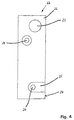
- Fig. 4
- eine Seitenansicht einer die Gelenkkonsole der Fig. 3 bildenden Lasche;
- Fig. 5
- in einer der Fig. 1 entsprechenden, teilweise gebrochenen Seitenansicht ein zweites Ausführungsbeispiel einer Hubladebühne in ihrer abgesenkten unteren Stellung mit vollständiger Ansicht eines Tragarms und eines Hubzylinders;
- Fig. 6
- eine der Fig. 3 entsprechende Schnittansicht durch eine Gelenkkonsole der Hubladebühne in Fig. 5; und
- Fig. 7
- eine Seitenansicht einer die Gelenkkonsole der Fig. 6 bildenden Lasche.
Claims (10)
- Gelenkvorrichtung für eine Hubladebühne eines Fahrzeugs, wobei die Gelenkvorrichtung mindestens eine, vorzugsweise zwei Gelenkkonsolen (5; 30) aufweist, in denen jeweils ein eine keilförmige Plattform tragender Tragarm (1) und ein Hubzylinder (2) schwenkbar gelagert sind, wobei andernends der Tragarm (1) mit dem Hubzylinder (2) gelenkig verbunden ist und die keilförmige Plattform trägt, und wobei die mindestens eine Gelenkkonsole (5; 30) jeweils an Tragelementen (9, 11, 12; 32, 33) schwenkbar gelagert ist,
dadurch gekennzeichnet,
daß jede Gelenkkonsole (5; 30) zwei nebeneinander angeordnete Laschen (6a, 6b; 31a, 31b) aufweist, die jeweils an mindestens einem Tragelement (9, 11, 12; 32, 33) zueinander koaxial gelagert sind, und daß an den beiden Laschen (6a, 6b; 31a, 31b) der Tragarm (1) und der Hubzylinder (2), welche jeweils in den Innenraum (13; 36) zwischen den beiden Laschen (6a, 6b; 31a, 31b) eingreifen, gelagert sind. - Gelenkvorrichtung nach Anspruch 1, dadurch gekennzeichnet, daß die beiden Laschen (6a, 6b) unabhängig voneinander an ihrem jeweiligen Tragelement (9, 11, 12) gelagert sind.
- Gelenkvorrichtung nach Anspruch 2, dadurch gekennzeichnet, daß die beiden Laschen (6a, 6b) jeweils über fliegende Bolzen (8a, 8b), die von dem mindestens einen Tragelement (9, 11, 12) seitlich vorstehen, gelagert sind.
- Gelenkvorrichtung nach einem der Ansprüche 1 bis 3, dadurch gekennzeichnet, daß sich die Drehachse (8', 8'') der Gelenkkonsole (5) oberhalb sowohl der Drehachse (14') des Tragarms (1) als auch der Drehachse (15') des Hubzylinders (2) befindet.
- Gelenkvorrichtung nach einem der Ansprüche 1 bis 3, dadurch gekennzeichnet, daß sich die Drehachse (35') der Gelenkkonsole (30) zwischen der Drehachse (37') des Tragarms (1) und der Drehachse (38') des Hubzylinders (2) befindet.
- Gelenkvorrichtung nach Anspruch 5, dadurch gekennzeichnet, daß die beiden Laschen (31a, 31b) über eine gemeinsame Gelenkverbindung, insbesondere über einen gemeinsamen Lagerbolzen (35), an ihrem jeweiligen Tragelement (32, 33) gelagert sind.
- Gelenkvorrichtung nach einem der vorhergehenden Ansprüche, dadurch gekennzeichnet, daß die Drehachse (14'; 37') des Tragarms (1) und/oder die Drehachse (15', 38') des Hubzylinders (2) über einen Lagerbolzen (14; 37 bzw. 15; 38) gebildet ist.
- Gelenkvorrichtung nach Anspruch 7, dadurch gekennzeichnet, daß der Lagerbolzen (14; 37) des Tragarms (1) und/oder der Lagerbolzen (15; 38) des Hubzylinders (2) in Lageröffnungen (19) bzw. (20; 41) versenkt gelagert sind.
- Gelenkvorrichtung nach Anspruch 7 oder 8, dadurch gekennzeichnet, daß die Innenseiten (26; 44) der beiden Laschen (6a, 6b; 31a, 31b) im Bereich der Lagerung des Lagerbolzens (15; 38) des Hubzylinders (2) für eine Entnahme des Lagerbolzens (15; 38) aus der Gelenkkonsole (5; 30) ausgespart sind.
- Gelenkvorrichtung nach einem der vorhergehenden Ansprüche, dadurch gekennzeichnet, daß im nicht-verschwenkten Zustand die beiden Laschen (6a, 6b; 31a, 31b) an einem Tragprofil (7; 34) der Hubladebühne anliegen.3
Applications Claiming Priority (2)
| Application Number | Priority Date | Filing Date | Title |
|---|---|---|---|
| DE19719830 | 1997-05-13 | ||
| DE19719830A DE19719830A1 (de) | 1997-05-13 | 1997-05-13 | Gelenkvorrichtung für eine Hubladebühne |
Publications (3)
| Publication Number | Publication Date |
|---|---|
| EP0878349A2 true EP0878349A2 (de) | 1998-11-18 |
| EP0878349A3 EP0878349A3 (de) | 1999-04-14 |
| EP0878349B1 EP0878349B1 (de) | 2003-05-02 |
Family
ID=7829221
Family Applications (1)
| Application Number | Title | Priority Date | Filing Date |
|---|---|---|---|
| EP98108200A Expired - Lifetime EP0878349B1 (de) | 1997-05-13 | 1998-05-06 | Gelenkvorrichtung für eine Hubladebühne |
Country Status (3)
| Country | Link |
|---|---|
| EP (1) | EP0878349B1 (de) |
| DE (2) | DE19719830A1 (de) |
| PL (1) | PL191921B1 (de) |
Cited By (3)
| Publication number | Priority date | Publication date | Assignee | Title |
|---|---|---|---|---|
| EP1020324A1 (de) * | 1999-01-15 | 2000-07-19 | Jan Jozef Prudence Dhollander | Verbesserte Hubladebühne für Transportfahrzeug |
| WO2001054942A1 (de) * | 2000-01-26 | 2001-08-02 | Maier Peter Leichtbau Gmbh | Ladebordwand |
| EP1188614A1 (de) * | 2000-09-14 | 2002-03-20 | Dautel Gmbh | Hubladebühnenvorrichtung, insbesondere für Fahrzeuge |
Families Citing this family (1)
| Publication number | Priority date | Publication date | Assignee | Title |
|---|---|---|---|---|
| DE102007058908B3 (de) * | 2007-11-30 | 2009-06-04 | Gerd Bär GmbH | Hubladebühne mit verstellbarem Hubwerk für ein Wasserfahrzeug |
Citations (1)
| Publication number | Priority date | Publication date | Assignee | Title |
|---|---|---|---|---|
| DE3129789C2 (de) | 1981-07-29 | 1991-02-14 | Gerd 7100 Heilbronn De Baer |
Family Cites Families (7)
| Publication number | Priority date | Publication date | Assignee | Title |
|---|---|---|---|---|
| DE1580379A1 (de) * | 1966-03-11 | 1970-12-17 | Meiller Fahrzeuge | Ladevorrichtung,insbesondere fuer Fahrzeuge |
| US3602381A (en) * | 1969-10-27 | 1971-08-31 | Daybrook Ottawa Corp | Load-lifting tailgate |
| DE2352991C3 (de) * | 1972-11-01 | 1985-08-29 | Messerschmitt-Bölkow-Blohm GmbH, 8012 Ottobrunn | Heb- und senkbare sowie hochschwenkbare Plattform |
| DE2654286A1 (de) * | 1976-11-30 | 1978-06-01 | Dautel Emil Kipperbau | Ladevorrichtung fuer lastfahrzeugaufbauten |
| EP0089941A3 (de) * | 1982-03-18 | 1983-11-02 | Karel Marie Caluwaerts | Hydraulische Ladeplattform für Lastwagen und dergleichen |
| DE3544406A1 (de) * | 1985-12-16 | 1987-06-19 | Soerensen Hydraulik Gmbh | Faltbare ladebordwand fuer kraftfahrzeuge |
| DE19613766A1 (de) * | 1996-04-04 | 1997-10-09 | Dautel Emil Gmbh | Hubladebühne |
-
1997
- 1997-05-13 DE DE19719830A patent/DE19719830A1/de not_active Withdrawn
-
1998
- 1998-05-06 DE DE59808122T patent/DE59808122D1/de not_active Expired - Lifetime
- 1998-05-06 EP EP98108200A patent/EP0878349B1/de not_active Expired - Lifetime
- 1998-05-12 PL PL326244A patent/PL191921B1/pl not_active IP Right Cessation
Patent Citations (1)
| Publication number | Priority date | Publication date | Assignee | Title |
|---|---|---|---|---|
| DE3129789C2 (de) | 1981-07-29 | 1991-02-14 | Gerd 7100 Heilbronn De Baer |
Cited By (4)
| Publication number | Priority date | Publication date | Assignee | Title |
|---|---|---|---|---|
| EP1020324A1 (de) * | 1999-01-15 | 2000-07-19 | Jan Jozef Prudence Dhollander | Verbesserte Hubladebühne für Transportfahrzeug |
| BE1012389A3 (nl) * | 1999-01-15 | 2000-10-03 | Jan Jozef Prudence Dhollander | Verbeteringen aan laadkleppen voor vrachtwagens. |
| WO2001054942A1 (de) * | 2000-01-26 | 2001-08-02 | Maier Peter Leichtbau Gmbh | Ladebordwand |
| EP1188614A1 (de) * | 2000-09-14 | 2002-03-20 | Dautel Gmbh | Hubladebühnenvorrichtung, insbesondere für Fahrzeuge |
Also Published As
| Publication number | Publication date |
|---|---|
| DE59808122D1 (de) | 2003-06-05 |
| EP0878349A3 (de) | 1999-04-14 |
| PL326244A1 (en) | 1998-11-23 |
| EP0878349B1 (de) | 2003-05-02 |
| DE19719830A1 (de) | 1998-11-19 |
| PL191921B1 (pl) | 2006-07-31 |
Similar Documents
| Publication | Publication Date | Title |
|---|---|---|
| DE69835109T2 (de) | Hebegerät mit einem Gelenkausleger in Form eines Doppeparallelogramms | |
| DE3015685A1 (de) | Lastenheber fuer paletten | |
| EP1902933A2 (de) | Achslift für luftgefederte Fahrzeugachsen | |
| DE69207817T2 (de) | Hebevorrichtung mit vertikaler Verlagerung einer Ladetragebene | |
| DE68920505T2 (de) | Drehkipper für Eisenbahnwaggons. | |
| DE1580662B2 (de) | Unterhalb einer ladeflaeche, insbesondere eines fahrzeuges, verstaubare ladebuehne | |
| DE1680107C3 (de) | Vorrichtung für Fahrzeuge zum Auf- und Abladen von Lasten | |
| DE3147602C2 (de) | ||
| EP0664767B1 (de) | Flachbauende hebebühne | |
| DE2406342A1 (de) | Scherenrahmen, insbesondere fuer kippfahrzeuge | |
| DE1481201C3 (de) | Hebevorrichtung zum Umsetzen von Lasten | |
| DE2705979C3 (de) | Lastwagen mit in seiner Längsrichtung verschiebbarem Ladebodenabschnitt | |
| DE2758852A1 (de) | Ladeeinrichtung | |
| EP0878349B1 (de) | Gelenkvorrichtung für eine Hubladebühne | |
| DE1506519C2 (de) | Teleskopausleger | |
| EP0502469A1 (de) | Unterfahrschutz für Nutzfahrzeuge | |
| DE3737651A1 (de) | Vorrichtung fuer eine unterfalt-ladebordwand | |
| DE2755986C2 (de) | Wippwerk für einen Kran | |
| DE2714276B2 (de) | Schaufellader | |
| DE10361322A1 (de) | Zur Wartung von Fahrzeugen verwendete Hebebühne | |
| EP0830976A2 (de) | Fahrzeugtransporter | |
| EP2604472A1 (de) | Hubladebühne | |
| DE2325513C2 (de) | Garage zum Abstellen zweier Fahrzeuge übereinander | |
| DE3409405A1 (de) | Transportfahrzeug | |
| DE2324555B2 (de) | Vorrichtung zum kippen eines wagenkastens |
Legal Events
| Date | Code | Title | Description |
|---|---|---|---|
| PUAI | Public reference made under article 153(3) epc to a published international application that has entered the european phase |
Free format text: ORIGINAL CODE: 0009012 |
|
| AK | Designated contracting states |
Kind code of ref document: A2 Designated state(s): DE FR GB |
|
| AX | Request for extension of the european patent |
Free format text: AL;LT;LV;MK;RO;SI |
|
| PUAL | Search report despatched |
Free format text: ORIGINAL CODE: 0009013 |
|
| AK | Designated contracting states |
Kind code of ref document: A3 Designated state(s): AT BE CH CY DE DK ES FI FR GB GR IE IT LI LU MC NL PT SE |
|
| AX | Request for extension of the european patent |
Free format text: AL;LT;LV;MK;RO;SI |
|
| 17P | Request for examination filed |
Effective date: 19991013 |
|
| AKX | Designation fees paid |
Free format text: DE FR GB |
|
| 17Q | First examination report despatched |
Effective date: 20011221 |
|
| GRAH | Despatch of communication of intention to grant a patent |
Free format text: ORIGINAL CODE: EPIDOS IGRA |
|
| GRAH | Despatch of communication of intention to grant a patent |
Free format text: ORIGINAL CODE: EPIDOS IGRA |
|
| GRAA | (expected) grant |
Free format text: ORIGINAL CODE: 0009210 |
|
| AK | Designated contracting states |
Designated state(s): DE FR GB |
|
| REG | Reference to a national code |
Ref country code: GB Ref legal event code: FG4D Free format text: NOT ENGLISH |
|
| GBT | Gb: translation of ep patent filed (gb section 77(6)(a)/1977) |
Effective date: 20030502 |
|
| REF | Corresponds to: |
Ref document number: 59808122 Country of ref document: DE Date of ref document: 20030605 Kind code of ref document: P |
|
| ET | Fr: translation filed | ||
| PLBE | No opposition filed within time limit |
Free format text: ORIGINAL CODE: 0009261 |
|
| STAA | Information on the status of an ep patent application or granted ep patent |
Free format text: STATUS: NO OPPOSITION FILED WITHIN TIME LIMIT |
|
| 26N | No opposition filed |
Effective date: 20040203 |
|
| PGFP | Annual fee paid to national office [announced via postgrant information from national office to epo] |
Ref country code: GB Payment date: 20080410 Year of fee payment: 11 |
|
| GBPC | Gb: european patent ceased through non-payment of renewal fee |
Effective date: 20090506 |
|
| PG25 | Lapsed in a contracting state [announced via postgrant information from national office to epo] |
Ref country code: GB Free format text: LAPSE BECAUSE OF NON-PAYMENT OF DUE FEES Effective date: 20090506 |
|
| REG | Reference to a national code |
Ref country code: FR Ref legal event code: PLFP Year of fee payment: 19 |
|
| REG | Reference to a national code |
Ref country code: FR Ref legal event code: PLFP Year of fee payment: 20 |
|
| PGFP | Annual fee paid to national office [announced via postgrant information from national office to epo] |
Ref country code: FR Payment date: 20170522 Year of fee payment: 20 |
|
| PGFP | Annual fee paid to national office [announced via postgrant information from national office to epo] |
Ref country code: DE Payment date: 20170721 Year of fee payment: 20 |
|
| REG | Reference to a national code |
Ref country code: DE Ref legal event code: R071 Ref document number: 59808122 Country of ref document: DE |