EP0880877A1 - Method of spreading flowable material, apparatus for use in carrying out the method, and spreader vane for use in the apparatus - Google Patents
Method of spreading flowable material, apparatus for use in carrying out the method, and spreader vane for use in the apparatus Download PDFInfo
- Publication number
- EP0880877A1 EP0880877A1 EP98100192A EP98100192A EP0880877A1 EP 0880877 A1 EP0880877 A1 EP 0880877A1 EP 98100192 A EP98100192 A EP 98100192A EP 98100192 A EP98100192 A EP 98100192A EP 0880877 A1 EP0880877 A1 EP 0880877A1
- Authority
- EP
- European Patent Office
- Prior art keywords
- spreader
- disk
- radially inner
- flowable material
- sense
- Prior art date
- Legal status (The legal status is an assumption and is not a legal conclusion. Google has not performed a legal analysis and makes no representation as to the accuracy of the status listed.)
- Granted
Links
- 239000000463 material Substances 0.000 title claims abstract description 31
- 230000009969 flowable effect Effects 0.000 title claims description 14
- 238000000034 method Methods 0.000 title claims description 11
- 230000000903 blocking effect Effects 0.000 claims description 5
- 230000002093 peripheral effect Effects 0.000 claims 1
- 210000003608 fece Anatomy 0.000 abstract description 4
- 239000010871 livestock manure Substances 0.000 abstract description 4
- 238000010276 construction Methods 0.000 description 3
- 230000000694 effects Effects 0.000 description 2
- 239000008187 granular material Substances 0.000 description 1
Images


Classifications
-
- A—HUMAN NECESSITIES
- A01—AGRICULTURE; FORESTRY; ANIMAL HUSBANDRY; HUNTING; TRAPPING; FISHING
- A01C—PLANTING; SOWING; FERTILISING
- A01C17/00—Fertilisers or seeders with centrifugal wheels
- A01C17/006—Regulating or dosing devices
- A01C17/008—Devices controlling the quantity or the distribution pattern
-
- A—HUMAN NECESSITIES
- A01—AGRICULTURE; FORESTRY; ANIMAL HUSBANDRY; HUNTING; TRAPPING; FISHING
- A01C—PLANTING; SOWING; FERTILISING
- A01C17/00—Fertilisers or seeders with centrifugal wheels
- A01C17/001—Centrifugal throwing devices with a vertical axis
Definitions
- the present invention relates to a method of spreading flowable material, such as set forth in more detail in the preamble of claim 1.
- a method of this kind is disclosed in the Danish patent application No. 1122/96 (B, S & Co. ref. 56339).
- the spreading pattern can be changed, e.g. with a view to be able to pass along a field boundary or a watercourse without spreading e.g. manure beyond certain limits, by using a spreading apparatus with two disks and making these disks rotate in the same or opposite sense in different directions, and possibly blocking the supply of spreadable material to one of the disks.
- the present invention also relates to an apparatus for carrying out the method of the invention.
- This apparatus is of the kind set forth in the preamble of claim 3, and according to the invention, this apparatus is characterized by the construction and arrangement set forth in the characterizing clause of this claim 3.
- the present invention relates to a spreader vane for use in the apparatus mentioned above.
- This spreader vane is of the kind set forth in the preamble of claim 8, and according to the invention, this spreader vane is characterized by a construction as set forth in the characterizing clause of this claim 8.
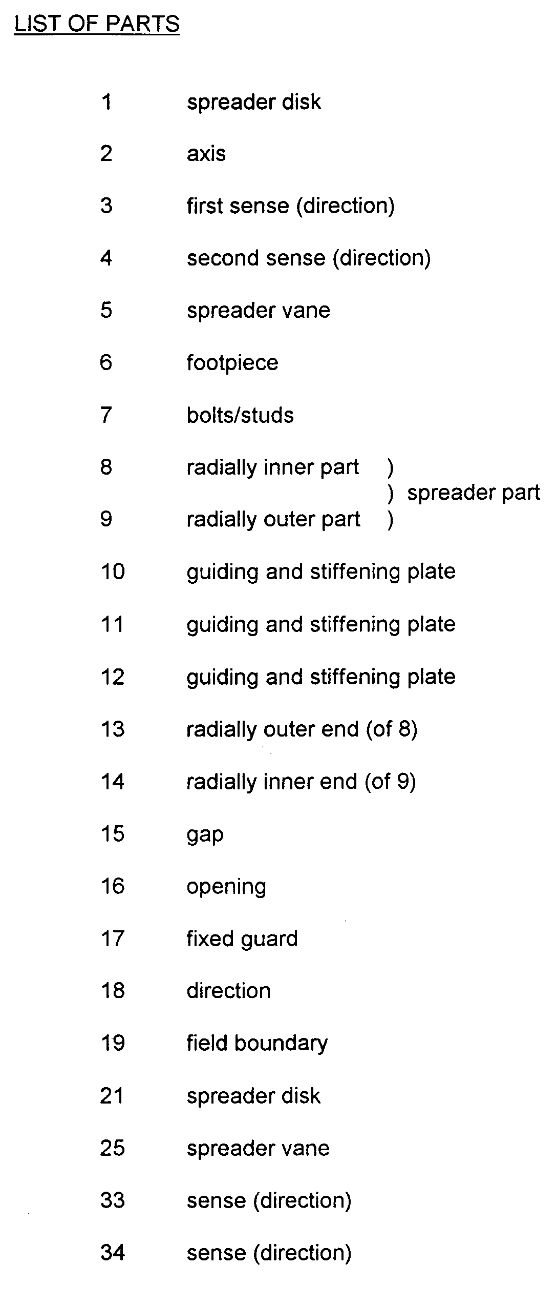
- Figure 1 shows a dish-shaped spreader disk 1 adapted to rotate about an axis 2, being generally vertical during operation, in a first sense 3 or in a second and oppposite sense 4, such as will be explained in more detail below.
- the spreader disk 1 carries two spreader vanes 5, each consisting of
- the special feature of the spreader vanes 5 according to the present invention consists in that the active spreader part 8, 9 is divided into two parts, viz. a radially inner part 8 and a radially outer part 9, and in that the radially outer end 13 of the radially inner part 8 is offset in the radial and tangential directions relative to the radially inner end 14 of the radially outer part 9, so that, cf. also Figures 2 and 3, a gap 15, extending parallel to the axis 2 of rotation, is formed between said ends 13 and 14.
- Figure 4 shows a part of a spreading apparatus according to the present invention, in which at least the spreader disk 1 situated to the left carries spreader vanes 5 of the construction described above, whereas the spreader disk 21 situated to the right in the example shown carries spreader vanes 25 of a previously known type.
- a container for flowable material, e.g. manure in the form of granules, likewise in a known manner falling down through suitable openings 16 in the bottom of said container, as mentioned otherwise not shown.
- flowable material e.g. manure in the form of granules
- the material is thrown outwards by the centrifugal force, presumably assisted by the air current created by the spreader vanes 5 and 25, until it is intercepted by the vanes and thrown further outwardly from the disks 1 and 21 in spreading patterns as indicated in Figure 5, the forwardmost limit of which is determined by fixed guards 17, while the limits to the sides and the rear are determined by the throwing distance, the latter again depending on inter alia at which velocity the material leaves the spreader vanes 5 and 25.
- Figure 6 shows such a situation, in which the material must not be spread beyond a symbolically indicated field boundary 19.
- the supply to the spreader disk 21 is blocked, and the spreader disks are made to rotate in the opposite senses 4 and 34, respectively, i.e. oppositely to the normal rotational senses 3 and 33.
- the material this time symbolized by "filled” circles ⁇ , will “fall down” from the radially inner part 8 through the gap 15, and thus receive considerably less kinetic energy - i.e. be given a considerably lower velocity - than in the operational state shown in Figure 5.
- This results in part in a decrease in the throwing distance in part in that the fixed guide 17 associated with the disk 1 causes a cutting-off of the spreading pattern at its rear end, so that this pattern is kept clear of the field boundary 19.
- the spreader disk 21 situated to the right is equipped with spreader vanes 25 of a previously known type, i.e. without the gap 15, but it lies within the scope of the present invention to provide even this disk 21 with spreader vanes 5 according to the invention.
- the manually operated cable or rod connections may be common to the means determining the rotational sense of the spreader disks and the means blocking one or the other of the outlet openings 16, all in such a manner, that when a spreader disk rotates "backwards", i.e. in the sense 4 or 34, the outlet opening 16 associated with the control means will be blocked.
- adjustable screens or guides e.g. of the type known from EP-A2-0.699.377, and let the common remote-control means act upon these screens or guides as well, all in such a manner that a limiting screen or guide will stop material not having been caught by the fixed guides 17. The effect of this is that "stray" material will not be thrown out across the field boundary 19, but will instead hit the screen or guide and fall vertically downwards.
Landscapes
- Life Sciences & Earth Sciences (AREA)
- Soil Sciences (AREA)
- Environmental Sciences (AREA)
- Fertilizing (AREA)
Abstract
Description
- a
footpiece 6, in a known manner adjustably secured to and co-planar with the disk 1 by means of - bolts or
studs 7, - an
active spreader part - guiding and
stiffening plates
Claims (8)
- Method of spreading flowable material using at least one spreader disk on its upper side provided with at least one generally radially extending spreader vane, said spreader disk rotating in either a first or a second, opposite sense or direction about a generally vertical axis and receiving the flowable material from above, throwing said material out beyond its peripheral edge by means of said spreader vane or vanes, characterized by the use of at least one spreader vane so adapted that when the spreader disk rotates in said first sense or direction, its engagement with the flowable material ceases at a first radial distance from the rotational axis of the spreader disk, while when the spreader disk rotates in said second, opposite sense or direction, its engagement with the flowable material ceases at a second radial distance from the rotational axis of the spreader disk, said second distance being different from said first distance.
- Method according to claim 1 and with the use of one or a number of spreader vanes, each comprising a base part, with which it is secured, possibly adjustably, to a spreader disk, and a spreader part protruding upwardly from the base part and having a not inconsiderable extent in the axial and radial directions, characterized by the use of at least one spreader vane, in which the spreader part comprises a radially inner part and a radially outer part, the radially outer end of the radially inner part being offset in such a manner in the radial and tangential direction relative to the radially inner end of the radially outer part, that between them there is formed an opening, through which the flowable material can pass.
- Apparatus for carrying out the method according to claim 1 or 2 by spreading flowable material and comprisinga) at least one container for flowable material and comprising at least one outlet opening (16) for the material,b) situated below at least one of said outlet openings (16) a spreader disk (1) adapted to rotate about a generally vertical axis (2) in either a first sense or direction or in a second, opposite sense or direction, andc) at least one spreader vane (5) secured to the upper side of each spreader disk and comprisingc1) a base part (6), by which it is secured, possibly adjustably, to the spreader disk, andc2) a spreader part (8,9) protruding upwardly from the base part (6) and having a not inconsiderable extent in the axial and radial directions,
characterized ind) that at least one spreader vane (5) comprises a spreader part (8,9) having a radially inner part (8) and a radially outer part (9), the radially outer end (13) of the radially inner part (8) being offset in such a manner in the radial and tangential direction relative to the radially inner end (14) of the radially outer part (9), that between them there is formed an opening (15), through which the flowable material can pass. - Apparatus according to claim 3, characterized in that said radially inner (8) and outer (9) parts are mutually offset in the tangential direction to such a degree that when the spreader disk rotates in a sense or direction, in which the radially inner part (8) is forwardmost, no more than an insignificant proportion of the flowable material will come into contact with the radially outer part (9).
- Apparatus according to claim 3 or 4, characterized by means for selectively blocking at least one outlet opening (16).
- Apparatus according to claim 5, characterized by common remote-control means to act upon the rotational sense or direction of the spreader disk or disks (1,21) and the means for blocking the outlet opening or openings (16) in such a manner, that when the rotational sense of a spreader disk is such that the radially inner spreader part (8) is rearwardmost, then the associated outlet opening (16) will be blocked.
- Apparatus according to claim 6 and of the kind comprising at least one limiting screen or guard movable between an active position, in which it constitutes an obstruction for at least a part of the material being thrown out from a spreader disk, and a passive position, in which it does not constitute such an obstruction, characterized in that the common remote-control means are also adapted to move the limiting screen or screens or guard or guards between said two positions in such a manner, that when the rotational sense or direction of the associated spreader disk is that mentioned in claim 6, then the associated limting screen or guard will be in said active position.
- Spreader vane (5) for use in an apparatus according to any one or any of the claims 3-7 and of the kind comprisinga) a base part (6), by which it can be secured to a spreader disk (1,21) in the apparatus, andb) a spreader part (8,9) protruding upward from the base part (6) during operation and having a not inconsiderable extent in the axial and tangential directions,
characterized inc) that the spreader part (8,9) comprises a radially inner part (8) and a radially outer part (9), the radially outer end (13) of the radially inner part (8) being offset in such a manner in the radial and tangential direction relative to the radially inner end (14) of the radially outer part (9), that between them there is formed an opening (15), through which the flowable material can pass.
Applications Claiming Priority (2)
| Application Number | Priority Date | Filing Date | Title |
|---|---|---|---|
| DK48297 | 1997-04-30 | ||
| DK48297A DK172715B1 (en) | 1997-04-30 | 1997-04-30 | Method of spreading rice-resistant material, apparatus for use in the practice of the method, and spreading wing ten |
Publications (2)
| Publication Number | Publication Date |
|---|---|
| EP0880877A1 true EP0880877A1 (en) | 1998-12-02 |
| EP0880877B1 EP0880877B1 (en) | 2002-05-22 |
Family
ID=8094059
Family Applications (1)
| Application Number | Title | Priority Date | Filing Date |
|---|---|---|---|
| EP19980100192 Expired - Lifetime EP0880877B1 (en) | 1997-04-30 | 1998-01-08 | Method of spreading flowable material, apparatus for use in carrying out the method, and spreader vane for use in the apparatus |
Country Status (3)
| Country | Link |
|---|---|
| EP (1) | EP0880877B1 (en) |
| DE (1) | DE69805467T2 (en) |
| DK (2) | DK172715B1 (en) |
Cited By (9)
| Publication number | Priority date | Publication date | Assignee | Title |
|---|---|---|---|---|
| EP0981939A1 (en) * | 1998-08-26 | 2000-03-01 | A.P. Laursen A/S | Method of spreading flowable material |
| EP1031268A1 (en) * | 1999-02-26 | 2000-08-30 | Amazonen-Werke H. Dreyer GmbH & Co. KG | Centrifugal fertiliser spreader |
| EP1090542A3 (en) * | 1999-10-09 | 2001-09-26 | Amazonen-Werke H. Dreyer GmbH & Co. KG | Centrifugal spreader |
| EP1183922A3 (en) * | 2000-08-31 | 2002-07-03 | Amazonen-Werke H. Dreyer GmbH & Co. KG | Centrifugal fertilizer spreader |
| EP1238578A2 (en) | 2001-03-10 | 2002-09-11 | Rauch Landmaschinenfabrik Gmbh | Method for distribution of scattering material and centrifugal distributer for carrying out the method |
| EP1247437A2 (en) | 2001-04-05 | 2002-10-09 | Rauch Landmaschinenfabrik Gmbh | Method for distributing granular material and centrifugal distributer for carrying out this method |
| EP1269817A2 (en) | 2001-06-18 | 2003-01-02 | Rauch Landmaschinenfabrik Gmbh | Method and centrifugal distributer for distribution of scattering material |
| ITAL20110010A1 (en) * | 2011-11-09 | 2013-05-10 | Cosmo S R L | DEVICE FOR THE DISTRIBUTION OF POWDERED OR GRANULAR MATERIALS, SUCH AS FERTILIZERS, SALT OR SIMILAR, WITH REVERSIBLE OPERATING DISC PALETTE PALLETS, FOR SPREADER, SIMILAR OR SIMILAR EQUIPMENT. |
| ES2442955A1 (en) * | 2012-08-14 | 2014-02-14 | Aitor BRUN GARCÍA | Grain material distribution machine (Machine-translation by Google Translate, not legally binding) |
Families Citing this family (1)
| Publication number | Priority date | Publication date | Assignee | Title |
|---|---|---|---|---|
| PL71190Y1 (en) * | 2017-11-09 | 2020-01-31 | Worek Jerzy Przed Produkcyjno Uslugowo Handlowe Woprol | The spreading vane of the discharge disc for a centrifugal fertilizer spreader |
Citations (4)
| Publication number | Priority date | Publication date | Assignee | Title |
|---|---|---|---|---|
| FR2496390A1 (en) * | 1980-12-24 | 1982-06-25 | Amazonen Werke Dreyer H | CENTRIFUGAL DISPENSER, IN PARTICULAR FOR THE SPREADING OF FERTILIZERS |
| EP0192085A1 (en) * | 1985-02-16 | 1986-08-27 | ACCORD Landmaschinen Heinrich Weiste & Co. GmbH | Two disc fertilizer spreader |
| DE3812087A1 (en) * | 1988-04-12 | 1989-10-26 | Amazonen Werke Dreyer H | SLINGER |
| EP0699377A2 (en) | 1994-09-03 | 1996-03-06 | Amazonen-Werke H. Dreyer GmbH & Co. KG | Broadcaster |
-
1997
- 1997-04-30 DK DK48297A patent/DK172715B1/en not_active IP Right Cessation
-
1998
- 1998-01-08 DE DE1998605467 patent/DE69805467T2/en not_active Expired - Fee Related
- 1998-01-08 DK DK98100192T patent/DK0880877T3/en active
- 1998-01-08 EP EP19980100192 patent/EP0880877B1/en not_active Expired - Lifetime
Patent Citations (4)
| Publication number | Priority date | Publication date | Assignee | Title |
|---|---|---|---|---|
| FR2496390A1 (en) * | 1980-12-24 | 1982-06-25 | Amazonen Werke Dreyer H | CENTRIFUGAL DISPENSER, IN PARTICULAR FOR THE SPREADING OF FERTILIZERS |
| EP0192085A1 (en) * | 1985-02-16 | 1986-08-27 | ACCORD Landmaschinen Heinrich Weiste & Co. GmbH | Two disc fertilizer spreader |
| DE3812087A1 (en) * | 1988-04-12 | 1989-10-26 | Amazonen Werke Dreyer H | SLINGER |
| EP0699377A2 (en) | 1994-09-03 | 1996-03-06 | Amazonen-Werke H. Dreyer GmbH & Co. KG | Broadcaster |
Cited By (9)
| Publication number | Priority date | Publication date | Assignee | Title |
|---|---|---|---|---|
| EP0981939A1 (en) * | 1998-08-26 | 2000-03-01 | A.P. Laursen A/S | Method of spreading flowable material |
| EP1031268A1 (en) * | 1999-02-26 | 2000-08-30 | Amazonen-Werke H. Dreyer GmbH & Co. KG | Centrifugal fertiliser spreader |
| EP1090542A3 (en) * | 1999-10-09 | 2001-09-26 | Amazonen-Werke H. Dreyer GmbH & Co. KG | Centrifugal spreader |
| EP1183922A3 (en) * | 2000-08-31 | 2002-07-03 | Amazonen-Werke H. Dreyer GmbH & Co. KG | Centrifugal fertilizer spreader |
| EP1238578A2 (en) | 2001-03-10 | 2002-09-11 | Rauch Landmaschinenfabrik Gmbh | Method for distribution of scattering material and centrifugal distributer for carrying out the method |
| EP1247437A2 (en) | 2001-04-05 | 2002-10-09 | Rauch Landmaschinenfabrik Gmbh | Method for distributing granular material and centrifugal distributer for carrying out this method |
| EP1269817A2 (en) | 2001-06-18 | 2003-01-02 | Rauch Landmaschinenfabrik Gmbh | Method and centrifugal distributer for distribution of scattering material |
| ITAL20110010A1 (en) * | 2011-11-09 | 2013-05-10 | Cosmo S R L | DEVICE FOR THE DISTRIBUTION OF POWDERED OR GRANULAR MATERIALS, SUCH AS FERTILIZERS, SALT OR SIMILAR, WITH REVERSIBLE OPERATING DISC PALETTE PALLETS, FOR SPREADER, SIMILAR OR SIMILAR EQUIPMENT. |
| ES2442955A1 (en) * | 2012-08-14 | 2014-02-14 | Aitor BRUN GARCÍA | Grain material distribution machine (Machine-translation by Google Translate, not legally binding) |
Also Published As
| Publication number | Publication date |
|---|---|
| DE69805467D1 (en) | 2002-06-27 |
| DE69805467T2 (en) | 2002-11-07 |
| DK172715B1 (en) | 1999-06-14 |
| DK0880877T3 (en) | 2002-08-19 |
| EP0880877B1 (en) | 2002-05-22 |
| DK48297A (en) | 1998-10-31 |
Similar Documents
| Publication | Publication Date | Title |
|---|---|---|
| EP0880877B1 (en) | Method of spreading flowable material, apparatus for use in carrying out the method, and spreader vane for use in the apparatus | |
| US9538701B2 (en) | Method for controlling a device for changing the spreading ring sector of a disc spreader and disc spreader designed to carry out such a method | |
| DE69911063T2 (en) | STABILIZING DEVICE FOR A ROBOTIC OR REMOTE CONTROLLED FLYING PLATFORM | |
| JP7461507B2 (en) | A lawnmower equipped with a partition plate for dividing an enclosed space into an upper space and a cutting space. | |
| US4681265A (en) | Swath-controlling variable chute and chute-activated damper for a broadcast spreader | |
| GB1604894A (en) | Mowing machine | |
| US4738403A (en) | Wheel for a vacuum projection grinder | |
| DE69510998T2 (en) | Process to regulate the spreading width for a granule spreader | |
| US3478970A (en) | Manure spreaders | |
| US3756517A (en) | Forage blower with recutter | |
| USRE32382E (en) | Digging wheel for a suction dredger vessel | |
| EP0490208B1 (en) | Spinnerdisc for Winterservice-Spreading-Apparatus | |
| EP0080239A2 (en) | Device for spreading granular and/or powdery material | |
| US6176280B1 (en) | Disc saw felling head chip path management construction | |
| US4691504A (en) | Rotary mower for a tractor | |
| EP0075549B1 (en) | Apparatus for spreading granular material | |
| US4316581A (en) | Spreader suitable for spreading granular and/or powdery material | |
| EP0117005A2 (en) | A spreader | |
| EP1145614B1 (en) | Apparatus for distributing particulate fertilizer | |
| WO1991005460A1 (en) | Discharging apparatus | |
| US3315810A (en) | Centrifuge having frusto-conical screen with means to improve screen life | |
| EP1208733A1 (en) | An apparatus for spreading flowable material | |
| US4462550A (en) | Apparatus for distributing a substance | |
| CN119572294B (en) | Vortex dust control device | |
| EP0876747A1 (en) | An implement for spreading granular and/or pulverulent material |
Legal Events
| Date | Code | Title | Description |
|---|---|---|---|
| PUAI | Public reference made under article 153(3) epc to a published international application that has entered the european phase |
Free format text: ORIGINAL CODE: 0009012 |
|
| AK | Designated contracting states |
Kind code of ref document: A1 Designated state(s): DE DK FR GB NL |
|
| AX | Request for extension of the european patent |
Free format text: AL;LT;LV;RO;SI |
|
| 17P | Request for examination filed |
Effective date: 19990602 |
|
| AKX | Designation fees paid |
Free format text: DE DK FR GB NL |
|
| GRAG | Despatch of communication of intention to grant |
Free format text: ORIGINAL CODE: EPIDOS AGRA |
|
| 17Q | First examination report despatched |
Effective date: 20011011 |
|
| GRAG | Despatch of communication of intention to grant |
Free format text: ORIGINAL CODE: EPIDOS AGRA |
|
| GRAH | Despatch of communication of intention to grant a patent |
Free format text: ORIGINAL CODE: EPIDOS IGRA |
|
| GRAH | Despatch of communication of intention to grant a patent |
Free format text: ORIGINAL CODE: EPIDOS IGRA |
|
| GRAA | (expected) grant |
Free format text: ORIGINAL CODE: 0009210 |
|
| REG | Reference to a national code |
Ref country code: GB Ref legal event code: FG4D |
|
| REF | Corresponds to: |
Ref document number: 69805467 Country of ref document: DE Date of ref document: 20020627 |
|
| REG | Reference to a national code |
Ref country code: DK Ref legal event code: T3 |
|
| ET | Fr: translation filed | ||
| PGFP | Annual fee paid to national office [announced via postgrant information from national office to epo] |
Ref country code: GB Payment date: 20021223 Year of fee payment: 6 |
|
| PLBE | No opposition filed within time limit |
Free format text: ORIGINAL CODE: 0009261 |
|
| STAA | Information on the status of an ep patent application or granted ep patent |
Free format text: STATUS: NO OPPOSITION FILED WITHIN TIME LIMIT |
|
| 26N | No opposition filed |
Effective date: 20030225 |
|
| PG25 | Lapsed in a contracting state [announced via postgrant information from national office to epo] |
Ref country code: GB Free format text: LAPSE BECAUSE OF NON-PAYMENT OF DUE FEES Effective date: 20040108 |
|
| GBPC | Gb: european patent ceased through non-payment of renewal fee |
Effective date: 20040108 |
|
| PGFP | Annual fee paid to national office [announced via postgrant information from national office to epo] |
Ref country code: DK Payment date: 20090128 Year of fee payment: 12 |
|
| PGFP | Annual fee paid to national office [announced via postgrant information from national office to epo] |
Ref country code: NL Payment date: 20081231 Year of fee payment: 12 Ref country code: DE Payment date: 20090131 Year of fee payment: 12 |
|
| PGFP | Annual fee paid to national office [announced via postgrant information from national office to epo] |
Ref country code: FR Payment date: 20081217 Year of fee payment: 12 |
|
| REG | Reference to a national code |
Ref country code: NL Ref legal event code: V1 Effective date: 20100801 |
|
| REG | Reference to a national code |
Ref country code: DK Ref legal event code: EBP |
|
| REG | Reference to a national code |
Ref country code: FR Ref legal event code: ST Effective date: 20100930 |
|
| PG25 | Lapsed in a contracting state [announced via postgrant information from national office to epo] |
Ref country code: NL Free format text: LAPSE BECAUSE OF NON-PAYMENT OF DUE FEES Effective date: 20100801 Ref country code: FR Free format text: LAPSE BECAUSE OF NON-PAYMENT OF DUE FEES Effective date: 20100201 |
|
| PG25 | Lapsed in a contracting state [announced via postgrant information from national office to epo] |
Ref country code: DE Free format text: LAPSE BECAUSE OF NON-PAYMENT OF DUE FEES Effective date: 20100803 |
|
| PG25 | Lapsed in a contracting state [announced via postgrant information from national office to epo] |
Ref country code: DK Free format text: LAPSE BECAUSE OF NON-PAYMENT OF DUE FEES Effective date: 20100131 |