EP0881197A2 - Appareil et procédé de revêtement d'un récipiant en verre ou en plastique au moyen de plasma CVD - Google Patents
Appareil et procédé de revêtement d'un récipiant en verre ou en plastique au moyen de plasma CVD Download PDFInfo
- Publication number
- EP0881197A2 EP0881197A2 EP98106672A EP98106672A EP0881197A2 EP 0881197 A2 EP0881197 A2 EP 0881197A2 EP 98106672 A EP98106672 A EP 98106672A EP 98106672 A EP98106672 A EP 98106672A EP 0881197 A2 EP0881197 A2 EP 0881197A2
- Authority
- EP
- European Patent Office
- Prior art keywords
- container
- plasma
- coating
- hollow body
- gas
- Prior art date
- Legal status (The legal status is an assumption and is not a legal conclusion. Google has not performed a legal analysis and makes no representation as to the accuracy of the status listed.)
- Withdrawn
Links
Images


Classifications
-
- C—CHEMISTRY; METALLURGY
- C03—GLASS; MINERAL OR SLAG WOOL
- C03C—CHEMICAL COMPOSITION OF GLASSES, GLAZES OR VITREOUS ENAMELS; SURFACE TREATMENT OF GLASS; SURFACE TREATMENT OF FIBRES OR FILAMENTS MADE FROM GLASS, MINERALS OR SLAGS; JOINING GLASS TO GLASS OR OTHER MATERIALS
- C03C17/00—Surface treatment of glass, not in the form of fibres or filaments, by coating
- C03C17/001—General methods for coating; Devices therefor
- C03C17/003—General methods for coating; Devices therefor for hollow ware, e.g. containers
- C03C17/005—Coating the outside
-
- B—PERFORMING OPERATIONS; TRANSPORTING
- B05—SPRAYING OR ATOMISING IN GENERAL; APPLYING FLUENT MATERIALS TO SURFACES, IN GENERAL
- B05D—PROCESSES FOR APPLYING FLUENT MATERIALS TO SURFACES, IN GENERAL
- B05D1/00—Processes for applying liquids or other fluent materials
- B05D1/62—Plasma-deposition of organic layers
-
- C—CHEMISTRY; METALLURGY
- C23—COATING METALLIC MATERIAL; COATING MATERIAL WITH METALLIC MATERIAL; CHEMICAL SURFACE TREATMENT; DIFFUSION TREATMENT OF METALLIC MATERIAL; COATING BY VACUUM EVAPORATION, BY SPUTTERING, BY ION IMPLANTATION OR BY CHEMICAL VAPOUR DEPOSITION, IN GENERAL; INHIBITING CORROSION OF METALLIC MATERIAL OR INCRUSTATION IN GENERAL
- C23C—COATING METALLIC MATERIAL; COATING MATERIAL WITH METALLIC MATERIAL; SURFACE TREATMENT OF METALLIC MATERIAL BY DIFFUSION INTO THE SURFACE, BY CHEMICAL CONVERSION OR SUBSTITUTION; COATING BY VACUUM EVAPORATION, BY SPUTTERING, BY ION IMPLANTATION OR BY CHEMICAL VAPOUR DEPOSITION, IN GENERAL
- C23C16/00—Chemical coating by decomposition of gaseous compounds, without leaving reaction products of surface material in the coating, i.e. chemical vapour deposition [CVD] processes
- C23C16/44—Chemical coating by decomposition of gaseous compounds, without leaving reaction products of surface material in the coating, i.e. chemical vapour deposition [CVD] processes characterised by the method of coating
- C23C16/50—Chemical coating by decomposition of gaseous compounds, without leaving reaction products of surface material in the coating, i.e. chemical vapour deposition [CVD] processes characterised by the method of coating using electric discharges
- C23C16/505—Chemical coating by decomposition of gaseous compounds, without leaving reaction products of surface material in the coating, i.e. chemical vapour deposition [CVD] processes characterised by the method of coating using electric discharges using radio frequency discharges
- C23C16/509—Chemical coating by decomposition of gaseous compounds, without leaving reaction products of surface material in the coating, i.e. chemical vapour deposition [CVD] processes characterised by the method of coating using electric discharges using radio frequency discharges using internal electrodes
-
- C—CHEMISTRY; METALLURGY
- C23—COATING METALLIC MATERIAL; COATING MATERIAL WITH METALLIC MATERIAL; CHEMICAL SURFACE TREATMENT; DIFFUSION TREATMENT OF METALLIC MATERIAL; COATING BY VACUUM EVAPORATION, BY SPUTTERING, BY ION IMPLANTATION OR BY CHEMICAL VAPOUR DEPOSITION, IN GENERAL; INHIBITING CORROSION OF METALLIC MATERIAL OR INCRUSTATION IN GENERAL
- C23C—COATING METALLIC MATERIAL; COATING MATERIAL WITH METALLIC MATERIAL; SURFACE TREATMENT OF METALLIC MATERIAL BY DIFFUSION INTO THE SURFACE, BY CHEMICAL CONVERSION OR SUBSTITUTION; COATING BY VACUUM EVAPORATION, BY SPUTTERING, BY ION IMPLANTATION OR BY CHEMICAL VAPOUR DEPOSITION, IN GENERAL
- C23C16/00—Chemical coating by decomposition of gaseous compounds, without leaving reaction products of surface material in the coating, i.e. chemical vapour deposition [CVD] processes
- C23C16/44—Chemical coating by decomposition of gaseous compounds, without leaving reaction products of surface material in the coating, i.e. chemical vapour deposition [CVD] processes characterised by the method of coating
- C23C16/50—Chemical coating by decomposition of gaseous compounds, without leaving reaction products of surface material in the coating, i.e. chemical vapour deposition [CVD] processes characterised by the method of coating using electric discharges
- C23C16/511—Chemical coating by decomposition of gaseous compounds, without leaving reaction products of surface material in the coating, i.e. chemical vapour deposition [CVD] processes characterised by the method of coating using electric discharges using microwave discharges
-
- H—ELECTRICITY
- H01—ELECTRIC ELEMENTS
- H01J—ELECTRIC DISCHARGE TUBES OR DISCHARGE LAMPS
- H01J37/00—Discharge tubes with provision for introducing objects or material to be exposed to the discharge, e.g. for the purpose of examination or processing thereof
- H01J37/32—Gas-filled discharge tubes
- H01J37/32009—Arrangements for generation of plasma specially adapted for examination or treatment of objects, e.g. plasma sources
- H01J37/32082—Radio frequency generated discharge
-
- H—ELECTRICITY
- H05—ELECTRIC TECHNIQUES NOT OTHERWISE PROVIDED FOR
- H05H—PLASMA TECHNIQUE; PRODUCTION OF ACCELERATED ELECTRICALLY-CHARGED PARTICLES OR OF NEUTRONS; PRODUCTION OR ACCELERATION OF NEUTRAL MOLECULAR OR ATOMIC BEAMS
- H05H1/00—Generating plasma; Handling plasma
- H05H1/24—Generating plasma
- H05H1/46—Generating plasma using applied electromagnetic fields, e.g. high frequency or microwave energy
-
- H—ELECTRICITY
- H01—ELECTRIC ELEMENTS
- H01J—ELECTRIC DISCHARGE TUBES OR DISCHARGE LAMPS
- H01J2237/00—Discharge tubes exposing object to beam, e.g. for analysis treatment, etching, imaging
- H01J2237/32—Processing objects by plasma generation
- H01J2237/33—Processing objects by plasma generation characterised by the type of processing
- H01J2237/332—Coating
-
- H—ELECTRICITY
- H05—ELECTRIC TECHNIQUES NOT OTHERWISE PROVIDED FOR
- H05H—PLASMA TECHNIQUE; PRODUCTION OF ACCELERATED ELECTRICALLY-CHARGED PARTICLES OR OF NEUTRONS; PRODUCTION OR ACCELERATION OF NEUTRAL MOLECULAR OR ATOMIC BEAMS
- H05H1/00—Generating plasma; Handling plasma
- H05H1/24—Generating plasma
- H05H1/46—Generating plasma using applied electromagnetic fields, e.g. high frequency or microwave energy
- H05H1/461—Microwave discharges
- H05H1/463—Microwave discharges using antennas or applicators
Definitions
- the invention relates to a container with a the passage of gaseous and / or liquid Substances due to the coating that inhibits the container wall, a process for its manufacture and an apparatus for performing the method.
- Containers for the storage and preservation of gaseous and / or liquids are as such known.
- Such containers are preferably made from glass or sheet metal blanks or from Plastics, the latter having the advantage a significantly lower one than the aforementioned Weight as well as a higher resistance to environmental influences to show.
- As a disadvantage proved with such plastic containers that in the plastic materials used Gas exchange between the one in the container Good and the container exterior through diffusion occurs.
- the reason for this is that the used Plastics the diffusion of gases, such as e.g. B. oxygen, carbon dioxide or water vapor as well as other volatile substances such as Enable fuels or flavors and fragrances.
- gases such as e.g. B. oxygen, carbon dioxide or water vapor
- other volatile substances such as Enable fuels or flavors and fragrances.
- the desired long-term durability the container goods are not guaranteed.
- the invention has for its object a To further develop containers of the generic type that its wall is one compared to the known Containers has lower permeability. Furthermore, a method for producing a such a container and a device for Implementation of the procedure to be created.
- the container wall preferably the outer wall of the container, by means of a plasma-assisted coating process, preferably the PCVD method to coat.
- a plasma-assisted coating process preferably the PCVD method to coat.
- the at least one Hollow bodies with openings in a coating chamber introduced and the to be coated outer boundary surface vacuum-tight from the inner wall of the hollow body sealed.
- the container exterior is from the walls of a coating chamber limited to the outside. After evacuation the coating chamber is in the container exterior a plasma process gas via gas inlets embedded, which by means of antennas in the Container-guided electromagnetic electromagnetic Radiation is converted into the plasma state.
- a gas pressure in the container interior which is a Prevents plasma ignition. This will be advantageous selectively only the outer container wall with a PCVD-deposited layer covered.
- the pressure inside the tank is in predominant course of the process time higher than outside of the container and is preferably 900 mbar - 1100 mbar.
- the pressure outside the tank is between 0.005 mbar and 50 mbar, preferably between 0.05 mbar and 10 mbar.
- plasma outside the container also by exposure to microwaves in the Plasma process room generated and for a given Time will be maintained.
- the preferred The microwave frequency for this is 2.45 GHz.
- a waveguide is provided, that of a tubular or rod-shaped inner conductor and a coaxially arranged There is a metal cylinder. It is proposed that the outer conductor of the waveguide also outside to arrange the hollow body itself.
- the microwaves are alternatively provided from an outside of the container Antenna device, preferably from one the Lisitano antenna known in the literature, towards to radiate the outer wall of the hollow body.
- Antenna device preferably from one the Lisitano antenna known in the literature.
- non-resonant mode of operation provided.
- By varying the length of the coating chamber is a resonant microwave mode if necessary adjustable.
- a Cooled coolant introduced into the interior of the container.
- a gaseous cooling medium preferably air is introduced into the interior of the container, wherein the microwave antenna or a radio wave antenna serve as a cooling medium inlet.
- the cooling medium from a essentially non-polar, microwaves and radio waves non-absorbent liquid.
- Antennas can also contain water in the coolant contain.
- the coating chamber For releasing the coated container from the coating device after venting the coating chamber becomes a short gas pressure surge introduced into the hollow body through the opening thereof, whereby the hollow body easily by the coating device is released.
- the coating chamber Holding elements provided with which the hollow body is kept dimensionally stable.
- Radio waves When radio waves are radiated into the plasma process room from one located inside the container Antenna have a frequency of 13.56 MHz or a multiple thereof.
- Radio waves radiated from outside the container are about an outside of the hollow body arranged electrode arrangement irradiated. From radio waves radiated outside have a Frequency from 10 kHz to 450 kHz, preferably 30 to 450 kHz, or 13.56 MHz or a multiple of this on. In the case of using a frequency in the MHz range, one is wound around the container Coil proposed to emit the radiation.
- Tetraethoxysilane are the layer-forming process gases or tetramethoxysilane or mixtures which contain these substances provided. Alternatively are tetraisopropoxiothotitanate as a layer-forming gas or mixtures containing this substance intended.
- layer-forming gases tetramethyldisiloxane, Vinyltrimethoxysilane, vinyltrimethylsilane, Octamethylcyclotetrasiloxane, divinyltetramethyldisiloxane or blends this Contain substances.
- the ones to be separated or deposited Layers are low in carbon containing essential silicon and oxygen Layers or carbon-rich, silicone-like Layers of one of the aforementioned gas mixtures.
- the manufactured Layers by a subsequently applied plasma, in the at least one hydroxy compound, preferably Ethanol or methanol is introduced, to treat.
- the hydroxy compound containing plasma becomes the surface of the deposited Layer in a layer depth from 2 nm - 3 nm modified.
- the coating device 1 shows a coating device 1, by means of which the outer surfaces 6 of a container 2 having an opening 4 to coat a plasma-assisted PCVD process.
- the coating device 1 comprises a evacuable coating chamber 10, which over in the chamber wall 16 sump 34a, 34b and by means of not shown in FIG Vacuum pumps can be evacuated.
- this has an opening 17 which can be closed over a lid 18 which is on Sealing elements 19 abuts the chamber wall 16 and the coating chamber 10 closes in a vacuum-tight manner.
- the container 2 is on the opening side conical and has one end Opening 4 with an external thread 50 (see Fig. 2).
- the container 2 is with its opening 4th arranged at the end in a sealing head 20 and is circumferential with its end sealing surface 52 against a sealing element 22.
- vacuum-tight transition to the container interior 12 ensure, the container 2 by means of a molded on a container 2, preferably rotating Collar 48 exerted locking force pressed against the sealing element 22.
- a process gas admitted the for the Ignition of the plasma gas and the operation of the plasma required gas pressure is set.
- To ignite of the plasma becomes electromagnetic radiation via protruding into the plasma process space 14 and arranged electrically insulated from the chamber wall 16 Antennas 28.30 initiated.
- a gas pressure is set which outside the ignition pressure range in the container interior 12 gas located.
- the plasma is caused exclusively ignites in the container outer space 14 and the plasma-assisted plasma chemical layer deposition exclusively on the outer surface 6 of the container 2 is done.
- a waveguide arrangement 32 is provided, which essentially coaxially through the container opening 4 protrudes into the container interior 2.
- Means of the waveguide 32 can be used for ignition and Operation of the plasma required electromagnetic Energy in the form of microwaves in the plasma process room 14 are supplied.
- the microwave frequency is in the GHz range and is usually 2.45 GHz.
- heating container wall 5 is about the coaxial waveguide 32 Cooling gas introduced into the container interior 12 causing a thermal deformation of the container 2 due to the between the container interior 12 and the container exterior 14 prevailing Difference in pressure is prevented.
- the plasma space 14 ventilated via the gas inlets 24.25 and the container 2 removed through the opening 17.
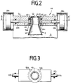
- FIG. 2 is a sealing closure 44 for locking of the container 2 according to a second embodiment shown.
- the container head 40 with its external thread 50 in a in the head part 54 of the Coating device arranged insert 65 used.
- the container 2 For sealing the interior of the container 12 opposite the container exterior 14 is the container 2 by means of two against each other slidable and diametrically opposite each other arranged slide 56a, 56b with against the circumferential sealing surface 52 against the insert 65 pressed, the slide 56a, 56b against the inclined lower surface of the container collar 48 slide and this with the container 2 in a direction towards the head part 54 Preferred direction to be shifted.
- FIG. 4a and 4b is a further sealing closure 70 in the locking position (Fig. 4b) and in a feed or removal position (Fig. 4a).
- the seal 70 consists in essentially from a stationary on the headboard 54 arranged adapter holder 72.
- the adapter holder 72 has a through opening 74, which are essentially congruent to that in the head part 54 recessed opening 4 is arranged is.
- an adapter 76 is placed on the container head 40 screwed to the external thread 50 of the container 2. On the face side, the adapter 76 lies with a circumferential sealing element 79 on the front Sealing surface 52 of the container 2 (see Fig. 4a).
- Transport devices become the container 2 with adapter 76 attached to the adapter receptacle in the loading direction shown in Fig. 4a R used, the adapter 76 with its End face a recessed in the adapter receptacle 72 Compresses the ring spring in its end position.
- the outer lateral surface of the adapter 76 lies sealingly on a circumferential sealing element 71, which in the adapter receptacle 72 in a Groove is fixed. Since the adapter holder 72 at the same time as that surrounding the opening 4 Sealing element rests on the outside of the container 14 of the container interior 12 completely sealed off.
- a Adapter receptacle 72 surrounding and axially on this slidably mounted locking ring 73 of the Head part 54 by an electromagnetically exerted Force moved away.
- electromagnets 86a, 86b can be positioned.
- Electromagnets 86a and 86b activated in such a way that the locking ring 73 with the support of between the locking ring 73 and the adapter receptacle 72 arranged spring 77 in that shown in Fig. 4b Locked position is held.
- the adapter receptacle 76 in ball bearings arranged locking balls 90a, 90b in the in the Press and lock adapter 76 molded backdrops the adapter 76 in the adapter receptacle 72.
- the container exterior becomes as above evacuated described, the container interior 12 flows with a cooling medium becomes.
- the adapter 76 is directed towards the head part 54 Movement of the locking ring 73 unlocked.
- the unlocked adapter is biased by the Spring 82 pushed out of adapter receptacle 72, to be transported further to become.
- Detaching the container 2 from the Sealing closure 70 can here by the openings 4.74 directed into the container interior 12 Pressure surge of a gas are supported.
- the electromagnets are in the unlocked position 86a and 86b activated in such a way that between the permanent magnets 84a and 84b and the electromagnets 86a on the one hand and 86b on the other hand an attractive electromagnetic force is exercised.
Landscapes
- Chemical & Material Sciences (AREA)
- Engineering & Computer Science (AREA)
- Physics & Mathematics (AREA)
- Plasma & Fusion (AREA)
- General Chemical & Material Sciences (AREA)
- Materials Engineering (AREA)
- Organic Chemistry (AREA)
- Chemical Kinetics & Catalysis (AREA)
- Mechanical Engineering (AREA)
- Metallurgy (AREA)
- Spectroscopy & Molecular Physics (AREA)
- Electromagnetism (AREA)
- Analytical Chemistry (AREA)
- Life Sciences & Earth Sciences (AREA)
- Geochemistry & Mineralogy (AREA)
- Chemical Vapour Deposition (AREA)
- Details Of Rigid Or Semi-Rigid Containers (AREA)
- Containers Having Bodies Formed In One Piece (AREA)
- Application Of Or Painting With Fluid Materials (AREA)
Applications Claiming Priority (2)
| Application Number | Priority Date | Filing Date | Title |
|---|---|---|---|
| DE19722205 | 1997-05-27 | ||
| DE19722205A DE19722205A1 (de) | 1997-05-27 | 1997-05-27 | Verfahren und Vorrichtung zur Beschichtung von Kunststoff- oder Glasbehältern mittels eines PCVD-Beschichtungsverfahrens |
Publications (2)
| Publication Number | Publication Date |
|---|---|
| EP0881197A2 true EP0881197A2 (fr) | 1998-12-02 |
| EP0881197A3 EP0881197A3 (fr) | 1999-07-28 |
Family
ID=7830656
Family Applications (1)
| Application Number | Title | Priority Date | Filing Date |
|---|---|---|---|
| EP98106672A Withdrawn EP0881197A3 (fr) | 1997-05-27 | 1998-04-11 | Appareil et procédé de revêtement d'un récipiant en verre ou en plastique au moyen de plasma CVD |
Country Status (5)
| Country | Link |
|---|---|
| US (1) | US6242053B1 (fr) |
| EP (1) | EP0881197A3 (fr) |
| JP (1) | JPH10330945A (fr) |
| CN (1) | CN1200381A (fr) |
| DE (1) | DE19722205A1 (fr) |
Cited By (16)
| Publication number | Priority date | Publication date | Assignee | Title |
|---|---|---|---|---|
| FR2773796A1 (fr) * | 1998-01-20 | 1999-07-23 | Schott Glas | Procede de fabrication d'un corps moule en verre, creux, pourvu d'un revetement interieur et tube de verre en tant que produit semi-fini pour la realisation dudit corps moule en verre |
| FR2792854A1 (fr) * | 1999-04-29 | 2000-11-03 | Sidel Sa | Dispositif pour le depot par plasma micro-ondes d'un revetement sur un recipient en materiau thermoplastique |
| EP1050517A1 (fr) * | 1999-05-07 | 2000-11-08 | Schott Glas | Récipient en verre pour utilisation médicinale |
| DE19957744A1 (de) * | 1999-12-01 | 2001-06-07 | Tetra Laval Holdings & Finance | Vorrichtung zum Abdichten des Stirnrandes eines Behälterhalses |
| DE10001936A1 (de) * | 2000-01-19 | 2001-07-26 | Tetra Laval Holdings & Finance | Einkoppelanordnung für Mikrowellenenergie mit Impedanzanpassung |
| EP1126504A1 (fr) * | 2000-02-18 | 2001-08-22 | European Community | Procédé et dispositif de traitement par plasma à couplage inductif |
| DE10026540A1 (de) * | 2000-05-27 | 2001-11-29 | Gfe Met & Mat Gmbh | Gegenstand, insbesondere Implantat |
| EP1220281A3 (fr) * | 2000-12-25 | 2007-01-17 | Toyo Seikan Kaisya, Ltd. | Procédé de traitement par plasma microonde |
| WO2009121324A1 (fr) * | 2008-03-31 | 2009-10-08 | Khs Corpoplast Gmbh & Co. Kg | Dispositif de traitement de pièces au plasma |
| DE102004020185B4 (de) * | 2004-04-22 | 2013-01-17 | Schott Ag | Verfahren und Vorrichtung für die Innenbeschichtung von Hohlkörpern sowie Verwendung der Vorrichtung |
| EP2626445A1 (fr) | 2012-02-09 | 2013-08-14 | Krones AG | Lance à gaz à cathodes creuses pour le revêtement interne de récipients |
| DE102012201955A1 (de) | 2012-02-09 | 2013-08-14 | Krones Ag | Powerlanze und plasmaunterstützte Beschichtung mit Hochfrequenzeinkopplung |
| EP2641995A1 (fr) | 2012-03-23 | 2013-09-25 | Krones AG | Soupape d'aspiration dans un dispositif de revêtement par plasma |
| DE102012206081A1 (de) | 2012-04-13 | 2013-10-17 | Krones Ag | Beschichtung von Behältern mit Plasmadüsen |
| US8747962B2 (en) | 2005-08-24 | 2014-06-10 | Schott Ag | Method and device for the internal plasma treatment of hollow bodies |
| WO2021224290A1 (fr) * | 2020-05-06 | 2021-11-11 | Khs Gmbh | Dispositif et procédé pour revêtement de récipients |
Families Citing this family (13)
| Publication number | Priority date | Publication date | Assignee | Title |
|---|---|---|---|---|
| DE19726663A1 (de) * | 1997-06-23 | 1999-01-28 | Sung Spitzl Hildegard Dr Ing | Vorrichtung zur Erzeugung von homogenen Mikrowellenplasmen |
| DE10130666A1 (de) * | 2001-06-28 | 2003-01-23 | Applied Films Gmbh & Co Kg | Softcoat |
| DE10221461B4 (de) * | 2002-05-15 | 2004-05-06 | Schott Glas | Vorrichtung und Verwendung einer Vorrichtung zum Aufnehmen und Vakuumabdichten eines Behältnisses mit einer Öffnung |
| US20040142572A1 (en) * | 2003-01-16 | 2004-07-22 | Deveau Jason S. T. | Apparatus and method for selectively inducing hydrophobicity in a single barrel of a multibarrel ion selective microelectrode |
| US20060172085A1 (en) * | 2003-03-12 | 2006-08-03 | Toyo Seikan Kaisha, Ltd | Method and apparatus for chemical plasma processing of plastic container |
| DE10354625A1 (de) * | 2003-11-22 | 2005-06-30 | Sig Technology Ltd. | Verfahren zur Bestimmung der Gasdurchlässigkeit von Behälterwandungen, Behälter mit Oberflächenbeschichtung sowie Beschichtungseinrichtung mit Messvorrichtung |
| FR2872144B1 (fr) * | 2004-06-24 | 2006-10-13 | Sidel Sas | Machine de traitement de recipients comportant des moyens de prehension commandes pour saisir les recipients par leur col |
| US20060070677A1 (en) * | 2004-09-28 | 2006-04-06 | Tokai Rubber Industries, Ltd. | Hose with sealing layer, direct-connect assembly including the same, and method of manufacturing the same |
| FR2907531B1 (fr) * | 2006-10-18 | 2009-02-27 | Sidel Participations | Dispositif a double etancheite pour une machine de traitement de recipients par plasma |
| WO2009036579A1 (fr) * | 2007-09-21 | 2009-03-26 | Hoffmann Neopac Ag | Appareil pour revêtement appliqué sous plasma de la surface interne de contenants d'emballage tubulaires en matière plastique au moyen d'un faisceau-plasma non thermique à pression ambiante réactive |
| JP2013214445A (ja) * | 2012-04-03 | 2013-10-17 | Ihi Corp | プラズマ処理装置 |
| CN108421792A (zh) * | 2018-05-08 | 2018-08-21 | 江苏新美星包装机械股份有限公司 | 内洗机中水桶的托持机构 |
| CN115416276A (zh) * | 2022-09-20 | 2022-12-02 | 湖南千山制药机械股份有限公司 | 包装盖真空内镀模组及连续真空内镀机 |
Family Cites Families (12)
| Publication number | Priority date | Publication date | Assignee | Title |
|---|---|---|---|---|
| FR2592874B1 (fr) * | 1986-01-14 | 1990-08-03 | Centre Nat Rech Scient | Procede pour tremper un objet en verre ou vitreux et objet ainsi trempe |
| US5041303A (en) * | 1988-03-07 | 1991-08-20 | Polyplasma Incorporated | Process for modifying large polymeric surfaces |
| CA2060917A1 (fr) * | 1991-03-12 | 1992-09-13 | Milam Pender | Dispositif de depot de vapeur chimique, ameliore par le plasma |
| MX9303141A (es) * | 1992-05-28 | 1994-04-29 | Polar Materials Inc | Metodos y aparatos para depositar recubrimientos de barrera. |
| US5308649A (en) * | 1992-06-26 | 1994-05-03 | Polar Materials, Inc. | Methods for externally treating a container with application of internal bias gas |
| DE4318084A1 (de) * | 1993-06-01 | 1994-12-08 | Kautex Werke Gmbh | Verfahren und Einrichtung zum Herstellen einer polymeren Deckschicht in Kunststoff-Hohlkörpern |
| CH687601A5 (de) * | 1994-02-04 | 1997-01-15 | Tetra Pak Suisse Sa | Verfahren zur Herstellung von im Innern sterilen Verpackungen mit hervorragenden Sperreigenschaften. |
| US5565248A (en) * | 1994-02-09 | 1996-10-15 | The Coca-Cola Company | Method and apparatus for coating hollow containers through plasma-assisted deposition of an inorganic substance |
| DE4404690A1 (de) * | 1994-02-15 | 1995-08-17 | Leybold Ag | Verfahren zur Erzeugung von Sperrschichten für Gase und Dämpfe auf Kunststoff-Substraten |
| ES2131810T5 (es) * | 1994-02-16 | 2004-02-16 | The Coca-Cola Company | Recipientes huecos con superficies interiores inertes o impermeables producidas por reaccion superficial asistida por plasma o polimerizacion sobre la superficie. |
| DE4438359C2 (de) * | 1994-10-27 | 2001-10-04 | Schott Glas | Behälter aus Kunststoff mit einer Sperrbeschichtung |
| DE19629877C1 (de) * | 1996-07-24 | 1997-03-27 | Schott Glaswerke | CVD-Verfahren und Vorrichtung zur Innenbeschichtung von Hohlkörpern |
-
1997
- 1997-05-27 DE DE19722205A patent/DE19722205A1/de not_active Withdrawn
-
1998
- 1998-04-11 EP EP98106672A patent/EP0881197A3/fr not_active Withdrawn
- 1998-05-20 US US09/081,209 patent/US6242053B1/en not_active Expired - Fee Related
- 1998-05-26 CN CN98108970A patent/CN1200381A/zh active Pending
- 1998-05-27 JP JP14620498A patent/JPH10330945A/ja active Pending
Cited By (23)
| Publication number | Priority date | Publication date | Assignee | Title |
|---|---|---|---|---|
| FR2773796A1 (fr) * | 1998-01-20 | 1999-07-23 | Schott Glas | Procede de fabrication d'un corps moule en verre, creux, pourvu d'un revetement interieur et tube de verre en tant que produit semi-fini pour la realisation dudit corps moule en verre |
| US7670453B1 (en) | 1999-04-29 | 2010-03-02 | Sidel Participations | Device for treating a container with microwave plasma |
| FR2792854A1 (fr) * | 1999-04-29 | 2000-11-03 | Sidel Sa | Dispositif pour le depot par plasma micro-ondes d'un revetement sur un recipient en materiau thermoplastique |
| WO2000066804A1 (fr) * | 1999-04-29 | 2000-11-09 | Sidel Actis Services | Dispositif pour le traitement d'un recipient par plasma micro-ondes |
| EP1050517A1 (fr) * | 1999-05-07 | 2000-11-08 | Schott Glas | Récipient en verre pour utilisation médicinale |
| US6599594B1 (en) | 1999-05-07 | 2003-07-29 | Schott Glas | Glass container for medicinal purposes |
| DE19957744A1 (de) * | 1999-12-01 | 2001-06-07 | Tetra Laval Holdings & Finance | Vorrichtung zum Abdichten des Stirnrandes eines Behälterhalses |
| DE10001936A1 (de) * | 2000-01-19 | 2001-07-26 | Tetra Laval Holdings & Finance | Einkoppelanordnung für Mikrowellenenergie mit Impedanzanpassung |
| EP1126504A1 (fr) * | 2000-02-18 | 2001-08-22 | European Community | Procédé et dispositif de traitement par plasma à couplage inductif |
| WO2001061726A1 (fr) * | 2000-02-18 | 2001-08-23 | European Community (Ec) | Procede et appareil de traitement au plasma couple de facon inductive |
| DE10026540A1 (de) * | 2000-05-27 | 2001-11-29 | Gfe Met & Mat Gmbh | Gegenstand, insbesondere Implantat |
| EP1220281A3 (fr) * | 2000-12-25 | 2007-01-17 | Toyo Seikan Kaisya, Ltd. | Procédé de traitement par plasma microonde |
| DE102004020185B4 (de) * | 2004-04-22 | 2013-01-17 | Schott Ag | Verfahren und Vorrichtung für die Innenbeschichtung von Hohlkörpern sowie Verwendung der Vorrichtung |
| US8747962B2 (en) | 2005-08-24 | 2014-06-10 | Schott Ag | Method and device for the internal plasma treatment of hollow bodies |
| WO2009121324A1 (fr) * | 2008-03-31 | 2009-10-08 | Khs Corpoplast Gmbh & Co. Kg | Dispositif de traitement de pièces au plasma |
| EP2626445A1 (fr) | 2012-02-09 | 2013-08-14 | Krones AG | Lance à gaz à cathodes creuses pour le revêtement interne de récipients |
| DE102012201955A1 (de) | 2012-02-09 | 2013-08-14 | Krones Ag | Powerlanze und plasmaunterstützte Beschichtung mit Hochfrequenzeinkopplung |
| DE102012201956A1 (de) | 2012-02-09 | 2013-08-14 | Krones Ag | Hohlkathoden-Gaslanze für die Innenbeschichtung von Behältern |
| EP2626446A1 (fr) | 2012-02-09 | 2013-08-14 | Krones AG | Lance d'alimentation et revêtement assisté par plasma avec couplage à haute fréquence |
| EP2641995A1 (fr) | 2012-03-23 | 2013-09-25 | Krones AG | Soupape d'aspiration dans un dispositif de revêtement par plasma |
| DE102012204689A1 (de) | 2012-03-23 | 2013-09-26 | Krones Ag | Absaugventil in Plasmabeschichtungsvorrichtung |
| DE102012206081A1 (de) | 2012-04-13 | 2013-10-17 | Krones Ag | Beschichtung von Behältern mit Plasmadüsen |
| WO2021224290A1 (fr) * | 2020-05-06 | 2021-11-11 | Khs Gmbh | Dispositif et procédé pour revêtement de récipients |
Also Published As
| Publication number | Publication date |
|---|---|
| JPH10330945A (ja) | 1998-12-15 |
| EP0881197A3 (fr) | 1999-07-28 |
| CN1200381A (zh) | 1998-12-02 |
| US6242053B1 (en) | 2001-06-05 |
| DE19722205A1 (de) | 1998-12-03 |
Similar Documents
| Publication | Publication Date | Title |
|---|---|---|
| EP0881197A2 (fr) | Appareil et procédé de revêtement d'un récipiant en verre ou en plastique au moyen de plasma CVD | |
| EP2050120B1 (fr) | Source de plasma ecr | |
| DE60022377T2 (de) | Vakuumsystem für eine vorrichtung zur behandlung eines behälters mittels niederdruckplasma | |
| DE69626782T9 (de) | Verfahren und gerät zur plasmabearbeitung | |
| DE10202311B4 (de) | Vorrichtung und Verfahren zur Plasmabehandlung von dielektrischen Körpern | |
| EP0708185B1 (fr) | Appareil pour traiter la surface d'un objet, notamment la surface interne des réservoirs de carburant | |
| EP1507887B1 (fr) | Dispositif comprenant de multiples emplacements pour l'application de revetement multiplace et procede de revetement par plasma | |
| DE69705552T2 (de) | Verfahren zur Plasmaverarbeitung | |
| EP2041332B1 (fr) | Procédé et dispositif de séparation chimique en phase gazeuse assistée par plasma sur la paroi intérieure d'un corps creux | |
| EP1412101B1 (fr) | Procede et dispositif permettant simultanement de mouler un corps et de former un revetement sur ce corps | |
| EP0778089A1 (fr) | Système d'application d'un revêtement polymère sur la surface intérieure de corps creux en matière plastique | |
| DE3011686A1 (de) | Vorrichtung zur plasma-oberflaechenbehandlung von werkstoffen | |
| DE102011009057A1 (de) | Plasma-Behandlungsvorrichtung zur Herstellung von Beschichtungen | |
| EP2046506B1 (fr) | Procédé de traitement plasma d'une surface | |
| DE60003690T2 (de) | Vorrichtung zum behandeln eines behälters mit einem mikrowellen-plasma | |
| DE3414539C2 (fr) | ||
| EP2641995A1 (fr) | Soupape d'aspiration dans un dispositif de revêtement par plasma | |
| EP0739655B1 (fr) | Procédé pour revêtir à l'aide d'un plasma un objet en plastique de couches multifonctionnelles | |
| DE102013109778A1 (de) | Verfahren und Vorrichtung zur kontinuierlichen Wiederaufbereitung von Abgas eines Fusionsreaktors | |
| DE10138697B4 (de) | Verfahren und Vorrichtung zum Beschichten und Spritzblasen eines dreidimensionalen Körpers | |
| EP0801952A2 (fr) | Appareil pour la stérilisation des surfaces intérieures de récipients sensibles à la pression | |
| DE4414083C2 (de) | Vorrichtung zum Herstellen dünner Schichten auf Kunststoff-Substraten und zum Ätzen solcher Substrate | |
| Nakagawa et al. | Production of highly charged metal ion beams from organic metal compounds at RIKEN 18 GHz ECRIS | |
| DE10236683A1 (de) | Vorrichtung zur Plasmabehandlung von Hohlkörpern, insbesondere Flaschen | |
| DE3844630C2 (fr) |
Legal Events
| Date | Code | Title | Description |
|---|---|---|---|
| PUAI | Public reference made under article 153(3) epc to a published international application that has entered the european phase |
Free format text: ORIGINAL CODE: 0009012 |
|
| AK | Designated contracting states |
Kind code of ref document: A2 Designated state(s): AT DE DK ES FI FR GB GR IT NL |
|
| AX | Request for extension of the european patent |
Free format text: AL;LT;LV;MK;RO;SI |
|
| PUAL | Search report despatched |
Free format text: ORIGINAL CODE: 0009013 |
|
| AK | Designated contracting states |
Kind code of ref document: A3 Designated state(s): AT BE CH CY DE DK ES FI FR GB GR IE IT LI LU MC NL PT SE |
|
| AX | Request for extension of the european patent |
Free format text: AL;LT;LV;MK;RO;SI |
|
| RIC1 | Information provided on ipc code assigned before grant |
Free format text: 6C 03C 17/00 A, 6B 05D 7/24 B |
|
| 17P | Request for examination filed |
Effective date: 19990812 |
|
| AKX | Designation fees paid |
Free format text: AT DE DK ES FI FR GB GR IT NL |
|
| 17Q | First examination report despatched |
Effective date: 20001206 |
|
| STAA | Information on the status of an ep patent application or granted ep patent |
Free format text: STATUS: THE APPLICATION IS DEEMED TO BE WITHDRAWN |
|
| 18D | Application deemed to be withdrawn |
Effective date: 20010619 |