EP0881720B1 - Apparatus for assembling grommet to lead - Google Patents
Apparatus for assembling grommet to lead Download PDFInfo
- Publication number
- EP0881720B1 EP0881720B1 EP19980109293 EP98109293A EP0881720B1 EP 0881720 B1 EP0881720 B1 EP 0881720B1 EP 19980109293 EP19980109293 EP 19980109293 EP 98109293 A EP98109293 A EP 98109293A EP 0881720 B1 EP0881720 B1 EP 0881720B1
- Authority
- EP
- European Patent Office
- Prior art keywords
- grommet
- pin
- wire
- sleeve
- assembly
- Prior art date
- Legal status (The legal status is an assumption and is not a legal conclusion. Google has not performed a legal analysis and makes no representation as to the accuracy of the status listed.)
- Expired - Lifetime
Links
- 238000012546 transfer Methods 0.000 claims description 20
- 238000003780 insertion Methods 0.000 claims description 7
- 230000037431 insertion Effects 0.000 claims description 7
- 230000014759 maintenance of location Effects 0.000 description 4
- 238000000034 method Methods 0.000 description 3
- 238000010276 construction Methods 0.000 description 2
- 230000003287 optical effect Effects 0.000 description 2
- 238000012545 processing Methods 0.000 description 2
- 230000003213 activating effect Effects 0.000 description 1
- 230000002411 adverse Effects 0.000 description 1
- 238000004891 communication Methods 0.000 description 1
- 238000002788 crimping Methods 0.000 description 1
- 230000001105 regulatory effect Effects 0.000 description 1
- 238000007789 sealing Methods 0.000 description 1
Images



Classifications
-
- H—ELECTRICITY
- H01—ELECTRIC ELEMENTS
- H01R—ELECTRICALLY-CONDUCTIVE CONNECTIONS; STRUCTURAL ASSOCIATIONS OF A PLURALITY OF MUTUALLY-INSULATED ELECTRICAL CONNECTING ELEMENTS; COUPLING DEVICES; CURRENT COLLECTORS
- H01R43/00—Apparatus or processes specially adapted for manufacturing, assembling, maintaining, or repairing of line connectors or current collectors or for joining electric conductors
- H01R43/005—Apparatus or processes specially adapted for manufacturing, assembling, maintaining, or repairing of line connectors or current collectors or for joining electric conductors for making dustproof, splashproof, drip-proof, waterproof, or flameproof connection, coupling, or casing
Definitions
- This invention relates to an apparatus for assembling seal grommets onto wires, for example electrical or optical leads.
- a grommet assembly apparatus for assembling grommets on leads, the apparatus comprising a grommet receiving device comprising a hollow sleeve having a cavity extending therethrough for receiving a lead or wire therein, an outer surface of the tube for receiving a grommet elastically compressed thereagainst for assembly onto the lead, the apparatus further comprising a pin insertable in the wire receiving cavity of the hollow sleeve for assisting assembly of the grommet onto the outer surface of the hollow sleeve, the pin having a tapered leading end in order to guide insertion of the pin through the grommet, wherein the pin leading end is insertable into the sleeve from the wire receiving end thereof.
- air may be blown out of the sleeve cavity in order to assist pushing of the grommet over the pin until abutment of the grommet against a stop, and subsequent insertion of the sleeve into the grommet central cavity causing resilient expansion thereof.
- the pin device may be provided in alignment with an end of a grommet supply device, such as a grommet supply channel, such that the pin device can pick the grommet directly from the supply device and insert it directly onto the grommet expansion sleeve.
- a grommet supply device such as a grommet supply channel
- a grommet assembly apparatus 2 is shown mounted on a base 4 and upstanding vertically (along the Y axis). The horizontal axis is defined as the axis X.
- a conveyor apparatus 6 is also fixed to the base 4 of a harness making machine via the support 8.
- the conveyor system 6 has a plurality of grippers 10 for gripping and conveying leads or wires 12 of electrical or optical cables.
- the grippers 10 are conveyed in a direction Z perpendicular to the X and Y directions, for transporting the wires 12 to various wire processing stations of the harness making machine, such as stations for cutting the wires ends, stations for crimping terminals to the wires ends, stations for inserting the wires ends into connectors housings etc.
- One of the wire processing stations is the grommet assembly apparatus 2 for positioning grommet seals on the wire ends for the purpose of sealing the wires in corresponding cavities of a connector housing.
- a grommet 14 is shown assembled onto an end 15 of the wire 12.
- the grommet assembly apparatus 2 comprises a fixed structure 16 mounted on the base 4. Fixed to the structure 16 is a primary motor 18 that drives a piston or rod 20 in the horizontal direction X. A slide 22 is also mounted in a fixed manner to the structure 16. A gripper device 24 comprising a support structure 25 and movable jaws 26,27 is fixed to the primary piston 20. The gripper device 24 is therefore movable in the X direction by means of the motor 18. The movable jaws 26,27 are movable in a vertical direction towards and away from each other by means of a motor (not shown) mounted on the gripper support 25.
- the upper jaw 26 is shown separated from the gripper device, but in fact it is mounted within a portion of the support 25 that forms a single assembled structure movably fixed to the rod 20.
- the gripper support 25 is slidably mounted on a slide 30 extending in the X direction and rigidly fixed to the apparatus support 16.
- a grommet mounting device 32 comprises a mounting device support 34 that is slidably mounted in the X direction on the fixed slide 22, the device further comprising a grommet receiving member 36 rotatably mounted about a Z axis to the device support 34 as indicated by the mounting portion 38.
- a secondary motor 40 is mounted in a fixed manner to the grommet mounting device support 34, and drives a secondary piston or rod 42 in the X direction.
- the secondary rod 42 is secured to the gripper support 25 such that the gripper device 24 and the grommet mounting device 32 are relatively slidable in the X direction with respect to each other and with respect to the apparatus fixed structure 16.
- the grommet assembly apparatus further comprises a grommet transport device having a grommet supply of feed channel 44 that feeds grommets 14 to an end 46 of the channel 44 for mounting on the grommet receiving member 36.
- the grommets 14 are positioned vertically in the feed channel 44 proximite the end 46, such that central channels 48 traversing the grommets 14 extend in the Y direction.
- the apparatus further comprises a grommet transfer device 50 for transferring and loading grommets 14 on to the mounting device 32.
- the transfer device 50 comprises a motor 52 that drives a grommet transfer element 54 in the vertical direction Y.
- the transfer element 54 is provided in alignment with a grommet 14 at the end portion 46 of the feed channel 44.
- the transfer element 54 is shown comprising a pin 56 extending to a free end 58, and a stop 60 concentrically surrounding the pin 56 at a certain distance remote from the free end 58 for providing an abutment surface to limit insertion of the grommet 14 along the pin 56.
- the free end 58 is pointed and extends towards the stop 60 in a tapered or conical manner, thereby providing a smooth guide or insertion tip 62 for smoothly inserting and locating in the central cavity 48 of the grommet 14.
- the rotatable grommet receiving mounting device 36 comprises a chamber 64 positioned centrally within a housing 66, the device further comprising a grommet expansion sleeve 68 attached to the housing 66 and forming a cavity 70 extending therethrough in communication with the chamber 64.
- the cavity 70 is a wire receiving cavity which is also adapted to receive the transfer pin 56 therein as shown in figures 9 and 10, during mounting of the grommet 14 on the expansion sleeve 68.
- the chamber 64 is supplied with compressed air through a supply channel 72 which is connected to a flexible tube (not shown) for supplying the compressed air into the chamber 64.
- the compressed air may be supplied intermittently during operation by automatically regulated control valves.
- a grommet 14 in abutment against the end 46 of the feed channel 44 is in alignment with the transfer element 54.
- the transfer element 54 is driven in the Y direction towards to the grommet 14 whereby the tip 58, 62 of the pin 56 is inserted partially into the grommet central cavity 48.
- the movement of the pin 56 and partial engagement in the grommet cavity 48 pushes the grommet 14 through the exit cut-out 78 in the bottom wall 80 of the feed channel 44.
- the grommet outer diameter is slightly larger than the cut-out 78 such that the grommet remains within the feed channel 44 until pushed by the transfer element.
- the transfer element 54 is driven along the Y axis until the grommet 14 abuts the stop 60 and the expansion sleeve 68 is subsequently inserted between the grommet and the pin 56.
- the grommet is thereby elastically expanded over the outer surface 84 of the expansion sleeve 68.
- a recess 90 extends into the transfer element 54 between the pin 56 and a concentric wall 88 that forms the abutment shoulder 60 in order to allow extension of the expansion sleeve 68 therein.
- the concentric wall 88 may be provided with a cavity 89 to allow air to escape from the recess or cavity 90 if necessary.
- the primary rod 20 and the secondary rod 42 are both in retracted positions, and the grommet receiving member 36 is in the vertical position in alignment with the transfer element 54.
- a grommet 14 is then mounted on the expansion sleeve 68 as previously described with reference to figure 9 and 10, and as depicted in figure 2.
- the grommet receiving member 36 is rotated 90 degrees to the horizontal position in alignment with a wire 12 carried by the conveying system to the grommet assembly apparatus.
- the expansion sleeve 68 is received within a U-shaped recess 92 of a retention wall 94 (see figure 8a) that serves to retain the seal in an axial position along the X axis with respect to the gripper device 24.
- the U-shaped recess 92 of the retention wall 94 has a smaller radius than the grommet 14, such that when the expansion sleeve 68 is retracted with respect to the retention wall 94, the grommet slides off the expansion tube.
- the jaws 26,27 are closed towards to each other.
- the jaws 26,27 are provided with a funnel shaped wire guide surface 96 that serves to guide the end 15 of the wire 12 into the expansion sleeve cavity 70 as shown in figure 5. Insertion of the wire end 15 into the cavity 70 is effected by activating the motor 18 and driving the primary road 20 to an extended position. Both the gripper device 24 and the mounting device 32 slide on their slides 30,22 respectively.
- the secondary rod 42 is driven into the extended position by the secondary motor 40 such that the mounting device 32 is retracted relative to the gripper device 24, such that the retention wall 94 of the gripper pulls the grommet 14 off the expansion sleeve and onto the wire 12.
- the jaws 26,27 are moved to the open position as shown in figure 6, and the primary motor 18 subsequently driving the primary rod 20 to the initial retracted position such that the wire end 15 is freed.
- the wire end can then be moved by the conveyor system and a new wire presented before the grommet assembly apparatus.
- the secondary rod 42 is also driven to the retracted position by the secondary motor 40, and the grommet receiving member 36 rotated to the vertical position such a new cycle may commence.
Landscapes
- Engineering & Computer Science (AREA)
- Manufacturing & Machinery (AREA)
- Installation Of Indoor Wiring (AREA)
- Automatic Assembly (AREA)
- Insulating Bodies (AREA)
Description
- This invention relates to an apparatus for assembling seal grommets onto wires, for example electrical or optical leads.
- There are various methods of assembling an elastic seal grommet onto a lead, for example by: simply pushing the lead through the seal as described in EP 159006; or projecting the seal with compressed air onto the lead as described US 5007164 and EP 290721, or by fitting the seal on a hollow tube or sleeve in which the lead is received, and subsequently pushing the seal off the tube onto the lead. The latter seal assembly method for example is described in US 5016346 or EP 462923. This method is particularly reliable because the lead is received safely within the grommet expansion sleeve prior to mounting of the seal on the lead. The risk of buckling of the lead, particularly for very thin leads, is thereby eliminated. One of the problems with the latter assembly device is that the seal expansion pins and sleeves are small parts moving relative to each other and requiring high precision. The cost and life time of the machine is adversely effected by relatively delicate movable parts.
- It would also be desirable to provide a particularly flexible seal assembly machine that can easily adapt to automated assembly of various seals and wires such that complete cable harnesses can be automatically processed. An important feature of flexible assembly machines is the ability to modify assembly operations rapidly, with a minimum of tooling changes.
- It is an object of this invention to provide a grommet assembly apparatus that is simple, yet reliable and versatile, for automated assembly.
- Objects of this invention have been achieved by providing the grommet assembly apparatus according to
claim 1. Disclosed herein is a grommet assembly apparatus for assembling grommets on leads, the apparatus comprising a grommet receiving device comprising a hollow sleeve having a cavity extending therethrough for receiving a lead or wire therein, an outer surface of the tube for receiving a grommet elastically compressed thereagainst for assembly onto the lead, the apparatus further comprising a pin insertable in the wire receiving cavity of the hollow sleeve for assisting assembly of the grommet onto the outer surface of the hollow sleeve, the pin having a tapered leading end in order to guide insertion of the pin through the grommet, wherein the pin leading end is insertable into the sleeve from the wire receiving end thereof. - Advantageously therefore, a very simple assembly of a grommet onto a sleeve section with few parts, is achieved.
- In order to assist assembly of the grommet onto the sleeve, air may be blown out of the sleeve cavity in order to assist pushing of the grommet over the pin until abutment of the grommet against a stop, and subsequent insertion of the sleeve into the grommet central cavity causing resilient expansion thereof.
- For a particularly simple assembly apparatus, the pin device may be provided in alignment with an end of a grommet supply device, such as a grommet supply channel, such that the pin device can pick the grommet directly from the supply device and insert it directly onto the grommet expansion sleeve.
- Further advantageous aspects of this invention will be apparent from the claims or from the following description and drawings.
- An embodiment of this invention will now be described by way of example with reference to the figures, in which;
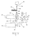
- figures 1-7 are simplified drawings of a grommet assembly apparatus showing the sequence of assembly operations of a grommet onto a lead;
- figure 8 is a simplified view of the seal assembly apparatus;
- figure 8a is a detailed view of grommet receiving abutment profile for removing the grommet from the hollow expansion sleeve;
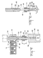
- figure 9 is a partial cross-sectional detailed view of assembly devices for mounting the grommet on a seal expansion sleeve;
- figure 10 a view similar to that of figure 9 in an assembly stage just prior to that of figure 9.
-
- Referring first to figure 8, a
grommet assembly apparatus 2 is shown mounted on abase 4 and upstanding vertically (along the Y axis). The horizontal axis is defined as the axis X. Aconveyor apparatus 6 is also fixed to thebase 4 of a harness making machine via the support 8. Theconveyor system 6 has a plurality ofgrippers 10 for gripping and conveying leads orwires 12 of electrical or optical cables. Thegrippers 10 are conveyed in a direction Z perpendicular to the X and Y directions, for transporting thewires 12 to various wire processing stations of the harness making machine, such as stations for cutting the wires ends, stations for crimping terminals to the wires ends, stations for inserting the wires ends into connectors housings etc. One of the wire processing stations is thegrommet assembly apparatus 2 for positioning grommet seals on the wire ends for the purpose of sealing the wires in corresponding cavities of a connector housing. In figure 8, agrommet 14 is shown assembled onto anend 15 of thewire 12. - The
grommet assembly apparatus 2 comprises afixed structure 16 mounted on thebase 4. Fixed to thestructure 16 is aprimary motor 18 that drives a piston orrod 20 in the horizontal direction X. Aslide 22 is also mounted in a fixed manner to thestructure 16. Agripper device 24 comprising asupport structure 25 andmovable jaws primary piston 20. Thegripper device 24 is therefore movable in the X direction by means of themotor 18. Themovable jaws gripper support 25. For clarity, theupper jaw 26 is shown separated from the gripper device, but in fact it is mounted within a portion of thesupport 25 that forms a single assembled structure movably fixed to therod 20. In order to provide stabil support of thedevice 24, thegripper support 25 is slidably mounted on aslide 30 extending in the X direction and rigidly fixed to theapparatus support 16. - A
grommet mounting device 32 comprises amounting device support 34 that is slidably mounted in the X direction on thefixed slide 22, the device further comprising agrommet receiving member 36 rotatably mounted about a Z axis to thedevice support 34 as indicated by themounting portion 38. Asecondary motor 40 is mounted in a fixed manner to the grommetmounting device support 34, and drives a secondary piston orrod 42 in the X direction. Thesecondary rod 42 is secured to thegripper support 25 such that thegripper device 24 and thegrommet mounting device 32 are relatively slidable in the X direction with respect to each other and with respect to the apparatus fixedstructure 16. - The grommet assembly apparatus further comprises a grommet transport device having a grommet supply of
feed channel 44 that feeds grommets 14 to anend 46 of thechannel 44 for mounting on thegrommet receiving member 36. Thegrommets 14 are positioned vertically in thefeed channel 44 proximite theend 46, such thatcentral channels 48 traversing thegrommets 14 extend in the Y direction. - The apparatus further comprises a
grommet transfer device 50 for transferring andloading grommets 14 on to themounting device 32. Thetransfer device 50 comprises amotor 52 that drives agrommet transfer element 54 in the vertical direction Y. Thetransfer element 54 is provided in alignment with agrommet 14 at theend portion 46 of thefeed channel 44. - Referring to figures 9 and 10 in conjunction with figure 8, transfer of a grommet from the feed channel to the mounting device will now be explained. Referring first to figure 9, the
transfer element 54 is shown comprising apin 56 extending to afree end 58, and astop 60 concentrically surrounding thepin 56 at a certain distance remote from thefree end 58 for providing an abutment surface to limit insertion of thegrommet 14 along thepin 56. Thefree end 58 is pointed and extends towards thestop 60 in a tapered or conical manner, thereby providing a smooth guide orinsertion tip 62 for smoothly inserting and locating in thecentral cavity 48 of thegrommet 14. - The rotatable grommet
receiving mounting device 36 comprises achamber 64 positioned centrally within ahousing 66, the device further comprising agrommet expansion sleeve 68 attached to thehousing 66 and forming acavity 70 extending therethrough in communication with thechamber 64. Thecavity 70 is a wire receiving cavity which is also adapted to receive thetransfer pin 56 therein as shown in figures 9 and 10, during mounting of thegrommet 14 on theexpansion sleeve 68. Thechamber 64 is supplied with compressed air through asupply channel 72 which is connected to a flexible tube (not shown) for supplying the compressed air into thechamber 64. The compressed air may be supplied intermittently during operation by automatically regulated control valves. - Mounting of the
grommet 14 onto theexpansion sleeve 68 is achieved as follows. Agrommet 14 in abutment against theend 46 of thefeed channel 44 is in alignment with thetransfer element 54. Thetransfer element 54 is driven in the Y direction towards to thegrommet 14 whereby thetip pin 56 is inserted partially into the grommetcentral cavity 48. The movement of thepin 56 and partial engagement in thegrommet cavity 48 pushes thegrommet 14 through the exit cut-out 78 in thebottom wall 80 of thefeed channel 44. The grommet outer diameter is slightly larger than the cut-out 78 such that the grommet remains within thefeed channel 44 until pushed by the transfer element. As shown in figure 10, when thegrommet 14 is pushed through the cut-out 78, it is only partly inserted over thetransfer pin 56, and enters into abutment with the free end ortip 82 of theexpansion sleeve 68. The expansion sleeve pushes thegrommet 14 further along thepin 56 towards thestop 60. In order to facilitate pushing of thegrommet 14 along thepin 56 , in particular past theconcial section 62, compressed air is provided in the chamber andcavity grommet 14 at the positions denoted 84 in figure 10. The latter ensures that thefront end 83 of the grommet does not get pinched into thewire receiving cavity 70 of theexpansion sleeve 78. Thetransfer element 54 is driven along the Y axis until thegrommet 14 abuts thestop 60 and theexpansion sleeve 68 is subsequently inserted between the grommet and thepin 56. The grommet is thereby elastically expanded over theouter surface 84 of theexpansion sleeve 68. Continued provision of air pressure in thecavity 70 ensures that the expansion sleeve 68 smoothly inserts between the grommet and thepin 56. Arecess 90 extends into thetransfer element 54 between thepin 56 and aconcentric wall 88 that forms theabutment shoulder 60 in order to allow extension of theexpansion sleeve 68 therein. Theconcentric wall 88 may be provided with acavity 89 to allow air to escape from the recess orcavity 90 if necessary. Once thegrommet 14 is mounted on theexpansion sleeve 68 as shown in figure 9, thetransfer element 54 can than be retracted and a new grommet fed to theend portion 46. - Referring particularly to figures 1-7, assembly of a grommet to a wire will now be described. Initially, as shown in figure 1, the
primary rod 20 and thesecondary rod 42 are both in retracted positions, and thegrommet receiving member 36 is in the vertical position in alignment with thetransfer element 54. Agrommet 14 is then mounted on theexpansion sleeve 68 as previously described with reference to figure 9 and 10, and as depicted in figure 2. After assembly of the grommet on the expansion sleeve as shown in figure 3, thegrommet receiving member 36 is rotated 90 degrees to the horizontal position in alignment with awire 12 carried by the conveying system to the grommet assembly apparatus. In the position of figure 4, theexpansion sleeve 68 is received within aU-shaped recess 92 of a retention wall 94 (see figure 8a) that serves to retain the seal in an axial position along the X axis with respect to thegripper device 24. TheU-shaped recess 92 of theretention wall 94 has a smaller radius than thegrommet 14, such that when theexpansion sleeve 68 is retracted with respect to theretention wall 94, the grommet slides off the expansion tube. - As shown in figure 4, the
jaws jaws wire guide surface 96 that serves to guide theend 15 of thewire 12 into theexpansion sleeve cavity 70 as shown in figure 5. Insertion of thewire end 15 into thecavity 70 is effected by activating themotor 18 and driving theprimary road 20 to an extended position. Both thegripper device 24 and the mountingdevice 32 slide on theirslides - In the next step, as shown in figure 6, the
secondary rod 42 is driven into the extended position by thesecondary motor 40 such that the mountingdevice 32 is retracted relative to thegripper device 24, such that theretention wall 94 of the gripper pulls thegrommet 14 off the expansion sleeve and onto thewire 12. Thejaws primary motor 18 subsequently driving theprimary rod 20 to the initial retracted position such that thewire end 15 is freed. The wire end can then be moved by the conveyor system and a new wire presented before the grommet assembly apparatus. As shown in figure 7 thesecondary rod 42 is also driven to the retracted position by thesecondary motor 40, and thegrommet receiving member 36 rotated to the vertical position such a new cycle may commence. - It is particularly advantageous to move the expansion sleeve towards the wire, rather than moving the wire such that a simple conveying system may be provided. In other words, the wire may be held in a fixed relation with respect to
grippers 10 of the conveyingsystem 6 whereas the assembly movements are provided by the grommet assembly apparatus. A simpler harness making machine and conveying system is thus provided. Further advantageous is the simple assembly of grommet to the expansion sleeve, and in particular the relatively simple construction of the expansion sleeve mechanism which does not require complex internal movable pins and sleeves. The transfer element is of relatively simple construction and operation. Rotation of the grommet mounting device and transport of the grommet on the expansion sleeve also provides a relatively versatile adaptable system that enables picking and transferring a grommet from supply channel remote from the wire, to the wire.
Claims (10)
- A grommet assembly apparatus (2) for assembling grommets (14) on leads (12), the apparatus comprising a grommet mounting device (32) comprising a hollow sleeve (68) having a cavity (70) extending therethrough for receiving a lead (12) therein, an outer surface (84) of the sleeve for receiving a grommet (14) elastically compressed thereagainst for assembly onto the lead, the apparatus further comprising a pin (56) insertable in the wire receiving cavity (70) of the hollow sleeve for assisting assembly of the grommet onto the outer surface (84) of the sleeve, the pin having a tapered end (62) in order to guide insertion of the pin through the grommet, characterised in that the pin (56) serves as a transferring element of the grommets from the grommet transport device onto the mounting device, and is insertable into the hollow sleeve from a wire receiving end (82) thereof.
- The assembly apparatus of claim 1 wherein air is blown out of the sleeve (68) in order to assist pushing of the grommet (14) over the pin (56).
- The apparatus of claim 1 or 2 wherein the pin (56) is provided on a transfer element (54) movable in a direction (Y) along an axis aligned with a grommet (14) positioned in a loading position (46) of a grommet feed channel (44) arranged between the expansion sleeve and a transfer device (50) that drives the transfer element (54).
- The apparatus of any one of the preceding claims wherein the expansion sleeve (68) is provided on a grommet receiving member (36) device rotatably mounted on a grommet mounting device (32).
- The apparatus of claim 4 wherein the grommet mounting device (32) is slidably mounted in a direction (X) parallel to a wire end (15) of a wire end (12) to be processed, on a slide (22) fixed to a fixed structure (16) of the apparatus.
- The apparatus of any one of the preceding claims wherein the pin (56) is part of a movable transfer element (54) that comprises a stop (60) remote from a pointed tip (58) of the pin for limiting insertion of the grommet (14) on the pin.
- The apparatus of any one of the preceding claims wherein the expansion sleeve (68) is fixed on a rotatable grommet receiving member (36) that can rotate from a grommet receiving position to a loading position for loading the grommet on the wire (12), the grommet receiving member being rotatable about a Z axis orthogonal to X and Y axes.
- The apparatus of any one of the preceding claims wherein the apparatus comprises a gripper device (24) comprising a gripper device support (25) on which are movably mounted jaws (26, 27) that provide a funnel shaped guide in the closed position for guiding an end (15) of the wire (12) into the expansion sleeve (68), and wherein the gripper device (24) is slidably mounted on a slide (30) fixed to the apparatus fixed structure (16), the sliding movement in an X direction parallel to the direction of the wire end (15).
- The apparatus of any one of the preceding claims wherein the mounting device (32) is coupled to the gripper device (24) in a movable manner such that the mounting device (32) can be moved relative to the gripper device (24) in the X direction.
- The apparatus of claim 8 or 9 wherein the gripper device is movably coupled to a motor (18) fixed to the fixed structure (16) for driving the gripper device (24) in the X direction.
Priority Applications (1)
| Application Number | Priority Date | Filing Date | Title |
|---|---|---|---|
| EP19980109293 EP0881720B1 (en) | 1997-05-30 | 1998-05-22 | Apparatus for assembling grommet to lead |
Applications Claiming Priority (3)
| Application Number | Priority Date | Filing Date | Title |
|---|---|---|---|
| EP97401208 | 1997-05-30 | ||
| EP97401208 | 1997-05-30 | ||
| EP19980109293 EP0881720B1 (en) | 1997-05-30 | 1998-05-22 | Apparatus for assembling grommet to lead |
Publications (3)
| Publication Number | Publication Date |
|---|---|
| EP0881720A2 EP0881720A2 (en) | 1998-12-02 |
| EP0881720A3 EP0881720A3 (en) | 1999-07-21 |
| EP0881720B1 true EP0881720B1 (en) | 2002-09-18 |
Family
ID=26147828
Family Applications (1)
| Application Number | Title | Priority Date | Filing Date |
|---|---|---|---|
| EP19980109293 Expired - Lifetime EP0881720B1 (en) | 1997-05-30 | 1998-05-22 | Apparatus for assembling grommet to lead |
Country Status (1)
| Country | Link |
|---|---|
| EP (1) | EP0881720B1 (en) |
Cited By (5)
| Publication number | Priority date | Publication date | Assignee | Title |
|---|---|---|---|---|
| EP2320527A1 (en) | 2009-11-09 | 2011-05-11 | Schäfer Werkzeug- und Sondermaschinenbau GmbH | Machine for mounting grommets |
| US9352430B2 (en) | 2010-06-16 | 2016-05-31 | Schleuniger Holding Ag | Cable grommet fitting apparatus for cable |
| US9496076B2 (en) | 2010-06-16 | 2016-11-15 | Schleuniger Holding Ag | Cable grommet fitting apparatus for cable |
| US9653865B2 (en) | 2011-09-29 | 2017-05-16 | Schleuniger Holding Ag | Method for fitting cables with cable sleeves |
| US9649737B2 (en) | 2012-09-12 | 2017-05-16 | Schleuniger Holding Ag | Machines and processes for fitting cable bushings |
Families Citing this family (6)
| Publication number | Priority date | Publication date | Assignee | Title |
|---|---|---|---|---|
| EP1022821B1 (en) * | 1999-01-19 | 2004-01-07 | Pawo Systems AG | Apparatus and method for assembling a grommet to a lead |
| JP3970780B2 (en) | 2003-01-21 | 2007-09-05 | 住友電装株式会社 | Waterproof seal fitting device for electric wire and waterproof seal fitting method for electric wire |
| EP3316424A1 (en) | 2016-10-26 | 2018-05-02 | Schleuniger Holding AG | Transfer unit for seals |
| CN108406251A (en) * | 2018-05-09 | 2018-08-17 | 立讯精密工业(滁州)有限公司 | Sleeve-assembled equipment |
| CN114559239A (en) * | 2020-11-27 | 2022-05-31 | 安波福连接器系统(南通)有限公司 | Sealing ring assembling equipment |
| CN113783068B (en) * | 2021-08-06 | 2023-11-24 | 上海工程技术大学 | An automatic crimping method for electrical connector assembly |
Family Cites Families (4)
| Publication number | Priority date | Publication date | Assignee | Title |
|---|---|---|---|---|
| US4653182A (en) * | 1984-04-17 | 1987-03-31 | Sumitomo Electric Industries, Ltd. | Apparatus for fitting terminals and rubber stoppers on wires |
| ES2014931A6 (en) * | 1989-07-24 | 1990-07-16 | Mecanismos Aux Ind | IMPROVEMENTS IN THE SEALING AND INSERTING MACHINES OF CABLE SEALING RUBBER AND ITS OPERATING PROCEDURE. |
| DE4019483C1 (en) * | 1990-06-19 | 1991-09-05 | Michels Gmbh & Co Kg, 4840 Rheda-Wiedenbrueck, De | |
| EP0534106B1 (en) * | 1991-09-25 | 1996-03-06 | Komax Holding Ag | Device for applying grommets to electrical cables |
-
1998
- 1998-05-22 EP EP19980109293 patent/EP0881720B1/en not_active Expired - Lifetime
Cited By (10)
| Publication number | Priority date | Publication date | Assignee | Title |
|---|---|---|---|---|
| EP2320527A1 (en) | 2009-11-09 | 2011-05-11 | Schäfer Werkzeug- und Sondermaschinenbau GmbH | Machine for mounting grommets |
| WO2011054619A1 (en) | 2009-11-09 | 2011-05-12 | Schäfer Werkzeug- und Sondermaschinenbau GmbH | Bush fitting machine |
| US9077135B2 (en) | 2009-11-09 | 2015-07-07 | Schaefer Werkzeug-Und Sondermaschinenbau Gmbh | Bush fitting machine |
| US9352430B2 (en) | 2010-06-16 | 2016-05-31 | Schleuniger Holding Ag | Cable grommet fitting apparatus for cable |
| US9496076B2 (en) | 2010-06-16 | 2016-11-15 | Schleuniger Holding Ag | Cable grommet fitting apparatus for cable |
| US9653865B2 (en) | 2011-09-29 | 2017-05-16 | Schleuniger Holding Ag | Method for fitting cables with cable sleeves |
| US10348031B2 (en) | 2011-09-29 | 2019-07-09 | Schleuniger Holding Ag | Apparatus for fitting cables with cable sleeves |
| US9649737B2 (en) | 2012-09-12 | 2017-05-16 | Schleuniger Holding Ag | Machines and processes for fitting cable bushings |
| US10427267B2 (en) | 2012-09-12 | 2019-10-01 | Schleuniger Holding Ag | Machine and processes for fitting cable bushings |
| US10814450B2 (en) | 2012-09-12 | 2020-10-27 | Schleuniger Holding Ag | Processes for fitting cable bushings |
Also Published As
| Publication number | Publication date |
|---|---|
| EP0881720A2 (en) | 1998-12-02 |
| EP0881720A3 (en) | 1999-07-21 |
Similar Documents
| Publication | Publication Date | Title |
|---|---|---|
| EP0410416B1 (en) | Applying a bung seal to an electrical lead | |
| EP0159006B1 (en) | Method of and apparatus for fitting rubber stopper | |
| US12107376B2 (en) | Device and method for assembling an electrical plug connector | |
| EP0881720A2 (en) | Apparatus for assembling grommet to lead | |
| US7024760B2 (en) | Method and apparatus for equipping plug housings with fitted-out cable ends of a cable | |
| US4653159A (en) | Flexible automated manufacturing system | |
| KR100251055B1 (en) | Rubber plug fitting apparatus, rubber plug supplying method and rubber plug fitting method | |
| US20200161025A1 (en) | System and method for the automated production of a cable set | |
| EP0481769B1 (en) | Stator coil winding and lead termination method and apparatus | |
| US5157830A (en) | Method for automatically connecting electric conductors with contact parts to connector shells | |
| EP1054494A2 (en) | Method and apparatus for cutting braided sheath of shielding wire | |
| US5315757A (en) | Apparatus for fitting of grommets to electrical cables | |
| US10993360B2 (en) | Assembly system | |
| CN111146661B (en) | Collar station | |
| JPH0366793B2 (en) | ||
| EP0600416B1 (en) | Terminal crimping apparatus | |
| JP4704527B2 (en) | How to attach the waterproof plug | |
| US5519937A (en) | Guiding method and device for the automatic introduction of a male piece into a female piece | |
| US5210942A (en) | Method for producing cable harnesses | |
| JP2005259509A (en) | Waterproof seal insertion device | |
| EP0453311A1 (en) | Method and apparatus for inserting stator coil lead wires into terminals having wire-receiving channels | |
| JPS63200416A (en) | Automatic wire harness manufacturing apparatus | |
| JPH0275181A (en) | Manufacturing method and manufacturing device for striatum equipped with waterproof plug | |
| EP4589788A1 (en) | Device for transferring electric wire and method for manufacturing electric wire | |
| JP2004047374A (en) | Rubber stopper delivery mechanism |
Legal Events
| Date | Code | Title | Description |
|---|---|---|---|
| PUAI | Public reference made under article 153(3) epc to a published international application that has entered the european phase |
Free format text: ORIGINAL CODE: 0009012 |
|
| AK | Designated contracting states |
Kind code of ref document: A2 Designated state(s): CH DE FR GB IT LI |
|
| AX | Request for extension of the european patent |
Free format text: AL;LT;LV;MK;RO;SI |
|
| PUAL | Search report despatched |
Free format text: ORIGINAL CODE: 0009013 |
|
| AK | Designated contracting states |
Kind code of ref document: A3 Designated state(s): AT BE CH CY DE DK ES FI FR GB GR IE IT LI LU MC NL PT SE |
|
| AX | Request for extension of the european patent |
Free format text: AL;LT;LV;MK;RO;SI |
|
| 17P | Request for examination filed |
Effective date: 20000112 |
|
| AKX | Designation fees paid |
Free format text: CH DE FR GB IT LI |
|
| RBV | Designated contracting states (corrected) |
Designated state(s): CH DE FR GB LI PT |
|
| RAP1 | Party data changed (applicant data changed or rights of an application transferred) |
Owner name: KOMAX HOLDING AG |
|
| GRAG | Despatch of communication of intention to grant |
Free format text: ORIGINAL CODE: EPIDOS AGRA |
|
| 17Q | First examination report despatched |
Effective date: 20011128 |
|
| RBV | Designated contracting states (corrected) |
Designated state(s): CH DE FR GB IT LI |
|
| GRAG | Despatch of communication of intention to grant |
Free format text: ORIGINAL CODE: EPIDOS AGRA |
|
| GRAH | Despatch of communication of intention to grant a patent |
Free format text: ORIGINAL CODE: EPIDOS IGRA |
|
| GRAH | Despatch of communication of intention to grant a patent |
Free format text: ORIGINAL CODE: EPIDOS IGRA |
|
| GRAA | (expected) grant |
Free format text: ORIGINAL CODE: 0009210 |
|
| AK | Designated contracting states |
Kind code of ref document: B1 Designated state(s): CH DE FR GB IT LI |
|
| REG | Reference to a national code |
Ref country code: GB Ref legal event code: FG4D |
|
| REG | Reference to a national code |
Ref country code: CH Ref legal event code: EP |
|
| REF | Corresponds to: |
Ref document number: 69807982 Country of ref document: DE Date of ref document: 20021024 |
|
| REG | Reference to a national code |
Ref country code: CH Ref legal event code: NV Representative=s name: INVENTIO AKTIENGESELLSCHAFT |
|
| ET | Fr: translation filed | ||
| PLBE | No opposition filed within time limit |
Free format text: ORIGINAL CODE: 0009261 |
|
| STAA | Information on the status of an ep patent application or granted ep patent |
Free format text: STATUS: NO OPPOSITION FILED WITHIN TIME LIMIT |
|
| 26N | No opposition filed |
Effective date: 20030619 |
|
| PGFP | Annual fee paid to national office [announced via postgrant information from national office to epo] |
Ref country code: GB Payment date: 20080522 Year of fee payment: 11 |
|
| GBPC | Gb: european patent ceased through non-payment of renewal fee |
Effective date: 20090522 |
|
| PG25 | Lapsed in a contracting state [announced via postgrant information from national office to epo] |
Ref country code: GB Free format text: LAPSE BECAUSE OF NON-PAYMENT OF DUE FEES Effective date: 20090522 |
|
| REG | Reference to a national code |
Ref country code: CH Ref legal event code: PUE Owner name: SCHLEUNIGER HOLDING AG Free format text: KOMAX HOLDING AG#INDUSTRIESTRASSE 6#6036 DIERIKON (CH) -TRANSFER TO- SCHLEUNIGER HOLDING AG#BIERIGUTSTRASSE 9#3608 THUN (CH) Ref country code: CH Ref legal event code: NV Representative=s name: ROSENICH PAUL; GISLER CHRISTIAN PATENTBUERO PAUL R |
|
| REG | Reference to a national code |
Ref country code: DE Ref legal event code: R082 Ref document number: 69807982 Country of ref document: DE Representative=s name: PATENTBUERO PAUL ROSENICH AG, LI |
|
| REG | Reference to a national code |
Ref country code: DE Ref legal event code: R082 Ref document number: 69807982 Country of ref document: DE Representative=s name: PATENTBUERO PAUL ROSENICH AG, LI Effective date: 20120201 Ref country code: DE Ref legal event code: R081 Ref document number: 69807982 Country of ref document: DE Owner name: SCHLEUNIGER HOLDING AG, CH Free format text: FORMER OWNER: KOMAX HOLDING AG, DIERIKON, CH Effective date: 20120201 |
|
| REG | Reference to a national code |
Ref country code: FR Ref legal event code: TP Owner name: SCHLEUNIGER HOLDING AG, CH Effective date: 20120214 |
|
| REG | Reference to a national code |
Ref country code: FR Ref legal event code: PLFP Year of fee payment: 19 |
|
| PGFP | Annual fee paid to national office [announced via postgrant information from national office to epo] |
Ref country code: DE Payment date: 20160531 Year of fee payment: 19 |
|
| PGFP | Annual fee paid to national office [announced via postgrant information from national office to epo] |
Ref country code: IT Payment date: 20160531 Year of fee payment: 19 Ref country code: FR Payment date: 20160512 Year of fee payment: 19 |
|
| PGFP | Annual fee paid to national office [announced via postgrant information from national office to epo] |
Ref country code: CH Payment date: 20170424 Year of fee payment: 20 |
|
| REG | Reference to a national code |
Ref country code: DE Ref legal event code: R119 Ref document number: 69807982 Country of ref document: DE |
|
| REG | Reference to a national code |
Ref country code: DE Ref legal event code: R082 Ref document number: 69807982 Country of ref document: DE Representative=s name: PATENTBUERO PAUL ROSENICH AG, LI |
|
| REG | Reference to a national code |
Ref country code: FR Ref legal event code: ST Effective date: 20180131 |
|
| PG25 | Lapsed in a contracting state [announced via postgrant information from national office to epo] |
Ref country code: DE Free format text: LAPSE BECAUSE OF NON-PAYMENT OF DUE FEES Effective date: 20171201 |
|
| PG25 | Lapsed in a contracting state [announced via postgrant information from national office to epo] |
Ref country code: IT Free format text: LAPSE BECAUSE OF NON-PAYMENT OF DUE FEES Effective date: 20170522 Ref country code: FR Free format text: LAPSE BECAUSE OF NON-PAYMENT OF DUE FEES Effective date: 20170531 |
|
| REG | Reference to a national code |
Ref country code: CH Ref legal event code: PL |