EP0886044A1 - Abgasreinigungsvorrichtung - Google Patents
Abgasreinigungsvorrichtung Download PDFInfo
- Publication number
- EP0886044A1 EP0886044A1 EP98111244A EP98111244A EP0886044A1 EP 0886044 A1 EP0886044 A1 EP 0886044A1 EP 98111244 A EP98111244 A EP 98111244A EP 98111244 A EP98111244 A EP 98111244A EP 0886044 A1 EP0886044 A1 EP 0886044A1
- Authority
- EP
- European Patent Office
- Prior art keywords
- exhaust
- passage
- exhaust gas
- cylinders
- cylinder
- Prior art date
- Legal status (The legal status is an assumption and is not a legal conclusion. Google has not performed a legal analysis and makes no representation as to the accuracy of the status listed.)
- Granted
Links
Images



Classifications
-
- F—MECHANICAL ENGINEERING; LIGHTING; HEATING; WEAPONS; BLASTING
- F02—COMBUSTION ENGINES; HOT-GAS OR COMBUSTION-PRODUCT ENGINE PLANTS
- F02D—CONTROLLING COMBUSTION ENGINES
- F02D41/00—Electrical control of supply of combustible mixture or its constituents
- F02D41/02—Circuit arrangements for generating control signals
- F02D41/021—Introducing corrections for particular conditions exterior to the engine
- F02D41/0235—Introducing corrections for particular conditions exterior to the engine in relation with the state of the exhaust gas treating apparatus
- F02D41/027—Introducing corrections for particular conditions exterior to the engine in relation with the state of the exhaust gas treating apparatus to purge or regenerate the exhaust gas treating apparatus
- F02D41/0275—Introducing corrections for particular conditions exterior to the engine in relation with the state of the exhaust gas treating apparatus to purge or regenerate the exhaust gas treating apparatus the exhaust gas treating apparatus being a NOx trap or adsorbent
-
- B—PERFORMING OPERATIONS; TRANSPORTING
- B01—PHYSICAL OR CHEMICAL PROCESSES OR APPARATUS IN GENERAL
- B01D—SEPARATION
- B01D53/00—Separation of gases or vapours; Recovering vapours of volatile solvents from gases; Chemical or biological purification of waste gases, e.g. engine exhaust gases, smoke, fumes, flue gases, aerosols
- B01D53/34—Chemical or biological purification of waste gases
- B01D53/92—Chemical or biological purification of waste gases of engine exhaust gases
- B01D53/94—Chemical or biological purification of waste gases of engine exhaust gases by catalytic processes
- B01D53/9495—Controlling the catalytic process
-
- F—MECHANICAL ENGINEERING; LIGHTING; HEATING; WEAPONS; BLASTING
- F02—COMBUSTION ENGINES; HOT-GAS OR COMBUSTION-PRODUCT ENGINE PLANTS
- F02B—INTERNAL-COMBUSTION PISTON ENGINES; COMBUSTION ENGINES IN GENERAL
- F02B37/00—Engines characterised by provision of pumps driven at least for part of the time by exhaust
-
- F—MECHANICAL ENGINEERING; LIGHTING; HEATING; WEAPONS; BLASTING
- F02—COMBUSTION ENGINES; HOT-GAS OR COMBUSTION-PRODUCT ENGINE PLANTS
- F02B—INTERNAL-COMBUSTION PISTON ENGINES; COMBUSTION ENGINES IN GENERAL
- F02B37/00—Engines characterised by provision of pumps driven at least for part of the time by exhaust
- F02B37/02—Gas passages between engine outlet and pump drive, e.g. reservoirs
- F02B37/025—Multiple scrolls or multiple gas passages guiding the gas to the pump drive
-
- F—MECHANICAL ENGINEERING; LIGHTING; HEATING; WEAPONS; BLASTING
- F02—COMBUSTION ENGINES; HOT-GAS OR COMBUSTION-PRODUCT ENGINE PLANTS
- F02D—CONTROLLING COMBUSTION ENGINES
- F02D41/00—Electrical control of supply of combustible mixture or its constituents
- F02D41/0025—Controlling engines characterised by use of non-liquid fuels, pluralities of fuels, or non-fuel substances added to the combustible mixtures
- F02D41/0047—Controlling exhaust gas recirculation [EGR]
- F02D41/0065—Specific aspects of external EGR control
-
- F—MECHANICAL ENGINEERING; LIGHTING; HEATING; WEAPONS; BLASTING
- F02—COMBUSTION ENGINES; HOT-GAS OR COMBUSTION-PRODUCT ENGINE PLANTS
- F02D—CONTROLLING COMBUSTION ENGINES
- F02D41/00—Electrical control of supply of combustible mixture or its constituents
- F02D41/008—Controlling each cylinder individually
-
- F—MECHANICAL ENGINEERING; LIGHTING; HEATING; WEAPONS; BLASTING
- F02—COMBUSTION ENGINES; HOT-GAS OR COMBUSTION-PRODUCT ENGINE PLANTS
- F02D—CONTROLLING COMBUSTION ENGINES
- F02D41/00—Electrical control of supply of combustible mixture or its constituents
- F02D41/30—Controlling fuel injection
- F02D41/38—Controlling fuel injection of the high pressure type
- F02D41/40—Controlling fuel injection of the high pressure type with means for controlling injection timing or duration
- F02D41/402—Multiple injections
- F02D41/405—Multiple injections with post injections
-
- F—MECHANICAL ENGINEERING; LIGHTING; HEATING; WEAPONS; BLASTING
- F01—MACHINES OR ENGINES IN GENERAL; ENGINE PLANTS IN GENERAL; STEAM ENGINES
- F01N—GAS-FLOW SILENCERS OR EXHAUST APPARATUS FOR MACHINES OR ENGINES IN GENERAL; GAS-FLOW SILENCERS OR EXHAUST APPARATUS FOR INTERNAL-COMBUSTION ENGINES
- F01N13/00—Exhaust or silencing apparatus characterised by constructional features
- F01N13/08—Other arrangements or adaptations of exhaust conduits
- F01N13/10—Other arrangements or adaptations of exhaust conduits of exhaust manifolds
- F01N13/107—More than one exhaust manifold or exhaust collector
-
- F—MECHANICAL ENGINEERING; LIGHTING; HEATING; WEAPONS; BLASTING
- F01—MACHINES OR ENGINES IN GENERAL; ENGINE PLANTS IN GENERAL; STEAM ENGINES
- F01N—GAS-FLOW SILENCERS OR EXHAUST APPARATUS FOR MACHINES OR ENGINES IN GENERAL; GAS-FLOW SILENCERS OR EXHAUST APPARATUS FOR INTERNAL-COMBUSTION ENGINES
- F01N2430/00—Influencing exhaust purification, e.g. starting of catalytic reaction, filter regeneration, or the like, by controlling engine operating characteristics
- F01N2430/06—Influencing exhaust purification, e.g. starting of catalytic reaction, filter regeneration, or the like, by controlling engine operating characteristics by varying fuel-air ratio, e.g. by enriching fuel-air mixture
-
- F—MECHANICAL ENGINEERING; LIGHTING; HEATING; WEAPONS; BLASTING
- F01—MACHINES OR ENGINES IN GENERAL; ENGINE PLANTS IN GENERAL; STEAM ENGINES
- F01N—GAS-FLOW SILENCERS OR EXHAUST APPARATUS FOR MACHINES OR ENGINES IN GENERAL; GAS-FLOW SILENCERS OR EXHAUST APPARATUS FOR INTERNAL-COMBUSTION ENGINES
- F01N2610/00—Adding substances to exhaust gases
- F01N2610/03—Adding substances to exhaust gases the substance being hydrocarbons, e.g. engine fuel
-
- F—MECHANICAL ENGINEERING; LIGHTING; HEATING; WEAPONS; BLASTING
- F02—COMBUSTION ENGINES; HOT-GAS OR COMBUSTION-PRODUCT ENGINE PLANTS
- F02M—SUPPLYING COMBUSTION ENGINES IN GENERAL WITH COMBUSTIBLE MIXTURES OR CONSTITUENTS THEREOF
- F02M26/00—Engine-pertinent apparatus for adding exhaust gases to combustion-air, main fuel or fuel-air mixture, e.g. by exhaust gas recirculation [EGR] systems
- F02M26/13—Arrangement or layout of EGR passages, e.g. in relation to specific engine parts or for incorporation of accessories
- F02M26/14—Arrangement or layout of EGR passages, e.g. in relation to specific engine parts or for incorporation of accessories in relation to the exhaust system
- F02M26/15—Arrangement or layout of EGR passages, e.g. in relation to specific engine parts or for incorporation of accessories in relation to the exhaust system in relation to engine exhaust purifying apparatus
-
- Y—GENERAL TAGGING OF NEW TECHNOLOGICAL DEVELOPMENTS; GENERAL TAGGING OF CROSS-SECTIONAL TECHNOLOGIES SPANNING OVER SEVERAL SECTIONS OF THE IPC; TECHNICAL SUBJECTS COVERED BY FORMER USPC CROSS-REFERENCE ART COLLECTIONS [XRACs] AND DIGESTS
- Y02—TECHNOLOGIES OR APPLICATIONS FOR MITIGATION OR ADAPTATION AGAINST CLIMATE CHANGE
- Y02T—CLIMATE CHANGE MITIGATION TECHNOLOGIES RELATED TO TRANSPORTATION
- Y02T10/00—Road transport of goods or passengers
- Y02T10/10—Internal combustion engine [ICE] based vehicles
- Y02T10/12—Improving ICE efficiencies
-
- Y—GENERAL TAGGING OF NEW TECHNOLOGICAL DEVELOPMENTS; GENERAL TAGGING OF CROSS-SECTIONAL TECHNOLOGIES SPANNING OVER SEVERAL SECTIONS OF THE IPC; TECHNICAL SUBJECTS COVERED BY FORMER USPC CROSS-REFERENCE ART COLLECTIONS [XRACs] AND DIGESTS
- Y02—TECHNOLOGIES OR APPLICATIONS FOR MITIGATION OR ADAPTATION AGAINST CLIMATE CHANGE
- Y02T—CLIMATE CHANGE MITIGATION TECHNOLOGIES RELATED TO TRANSPORTATION
- Y02T10/00—Road transport of goods or passengers
- Y02T10/10—Internal combustion engine [ICE] based vehicles
- Y02T10/40—Engine management systems
Definitions
- an inert gas decreases the flame transmitting velocity. Therefore, when the amount of the inert gas in the intake air is large, the flame transmitting velocity is decreased. Further, the inert gas absorbs the heat. Therefore, when the amount of the inert gas in the intake air is large, the fuel burning temperature is low.
- exhaust gas including inert gas such as CO 2 and H 2 O is introduced into an intake air to decrease the flame transmitting velocity and lower the fuel burning temperature.
- the exhaust gas to be introduced into the intake air is withdrawn from one of exhaust passages while the HC is fed into the other exhaust passages.
- the reducing agent feeding means comprises an injector for injecting fuel into the second cylinder.
- the reducing agent feeding means feeds reducing agent to the cylinders
- the control means controls the reducing agent feeding means to feed reducing agent into the cylinders during one of the power and the exhaust strokes in the cylinders, respectively when the exhaust gas is not introduced into the intake passage via the exhaust gas recirculation passage.
- a cross sectional size of the second exhaust branch passage at which the second exhaust branch passage is connected to the common exhaust passage is smaller than that of the first exhaust branch passage at which the first exhaust branch passage is connected to the common exhaust passage.
- a ratio of the cross sectional size of the second exhaust branch passage to that of the first exhaust branch passage is between 1:3 and 1:1.
- a ratio of the cross sectional size of the second exhaust branch passage to that of the common exhaust passage is between 1:3 and 1:1.
- the first and second exhaust branch passages enclose the exhaust side turbine wheel, and are open toward the exhaust side turbine wheel.
- the cylinders include a third cylinder, the first, second and third cylinders are arranged in line, and the second cylinder is located between the first and third cylinders.
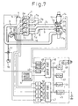
- reference number 1 illustrates an engine body
- reference numbers #1 - #4 illustrate first to fourth cylinders formed in the engine body 1, respectively.
- the first to fourth cylinders are arranged in line. Therefore, the first and fourth cylinders correspond to the outermost cylinders, and the second and third cylinders correspond to the middle cylinders located between the outermost cylinders.
- Reference numbers 2a - 2d illustrate first to fourth fuel injectors, respectively for injecting fuel into the corresponding cylinders #1 - #4 to drive the engine and purify an exhaust gas discharged from the engine as described below
- reference number 3 illustrates an intake passage
- reference number 4 illustrates an intake manifold connected to the intake passage 3.
- First to fourth exhaust branch passages 7a - 7d are respectively connected to each of the first to fourth cylinders #1 - #4.
- the first, second and fourth exhaust branch passages 7a, 7b and 7d are connected to each other and collected into a collection pipe 9 at an upstream connecting portion 8 which is downstream of the engine body 1.
- the words “upstream” and “downstream” are to indicate the flow of the exhaust gas.
- the first, second and fourth exhaust branch passages are connected to an upstream end of the common exhaust passage
- the third exhaust branch passage is connected to the common exhaust passage downstream of the upstream end of the common exhaust passage.
- the intake and exhaust side turbine wheels 11a and 11b are connected to each other by a common shaft 11c.
- An upstream temperature sensor 13 for detecting the temperature of the upstream end of the NOx catalyst 12 is positioned in the upstream end of the NOx catalyst 12.
- a downstream temperature sensor 14 for detecting the temperature of the downstream end of the NOx catalyst 12 is positioned in the downstream end of the NOx catalyst 12.
- An exhaust gas recirculation passage 15 for introducing the exhaust gas into the intake air is connected to the fourth exhaust branch passage 7d.
- the exhaust gas recirculation passage 15 is connected to the fourth exhaust branch passage 7d at a position such that the exhaust gas discharged from the third cylinder does not arrive at the exhaust gas recirculation passage 15 via the collection pipe 9 and the fourth exhaust branch passage 7d.
- the other end of the exhaust gas recirculation passage 15 is connected to the intake manifold 4.
- an inert gas decreases the velocity at which the flame is transmitted. Therefore, when the amount of the inert gas in the intake air is large, the velocity at which the flame is transmitted in the cylinders during the power stroke of the engine is decreased.
- the collection pipe 9 is connected to the third exhaust branch passage 7c in parallel with each other in such a manner that the exhaust gas discharged from the collection pipe 9 and the third exhaust branch passage 7c flows along the rotating surface of the exhaust side turbine wheel 11b.
- the exhaust gas is discharged from the collection pipe 9 and the third exhaust branch passage 7c at the downstream collection portion 10 toward the exhaust side turbine wheel 11b in the direction parallel to the rotating surface of the exhaust side turbine wheel 11b and perpendicular to the axis of the shaft 11c of the turbo-charger 11.
- the relationship between the cross sectional areas of the collection pipe 9 and the third exhaust branch passage 7c at the downstream collection portion 10 is 3:1, i.e., the ratio of the cross sectional area of the third exhaust branch passage 7c at which the third exhaust branch passage 7c is connected to the collection pipe 9 to the cross sectional area of the collection pipe 9 at which the collection pipe 9 is connected to the third exhaust branch passage 7c is 1:3. Since the cross sectional area of the third exhaust branch passage 7c is smaller than that of the collection pipe 9, the velocity of the exhaust gas discharged from the third exhaust branch passage 7c is increased. Therefore, it is ensured that the exhaust gas is discharged from the third exhaust branch passage 7c toward the exhaust side turbine wheel 11b. Thus, according to the first embodiment, it is ensured that the flow of the exhaust gas from the third exhaust branch passage 7c into the collection pipe 9 is prevented, and as a result, the introduction of the HC included in the exhaust gas into the intake air is prevented.
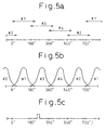
- the exhaust strokes are carried, out sequentially in the first #1, third #3, fourth #4 and second #2 cylinders. Further, when the exhaust strokes in the cylinders #1 - #4 are carried out, the exhaust valves 26 are open during crank angles larger than 180 degrees.
- HC for purifying the exhaust gas is injected into the third cylinder #3 during the exhaust stroke in the third cylinder #3 and, in addition, HC for driving the engine is injected into the third cylinder #3 during the compression stroke.
- the HC for purifying the exhaust gas may be injected into the third cylinder #3 during the power or exhaust stroke which is carried out after the HC for driving the engine is injected into the third cylinder #3.
- a HC injector positioned in the third exhaust branch passage as means for feeding a reducing agent may be used. Further, the size of the opening of the collection pipe at the downstream collection portion may be decreased in order to increase the pressure in the collection pipe to prevent the flow of the exhaust gas from the third exhaust branch passage into the collection pipe.
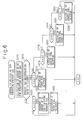
- the predetermined crank angle A2 is the angle which is in the power or exhaust stroke in the second cylinder #2 and at which the HC for purifying the exhaust gas should be injected from the second fuel injector 2b into the second cylinder #2.
- a ⁇ A2 the routine proceeds to step 222.
- the predetermined crank angle A3 is the angle which is in the power or exhaust stroke in the third cylinder #3 and at which the HC for purifying the exhaust gas should be injected from the third fuel injector 2c into the third cylinder #3.
- a ⁇ A3 the routine proceeds to step 226.
- the third exhaust branch passage 7c and the collection pipe 9 extend to enclose the exhaust side turbine wheel 11b.
- a part of the third exhaust branch passage 7c and a part of the collection pipe 9 are open to the exhaust side turbine wheel 11b.
- the third exhaust branch passage 7c and the collection pipe 9 are divided by a separating wall 19 around the exhaust side turbine wheel 11b.
- the relationship between the cross sectional size such as the cross sectional areas of the collection pipe 9 and the third exhaust branch passage 7c at the downstream collection portion 10 is 3:1 to 1:1.
- the ratio of the cross sectional size of the third exhaust branch passage 7c to that of the collection pipe 9 is from 1:3 to 1:1.
- the third embodiment compared with the first embodiment, it is further ensured that the exhaust gas is discharged from the third exhaust branch passage 7c toward the exhaust side turbine wheel 7c. Therefore, compared with the first embodiment, it is further ensured that the flow of the exhaust gas from the third exhaust branch passage 7c into the collection pipe 9 is prevented, and the introduction of the HC for purifying the exhaust gas into the intake air is prevented.
- an exhaust gas purification device for purifying an exhaust gas discharged from an engine having cylinders including first and second cylinders. An exhaust stroke in the first cylinder is carried out next to an exhaust stroke in the second cylinder.
- the exhaust gas purification device comprises exhaust branch passages which are connected to the cylinders, respectively.
- the exhaust branch passages include first and second exhaust branch passages which are connected to the first and second cylinders, respectively.
- the exhaust gas purification device comprises a common exhaust passage connected to the exhaust branch passages, a catalyst positioned in the common exhaust passage for purifying an exhaust gas, and an exhaust gas recirculation passage connected to the first exhaust branch passage.
- the exhaust gas recirculation passage introduces the exhaust gas from the first exhaust branch passage into an intake passage which is connected to the cylinders.
- a reducing agent is fed to only the second cylinder during the power or the exhaust stroke in the second cylinder to promote the purifying operation of the catalyst when the exhaust gas is introduced into the intake passage via the exhaust gas recirculation passage.
Landscapes
- Engineering & Computer Science (AREA)
- Chemical & Material Sciences (AREA)
- Combustion & Propulsion (AREA)
- Mechanical Engineering (AREA)
- General Engineering & Computer Science (AREA)
- Biomedical Technology (AREA)
- Health & Medical Sciences (AREA)
- Environmental & Geological Engineering (AREA)
- Analytical Chemistry (AREA)
- General Chemical & Material Sciences (AREA)
- Oil, Petroleum & Natural Gas (AREA)
- Chemical Kinetics & Catalysis (AREA)
- Exhaust Gas After Treatment (AREA)
Applications Claiming Priority (6)
| Application Number | Priority Date | Filing Date | Title |
|---|---|---|---|
| JP9162956A JPH1113552A (ja) | 1997-06-19 | 1997-06-19 | 過給機と排気循環装置とを備えた内燃機関の排気浄化装置 |
| JP16295697 | 1997-06-19 | ||
| JP162956/97 | 1997-06-19 | ||
| JP17844397 | 1997-07-03 | ||
| JP178443/97 | 1997-07-03 | ||
| JP17844397A JP3159131B2 (ja) | 1997-07-03 | 1997-07-03 | 排気循環装置を備えた排気浄化装置 |
Publications (2)
| Publication Number | Publication Date |
|---|---|
| EP0886044A1 true EP0886044A1 (de) | 1998-12-23 |
| EP0886044B1 EP0886044B1 (de) | 2002-03-20 |
Family
ID=26488564
Family Applications (1)
| Application Number | Title | Priority Date | Filing Date |
|---|---|---|---|
| EP98111244A Expired - Lifetime EP0886044B1 (de) | 1997-06-19 | 1998-06-18 | Abgasreinigungsvorrichtung |
Country Status (3)
| Country | Link |
|---|---|
| US (1) | US5987884A (de) |
| EP (1) | EP0886044B1 (de) |
| DE (1) | DE69804269T2 (de) |
Cited By (5)
| Publication number | Priority date | Publication date | Assignee | Title |
|---|---|---|---|---|
| WO2000032913A1 (de) * | 1998-12-01 | 2000-06-08 | Robert Bosch Gmbh | Vorrichtung zum nachbehandeln von abgasen einer brennkraftmaschine |
| FR2793522A1 (fr) | 1999-05-10 | 2000-11-17 | Univ Abdelmalek Essaadi | Dispositif pour pieger les matieres ou produits polluants emis par les fumees d'echappement d'un moteur fonctionnant avec un carburant |
| EP1744023A3 (de) * | 2005-07-15 | 2009-03-18 | Kabushiki Kaisha Toyota Jidoshokki | Kraftstoffversorgungssystem und Verfahren zur Kraftstoffversorgung einer Katalysatoranlage in einer Brennkraftmaschine |
| AT14291U1 (de) * | 2014-04-07 | 2015-07-15 | Avl List Gmbh | Brennkraftmaschine mit einem Einlasssystem und einem Auslasssystem |
| CN106870214A (zh) * | 2017-01-06 | 2017-06-20 | 中国第汽车股份有限公司 | 一种双流道涡轮增压器 |
Families Citing this family (20)
| Publication number | Priority date | Publication date | Assignee | Title |
|---|---|---|---|---|
| DE19747671C1 (de) * | 1997-10-29 | 1999-07-08 | Daimler Chrysler Ag | Verfahren zum Betrieb eines mehrzylindrigen Verbrennungsmotors |
| US6240721B1 (en) * | 1998-09-17 | 2001-06-05 | Toyota Jidosha Kabushiki Kaisha | Internal combustion engine and method for controlling an internal combustion engine |
| US6138650A (en) * | 1999-04-06 | 2000-10-31 | Caterpillar Inc. | Method of controlling fuel injectors for improved exhaust gas recirculation |
| US6244043B1 (en) * | 1999-05-19 | 2001-06-12 | Ford Global Technologies, Inc. | Emission control device air/fuel ratio control system |
| US6347619B1 (en) * | 2000-03-29 | 2002-02-19 | Deere & Company | Exhaust gas recirculation system for a turbocharged engine |
| DE10217589B4 (de) * | 2002-04-19 | 2005-06-09 | Siemens Ag | Verfahren zum Aufheizen eines Katalysators im Abgastrakt einer Brennkraftmaschine |
| US7104048B2 (en) * | 2004-04-30 | 2006-09-12 | General Motors Corporation | Low emission diesel particulate filter (DPF) regeneration |
| JP4462282B2 (ja) * | 2007-03-14 | 2010-05-12 | トヨタ自動車株式会社 | 内燃機関の排気制御装置 |
| JP4894877B2 (ja) * | 2009-03-26 | 2012-03-14 | マツダ株式会社 | 過給機付きエンジン |
| JP2013113217A (ja) * | 2011-11-29 | 2013-06-10 | Suzuki Motor Corp | 車両のegr流路未燃堆積物除去装置 |
| US8943822B2 (en) * | 2012-02-28 | 2015-02-03 | Electro-Motive Diesel, Inc. | Engine system having dedicated auxiliary connection to cylinder |
| JP6301845B2 (ja) | 2012-03-14 | 2018-03-28 | ボルボ ラストバグナー アーベー | 排ガスを未燃炭化水素でリッチ化する方法 |
| US8935917B2 (en) * | 2013-01-28 | 2015-01-20 | GM Global Technology Operations LLC | Partially integrated exhaust manifold |
| US20140373528A1 (en) * | 2013-06-20 | 2014-12-25 | Paccar Inc | Fixed positive displacement egr system |
| US9410504B2 (en) * | 2013-06-20 | 2016-08-09 | Paccar Inc | Mixer for pulsed EGR |
| DE102014203015A1 (de) * | 2014-02-19 | 2015-08-20 | Volkswagen Aktiengesellschaft | Verfahren und Vorrichtung zum Führen eines Abgasstroms eines Verbrennungsmotors mit einem lastabhängigen Wärmeübergangskoeffizienten |
| CN104863695B (zh) * | 2014-02-21 | 2020-01-31 | 康明斯有限公司 | 优化发动机性能以高扭矩运行的装置、方法和系统 |
| GB2529133B (en) * | 2014-05-30 | 2020-08-05 | Cummins Inc | Engine systems and methods for operating an engine |
| US11199162B2 (en) | 2016-01-19 | 2021-12-14 | Eaton Intelligent Power Limited | In-cylinder EGR and VVA for aftertreatment temperature control |
| DE112017000256T5 (de) * | 2016-01-19 | 2018-09-27 | Eaton Intelligent Power Limited | Luftstrommanagementstrategien für einen Dieselmotor |
Citations (5)
| Publication number | Priority date | Publication date | Assignee | Title |
|---|---|---|---|---|
| US4056933A (en) * | 1976-01-09 | 1977-11-08 | Toyota Jidosha Kogyo Kabushiki Kaisha | Exhaust gas purifier in an internal combustion engine |
| US4179892A (en) * | 1977-12-27 | 1979-12-25 | Cummins Engine Company, Inc. | Internal combustion engine with exhaust gas recirculation |
| JPH0674022A (ja) | 1992-08-26 | 1994-03-15 | Isuzu Motors Ltd | 内燃機関の排気ガス浄化装置 |
| DE4421258A1 (de) * | 1994-06-17 | 1995-12-21 | Bayerische Motoren Werke Ag | Brennkraftmaschine mit Zylinderabschaltung und zumindest einem Abgaskatalysator |
| EP0838582A1 (de) * | 1996-10-28 | 1998-04-29 | Institut Francais Du Petrole | Verfahren zur Steuerung des Einlasses einer Viertaktbrennkraftmaschine mit Direkteinspritzung |
Family Cites Families (4)
| Publication number | Priority date | Publication date | Assignee | Title |
|---|---|---|---|---|
| JPH0681631A (ja) * | 1992-08-28 | 1994-03-22 | Isuzu Motors Ltd | 内燃機関の排気ガス浄化装置 |
| US5803048A (en) * | 1994-04-08 | 1998-09-08 | Honda Giken Kogyo Kabushiki Kaisha | System and method for controlling air-fuel ratio in internal combustion engine |
| JPH0996256A (ja) * | 1995-10-03 | 1997-04-08 | Nippon Soken Inc | Egrガスアシスト噴射システム |
| JP3465490B2 (ja) * | 1996-09-09 | 2003-11-10 | トヨタ自動車株式会社 | 内燃機関の排気浄化装置 |
-
1998
- 1998-06-11 US US09/095,763 patent/US5987884A/en not_active Expired - Fee Related
- 1998-06-18 DE DE69804269T patent/DE69804269T2/de not_active Expired - Fee Related
- 1998-06-18 EP EP98111244A patent/EP0886044B1/de not_active Expired - Lifetime
Patent Citations (5)
| Publication number | Priority date | Publication date | Assignee | Title |
|---|---|---|---|---|
| US4056933A (en) * | 1976-01-09 | 1977-11-08 | Toyota Jidosha Kogyo Kabushiki Kaisha | Exhaust gas purifier in an internal combustion engine |
| US4179892A (en) * | 1977-12-27 | 1979-12-25 | Cummins Engine Company, Inc. | Internal combustion engine with exhaust gas recirculation |
| JPH0674022A (ja) | 1992-08-26 | 1994-03-15 | Isuzu Motors Ltd | 内燃機関の排気ガス浄化装置 |
| DE4421258A1 (de) * | 1994-06-17 | 1995-12-21 | Bayerische Motoren Werke Ag | Brennkraftmaschine mit Zylinderabschaltung und zumindest einem Abgaskatalysator |
| EP0838582A1 (de) * | 1996-10-28 | 1998-04-29 | Institut Francais Du Petrole | Verfahren zur Steuerung des Einlasses einer Viertaktbrennkraftmaschine mit Direkteinspritzung |
Non-Patent Citations (1)
| Title |
|---|
| PATENT ABSTRACTS OF JAPAN vol. 018, no. 323 (M - 1624) 20 June 1994 (1994-06-20) * |
Cited By (8)
| Publication number | Priority date | Publication date | Assignee | Title |
|---|---|---|---|---|
| WO2000032913A1 (de) * | 1998-12-01 | 2000-06-08 | Robert Bosch Gmbh | Vorrichtung zum nachbehandeln von abgasen einer brennkraftmaschine |
| US6843966B1 (en) | 1998-12-01 | 2005-01-18 | Robert Bosch Gmbh | Apparatus for post-treating exhaust gases of an internal combustion engine |
| FR2793522A1 (fr) | 1999-05-10 | 2000-11-17 | Univ Abdelmalek Essaadi | Dispositif pour pieger les matieres ou produits polluants emis par les fumees d'echappement d'un moteur fonctionnant avec un carburant |
| EP1744023A3 (de) * | 2005-07-15 | 2009-03-18 | Kabushiki Kaisha Toyota Jidoshokki | Kraftstoffversorgungssystem und Verfahren zur Kraftstoffversorgung einer Katalysatoranlage in einer Brennkraftmaschine |
| US7540146B2 (en) | 2005-07-15 | 2009-06-02 | Kabushiki Kaisha Toyotal Jidoshokki | Fuel supply system and fuel supply method for exhaust purifying catalyst device in internal combustion engine |
| AT14291U1 (de) * | 2014-04-07 | 2015-07-15 | Avl List Gmbh | Brennkraftmaschine mit einem Einlasssystem und einem Auslasssystem |
| CN106870214A (zh) * | 2017-01-06 | 2017-06-20 | 中国第汽车股份有限公司 | 一种双流道涡轮增压器 |
| CN106870214B (zh) * | 2017-01-06 | 2020-05-22 | 中国第一汽车股份有限公司 | 一种双流道涡轮增压器 |
Also Published As
| Publication number | Publication date |
|---|---|
| US5987884A (en) | 1999-11-23 |
| DE69804269T2 (de) | 2002-08-08 |
| EP0886044B1 (de) | 2002-03-20 |
| DE69804269D1 (de) | 2002-04-25 |
Similar Documents
| Publication | Publication Date | Title |
|---|---|---|
| EP0886044B1 (de) | Abgasreinigungsvorrichtung | |
| EP0889220B1 (de) | Brennstoffeinspritzvorrichtung für eine Brennkraftmaschine | |
| EP0957254B1 (de) | Vorrichtung zur Abgasreinigung für eine Brennkraftmaschine | |
| US6276138B1 (en) | Engine with direct turbo compounding | |
| US6948310B2 (en) | Use of a variable valve actuation system to control the exhaust gas temperature and space velocity of aftertreatment system feedgas | |
| US6941755B2 (en) | Integrated bypass and variable geometry configuration for an exhaust gas turbocharger | |
| EP2256311B1 (de) | Abgasreiniger für einen verbrennungsmotor | |
| US7299623B2 (en) | Method for controlling exhaust gas temperature and space velocity during regeneration to protect temperature sensitive diesel engine components and aftertreatment devices | |
| US20120216529A1 (en) | Engine exhaust aftertreatment system | |
| JP2002508472A (ja) | 燃焼機関のための装置 | |
| EP2071144B1 (de) | Verbrennungskraftmaschine | |
| JP2005291090A (ja) | 内燃機関における排気ガス浄化装置 | |
| EP0829630B1 (de) | Vorrichtung zur Steuerung einer Brennkraftmaschine | |
| JP2010031718A (ja) | 排気浄化装置 | |
| US7338642B2 (en) | Exhaust gas purification device for engine | |
| EP0838579A2 (de) | Abgasreinigungsvorrichtung für einen Motor | |
| US11300065B2 (en) | Method of controlling temperature of exhaust purification device of internal combustion engine, and internal combustion engine control device | |
| EP2264291B1 (de) | Abgasreinigungssystem für verbrennungsmotor | |
| JP2006200473A (ja) | 排ガス後処理装置付きエンジンの制御装置 | |
| JP2007239493A (ja) | 過給機付き内燃機関 | |
| EP1799978B1 (de) | Abgasreinigungssystem für einen verbrennungsmotor und abgasreinigungsverfahren | |
| JPH11173138A (ja) | 内燃機関の排気浄化装置 | |
| JP3159131B2 (ja) | 排気循環装置を備えた排気浄化装置 | |
| JP3287273B2 (ja) | 排気循環装置を備えた排気浄化装置 | |
| JP4983144B2 (ja) | Egr装置を備えた内燃機関 |
Legal Events
| Date | Code | Title | Description |
|---|---|---|---|
| PUAI | Public reference made under article 153(3) epc to a published international application that has entered the european phase |
Free format text: ORIGINAL CODE: 0009012 |
|
| 17P | Request for examination filed |
Effective date: 19980618 |
|
| AK | Designated contracting states |
Kind code of ref document: A1 Designated state(s): DE FR GB |
|
| AX | Request for extension of the european patent |
Free format text: AL;LT;LV;MK;RO;SI |
|
| AKX | Designation fees paid |
Free format text: DE FR GB |
|
| GRAG | Despatch of communication of intention to grant |
Free format text: ORIGINAL CODE: EPIDOS AGRA |
|
| 17Q | First examination report despatched |
Effective date: 20010516 |
|
| GRAG | Despatch of communication of intention to grant |
Free format text: ORIGINAL CODE: EPIDOS AGRA |
|
| GRAG | Despatch of communication of intention to grant |
Free format text: ORIGINAL CODE: EPIDOS AGRA |
|
| GRAH | Despatch of communication of intention to grant a patent |
Free format text: ORIGINAL CODE: EPIDOS IGRA |
|
| GRAH | Despatch of communication of intention to grant a patent |
Free format text: ORIGINAL CODE: EPIDOS IGRA |
|
| REG | Reference to a national code |
Ref country code: GB Ref legal event code: IF02 |
|
| GRAA | (expected) grant |
Free format text: ORIGINAL CODE: 0009210 |
|
| AK | Designated contracting states |
Kind code of ref document: B1 Designated state(s): DE FR GB |
|
| REF | Corresponds to: |
Ref document number: 69804269 Country of ref document: DE Date of ref document: 20020425 |
|
| ET | Fr: translation filed | ||
| PLBE | No opposition filed within time limit |
Free format text: ORIGINAL CODE: 0009261 |
|
| 26N | No opposition filed |
Effective date: 20021223 |
|
| PGFP | Annual fee paid to national office [announced via postgrant information from national office to epo] |
Ref country code: FR Payment date: 20050608 Year of fee payment: 8 |
|
| PGFP | Annual fee paid to national office [announced via postgrant information from national office to epo] |
Ref country code: GB Payment date: 20050615 Year of fee payment: 8 |
|
| PGFP | Annual fee paid to national office [announced via postgrant information from national office to epo] |
Ref country code: DE Payment date: 20050616 Year of fee payment: 8 |
|
| PG25 | Lapsed in a contracting state [announced via postgrant information from national office to epo] |
Ref country code: GB Free format text: LAPSE BECAUSE OF NON-PAYMENT OF DUE FEES Effective date: 20060618 |
|
| PG25 | Lapsed in a contracting state [announced via postgrant information from national office to epo] |
Ref country code: DE Free format text: LAPSE BECAUSE OF NON-PAYMENT OF DUE FEES Effective date: 20070103 |
|
| GBPC | Gb: european patent ceased through non-payment of renewal fee |
Effective date: 20060618 |
|
| REG | Reference to a national code |
Ref country code: FR Ref legal event code: ST Effective date: 20070228 |
|
| PG25 | Lapsed in a contracting state [announced via postgrant information from national office to epo] |
Ref country code: FR Free format text: LAPSE BECAUSE OF NON-PAYMENT OF DUE FEES Effective date: 20060630 |