EP0887508B1 - Store vénitien avec rail supérieur déplaçable - Google Patents
Store vénitien avec rail supérieur déplaçable Download PDFInfo
- Publication number
- EP0887508B1 EP0887508B1 EP98111686A EP98111686A EP0887508B1 EP 0887508 B1 EP0887508 B1 EP 0887508B1 EP 98111686 A EP98111686 A EP 98111686A EP 98111686 A EP98111686 A EP 98111686A EP 0887508 B1 EP0887508 B1 EP 0887508B1
- Authority
- EP
- European Patent Office
- Prior art keywords
- motor
- sunshade device
- rail
- tilting
- bar
- Prior art date
- Legal status (The legal status is an assumption and is not a legal conclusion. Google has not performed a legal analysis and makes no representation as to the accuracy of the status listed.)
- Expired - Lifetime
Links
- 230000037072 sun protection Effects 0.000 abstract description 36
- 238000009434 installation Methods 0.000 abstract description 4
- 230000002441 reversible effect Effects 0.000 description 15
- 230000008901 benefit Effects 0.000 description 3
- 230000008878 coupling Effects 0.000 description 3
- 238000010168 coupling process Methods 0.000 description 3
- 238000005859 coupling reaction Methods 0.000 description 3
- 238000010276 construction Methods 0.000 description 2
- 241000446313 Lamella Species 0.000 description 1
- 230000008859 change Effects 0.000 description 1
- 238000011109 contamination Methods 0.000 description 1
- 230000005611 electricity Effects 0.000 description 1
- 238000009413 insulation Methods 0.000 description 1
- 230000007246 mechanism Effects 0.000 description 1
- 239000002184 metal Substances 0.000 description 1
- 230000004048 modification Effects 0.000 description 1
- 238000012986 modification Methods 0.000 description 1
- 230000002028 premature Effects 0.000 description 1
- 239000004753 textile Substances 0.000 description 1
- 230000001960 triggered effect Effects 0.000 description 1
- XLYOFNOQVPJJNP-UHFFFAOYSA-N water Substances O XLYOFNOQVPJJNP-UHFFFAOYSA-N 0.000 description 1
- 238000004804 winding Methods 0.000 description 1
Images


Classifications
-
- E—FIXED CONSTRUCTIONS
- E06—DOORS, WINDOWS, SHUTTERS, OR ROLLER BLINDS IN GENERAL; LADDERS
- E06B—FIXED OR MOVABLE CLOSURES FOR OPENINGS IN BUILDINGS, VEHICLES, FENCES OR LIKE ENCLOSURES IN GENERAL, e.g. DOORS, WINDOWS, BLINDS, GATES
- E06B9/00—Screening or protective devices for wall or similar openings, with or without operating or securing mechanisms; Closures of similar construction
- E06B9/24—Screens or other constructions affording protection against light, especially against sunshine; Similar screens for privacy or appearance; Slat blinds
- E06B9/26—Lamellar or like blinds, e.g. venetian blinds
- E06B9/28—Lamellar or like blinds, e.g. venetian blinds with horizontal lamellae, e.g. non-liftable
- E06B9/30—Lamellar or like blinds, e.g. venetian blinds with horizontal lamellae, e.g. non-liftable liftable
- E06B9/32—Operating, guiding, or securing devices therefor
- E06B9/327—Guides for raisable lamellar blinds with horizontal lamellae
Definitions
- the invention relates to a sun protection system when retracted into a package gathered horizontal Slats on a turning device to adjust their inclination hanging on one with the help of elevator elements movable reversible rail is mounted.
- Sun protection systems with horizontal slats - also venetian blinds called - usually work according to the same system.
- the slats are on both sides by a kind of ladder forming support elements, usually cords, or one Loop cord held over which the slat curtain attaches a turning device often integrated in a housing hangs.
- a bottom rail is used to retract the curtain pulled up by elevator elements, with the slats one after the other on this lower rail to form a package stack.
- a venetian blind is already known from US Pat. No. 5,443,108, its turning rail together with a turning device mounted on it can be moved by elevator elements. Disadvantageous with this construction is that the manual drive the turning device only installation on one Inside of the window allowed and no automatic setting the slat inclination, such as for the Use in office buildings is essential to be realized can. This allows the advantage of a movable reversing rail, that in reducing the space required is above the window area, only very limited deploy.
- the object of the invention is a sun protection system to create that has a movable reversible rail and is universally applicable.
- the task is performed by a sun protection system of the type described above, in which in an electric motor is provided on the turning rail, which at least drives the turning device and the one to a supply source in the reversing rail or over free hanging or windable supply lines or via sliding contacts, that run on side tracks, to one external supply source is connected.
- the arrangement of the drive motor in the reversing rail allows a remote control for the control of the slat inclination for example from the interior of the room, so that the sun protection system easily mounted on the outside of windows can be.
- the problem of powering an electric motor according to the invention in the movable turning rail solved by one of the proposed variants.
- a motor drives in the turning rail on the elevator elements.
- a housing for the window area to be shaded that receives the drive motor for the elevator elements.
- the lowest slat is usually above support elements connected with a bottom rail. This can be below the surface to be shaded or fixed Help from catch-up elements mounted on the reversing rail be windable with a motor.
- the slat curtain below the window area to be shaded In the variant with fixed assembled bottom rail is gathered together the slat curtain below the window area to be shaded.
- the second variant with regardless of the Reversible lower rail can be the shirring of the Package at any desired location in the travel area of the two rails. This variant enables very variable shading of the window surface, so that e.g. also a cutout in the middle of the window area can be shaded.
- a single motor drives the turning device, the elevator elements and / or the catch-up elements accomplished.
- the distribution of the drive torque the motor to the individual elements can be switched Couplings, slip clutches, freewheels or the like.
- it is easily possible instead of one Motor in the reversing rail for driving the elevator elements or catch-up elements usual constructions with fixed built-in elevator motors or manual elevator devices with the motor-driven according to the invention Turning mechanism in the movable turning rail combine.
- the control of the at least one electric motor in the Reversible rail is preferably a cordless Signal receiver from the supply source of the motor is fed with.
- the wireless control of the electric motors avoids additional control cables and offers different ones Possibilities of manual or automatic Control.
- the drive of the turning bearings of the turning device and the Elevator rolls of the elevator elements are of a kind and Way, as from the usual combined turning and pull-out drives for sun protection systems with overhead Slat package is known.
- the drive motor takes the turning bearings and thus the Support elements on which the slats are suspended, only over a certain angle of rotation up to a stop.
- a slip clutch ensures for the fact that the elevator rollers, despite the blocked
- the turning bearing can continue to rotate, so that the lamella curtain can be retracted or extended.
- the catch-up elements to the drive motor be coupled in the turning rail, for example the drive torque of the motor optionally on the elevator elements or the catch-up elements works.
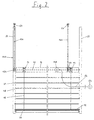
- Fig. 1 shows a first embodiment of a sun protection system 10. A cross section of this sun protection system is in Fig. 5 shown.
- the sun protection system 10 has a turning rail 12 with Spiral bearings 14, which carry supporting elements 16 guided over them.
- the actual curtain of the sun protection system 10 is formed by lamellae 18, each over their support elements 16 running past both longitudinal sides in a certain Hang the distance to the adjacent slats 18.
- the turning rail 12 has lateral guide bolts 20, with the help of which they are in lateral guide rails 22 is guided flexibly.
- the slats 18 have alternately Guide bolts 24 on their left and right sides. Alternatively for this it would be conceivable not to have all the lamellae 18 Guide bolts 24, some with guide bolts on both sides 24 to be provided.
- the turning rail 12 is suspended from elevator elements 26, e.g. on the guide pin 20 (see left half of Fig. 1) or in a central attachment point 28 (see Fig. 5) can be attached to the housing 30 of the turning rail 12.
- the elevator elements 26 are above by deflecting rollers 32 deflected the travel range of the turning rail 12 and are connected to elevator rollers 34 below the slats 18.
- the two elevator rollers 34 are driven by a drive shaft 36 driven by a motor 38.
- the elevator elements 26 can be tapes made of textiles, perforated plastic or metal, but also chains.
- the turning rail 12 also takes one Reversible motor 40, the reversible bearing via a drive shaft 42 14 drives a supply source 44 for the Power supply to the turning motor 40 and a signal receiving unit 46 on, with the aid of which the turning motor 40 is controlled can be.
- the supply source 44 can, for example be an accumulator connected via contacts (not shown) the reversible rail 12 is rechargeable, which is completely after below driven reversing rail 12 with live stationary contacts (not shown) are in contact.
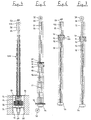
- the turning bearings 14 can a certain angle of rotation between two stop positions can be rotated (see Fig. 5 to 7).
- Fig. 5 shows in cross section a horizontal position of the Slats 18, in which the turning bearing 14 in one middle position between the two stop positions are located and the support members 16 on both long sides of the Slats 18 of the same length omitted from the reversing rail 12 are.
- Fig. 7 shows the reversible bearing 14 in its opposite Stop position in which the support elements in comparison omitted to the position of FIG. 6 in the reverse manner or caught up. Even with this position of the turning bearings 14 results in a closed curtain position of the slats 18, but with the inverted position of the individual slats 18.
- Fig. 7 also shows an alternative location of the Drive motor 38 above the guide rails 22.
- the deflection rollers 32 can be dispensed with at the same time, however, the space requirement increases because of the 22 between the two guide rails transverse drive shaft. This is usually common integrated with the motor 38 in a top rail, so that the space requirement in the upper area of the sun protection system 10 increases.
- the drive of the reversible bearing 14 could be shown in FIG. 1 Embodiment instead of a separate turning motor 40 also with the help of a drive shaft 42 seated gear (not shown) take place with a Rack cooperates in the side guide rail 22.
- the driving shaft 14 is carried along by the drive shaft 42 takes place when the turning rail 12 moves up or down then via a slip clutch or the like Change the direction of movement of the turning rail 12 that Takes the turning bearing up to its stop and thereby the Slats adjusted in their inclination. Will the turning rail 12 move further in this direction, the drive shaft 42 thanks to the slip clutch relative to the turning bearing 14 turn.
- the reversible bearings 14 via a slip clutch or the like acting elements coupled to the drive shaft 42.
- the drive shaft 42 continues to drive elevator rollers 134, to which elevator elements 126 when the reversing rail is raised 12 can be wound up. Hold the elevator elements 126 the turning rail 12 in its current position and are in relation to when moving the turning rail 12 are not moved onto the side guide rails 22, at attachment points 50 above the sun protection system 110 attached.
- the power supply of the combined drive and reversing motor 140 does not have one in the reversing rail 12 housed supply source but about a supply line 56 connected to a voltage source 54 connected.
- the signal receiver 46 can at such control of the motor 140 is eliminated.
- the supply line 56 can hang freely, resiliently or be designed to be windable on a winding roll.
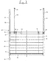
- FIG. 3 shows a further possibility of the engine 140 to supply with electricity.
- the rest of the structure corresponds the sun protection system 210 shown in FIG. 3 from Fig. 2.
- the Power supply via 22 extending in the side guide rails Busbars 58 (see also FIGS. 4 and 8) that connected at its lower end to a voltage source 60 are.
- the turning and elevator motor 140 is via supply lines 256 connected to sliding contacts 62, which with contact the busbars 58.
- the Sliding contacts 62 via spring elements 64, which they against the Press busbars 58.
- FIG. 1 represents two variants of the arrangement of the elevator elements.
- FIG. 8 shows the cross-sectional shape of the guide rail 22 evident. In cross section, it has three longitudinal chambers 68, 70 accessible from the outside through narrow slots 66 are, the middle chamber 68 the guide pin 20th of the reversing rail and the two outer chambers 70 each take up a busbar 58 and as a guideway serve for the sliding contacts 62. To only one if possible needing simple insulation of the busbars 58 works the reversible and elevator motor 140 preferably with low voltages.
- FIG. 4 shows - as an example - the sun protection system 210 in FIG fully retracted condition.
- the slats 18 rest a package 22 gathered on a lower rail 74 that on Mounting bracket 76 rests or over this the inner walls a shaft 78 is attached.
- the shaft 78 is closed by a cover 80 in the retracted state, attached to the top of the turning rail 12 is.
- the cover 80 in a shoulder 82 on the top of the shaft 78.
- the shaft 78 forms together with the Cover 80 a protection against the ingress of water and Dirt, which is particularly because of the arranged in the shaft 78 electrical components is particularly important, however also counteracts premature contamination of the slats 18.
- the turning rail 12 is in the half-extended Position shown, in which only a part of the slats 18 folded as a package rests on the lower rail 74.
- the illustration of shaft 78 was shown in this figure waived.
- FIGS. 6 and 7 show the turning rail 12 in the maximum extended position Position. All slats are in this position 18 lifted off the lower rail 74 and form one hanging curtain. The lowest slat 18 is on the lower rail 74, e.g. B. fixed on the support elements to the Stabilize the curtain additionally. Also an immediate one Attachment of the lowest slat 18 on the shaft 78 or the Building wall is conceivable.
- FIG. 9 is a modification of that shown in Fig. 3 Sun protection system 210 shown.
- This sun protection system 310 differs from that shown in FIG. 3 Sun protection system 210 in that the lower rail 374 not rigidly attached below the area to be shaded but movable in the side guide rails 22 is performed.
- To the bottom rail 374 regardless of the The sun protection system has the ability to move the reversing rail 12 310 via combined elevator / turning bracket 314, which is a raising of the curtain with the help of the motor 140 enable.
- the elevator rollers 134 with the help of which the Reversible rail is movable, correspond in their design the embodiment shown in Fig.
- the coupling to the motor 140 is preferably carried out via a switchable coupling to either the reversing rail 12 or move the lower rail 374 in the guide rails 22 to be able to.
- the power supply to the motor 140 corresponds the embodiment shown in FIG. 3.
- Fig. 9 allows a flexible Shading of the window surface because the curtain is gathered 72 at any desired point in the travel range can.
- the limit switch for each for opening and closing the reversible rail 12 responsible motor 38, 140 can by Switch sensors attached to the motor or separately positioned Limit switches are made directly by the turning rail 12 are started and triggered. Basically are all previously known variants of a limit switch also to the sun protection systems 10 described here, 110, 210 transferable.
- the control of the motors can be done in the presence a signal receiver 46 by wireless infrared or Radio signal transmitters take place, or, in the case of fixed supply lines or busbars, via ordinary switches.
- sun protection systems all have the advantage that unlike usual Sun protection systems above the window area to be shaded little or no installation space required is.
Landscapes
- Engineering & Computer Science (AREA)
- Structural Engineering (AREA)
- Architecture (AREA)
- Civil Engineering (AREA)
- Blinds (AREA)
- Operating, Guiding And Securing Of Roll- Type Closing Members (AREA)
- Power-Operated Mechanisms For Wings (AREA)
- Types And Forms Of Lifts (AREA)
Claims (10)
- Un élément de protection solaire qui consiste dans un remonté en un bloc (72) de lames (18) horizontales, serrées et qui sont fixées à un dispositif tournant (14 ; 16 ; 42) par rapport à leur réglage d'orientation, celui -ci étant monté sur une tige d'orientation déplaçable (12) au moyen de mécanismes de manoeuvre (26 ; 126), est caractérisé par le fait qu'un moteur électrique (40 ; 140), qui doit au moins assurer l'entraínement du dispositif tournant (14 ; 16 ; 42) et qui est connecté à une source d'alimentation (44) dans la tige d'orientation (12) ou à une source d'alimentation externe (54 ; 60) par des conduites d'alimentation suspendues librement ou à enrouler (56) ou par des contacts en boucle (62) glissés sur les rails conducteurs latéraux (58), a été prévu dans la tige d'orientation (12).
- Un élément de protection solaire selon la revendication 1, est caractérisé par le fait qu'un moteur (140) dans la tige d'orientation (12) assure l'entraínement des mécanismes de manoeuvre (26 ; 126).
- Un élément de protection solaire selon la revendication 1 ou 2, est caractérisé par le fait que la lame inférieure est fixée à un rail inférieur (74 ; 374) au moyen d'éléments - porteur (16), ce rail étant arrêté en dessous de la surface à protéger du soleil ou qui peut être remontée au moyen d'un dispositif de remontage (314) fixé sur la tige d'orientation (12) grâce à un moteur (140).
- Un élément de protection solaire selon l'une des revendications 1 à 3 est caractérisé par le fait qu'un seul moteur (140) assure l'entraínement du dispositif tournant (14 ; 16 ; 42), des mécanismes de manoeuvre (26 ; 126) et/ou des dispositifs de remontage (314).
- Un élément de protection solaire selon la revendication 4 est caractérisé par le fait que la répartition du couple d'entraínement du moteur (140) aux éléments isolés (14 ; 16 ; 42 ; 26 ; 126 ; 314) s'effectue par des couplages manoeuvrables, des accouplements à friction ou des moyeus à roue libre.
- Un élément de protection solaire selon l'une des revendications mentionnées ci-dessus, est caractérisé par le fait que les mécanismes de manoeuvre (26 ; 126) consistent en bandeaux, cordons, chaínettes, etc. ou en élements dentés sur la tige d'orientation (12) et en endentements coopérés, qui sont dispose en rails de guidage latéraux (22).
- Un élément de protection solaire selon l'une des revendications mentionnées ci-dessus, est caractérisé par le fait qu'au moins un moteur électrique (40) peut être manoeuvré par une commande à distance (46), celui-ci étant alimenté par les sources d'alimentation (44 ; 54 ; 60) du moteur (140).
- Un élément de protection solaire selon l'une des revendications mentionnées ci-dessus, est caractérisé par le fait que la source d'alimentation (44) consiste en un accumulateur qui peut être chargé au moyen de contacts sur la tige d'orientation qui, lorsque l'élément de protection solaire est rentré, est en contact avec une source de tension.
- Un élément de protection solaire selon l'une des revendications mentionnées ci-dessus, est caractérisé par le fait que la tension d'alimentation se trouve dans la zone à basse tension et que les mécanismes de manoeuvre (26 ; 126) servent de conduites d'alimentation.
- Un élément de protection solaire selon l'une des revendications mentionnées ci-dessus, est caractérisé par le fait que la tige d'orientation (12) peut être manoeuvrée vers le haut au moyen d'un axe à ressort fixé sur un rail supérieur et vers le bas au moyen d'un moteur à entraínement contraire à la force du ressort.
Applications Claiming Priority (2)
| Application Number | Priority Date | Filing Date | Title |
|---|---|---|---|
| DE19727379A DE19727379A1 (de) | 1997-06-27 | 1997-06-27 | Raffstore mit Wendeantrieb |
| DE19727379 | 1997-06-27 |
Publications (2)
| Publication Number | Publication Date |
|---|---|
| EP0887508A1 EP0887508A1 (fr) | 1998-12-30 |
| EP0887508B1 true EP0887508B1 (fr) | 2001-09-12 |
Family
ID=7833848
Family Applications (1)
| Application Number | Title | Priority Date | Filing Date |
|---|---|---|---|
| EP98111686A Expired - Lifetime EP0887508B1 (fr) | 1997-06-27 | 1998-06-25 | Store vénitien avec rail supérieur déplaçable |
Country Status (3)
| Country | Link |
|---|---|
| EP (1) | EP0887508B1 (fr) |
| AT (1) | ATE205577T1 (fr) |
| DE (2) | DE19727379A1 (fr) |
Families Citing this family (10)
| Publication number | Priority date | Publication date | Assignee | Title |
|---|---|---|---|---|
| DE19916365A1 (de) * | 1999-04-13 | 2000-10-26 | Alten Geraetebau Gmbh | Tor für Gebäude |
| DE29913131U1 (de) * | 1999-07-27 | 2000-12-07 | Hüppe Form Sonnenschutzsysteme GmbH, 26133 Oldenburg | Lamellenjalousie |
| CH699424B1 (de) * | 2000-12-07 | 2010-03-15 | Griesser Holding Ag | Lamellenstore mit Wendevorrichtung. |
| CH700254B1 (de) * | 2000-12-07 | 2010-07-30 | Griesser Holding Ag | Abdeckvorrichtung. |
| FR2869063B1 (fr) * | 2004-04-16 | 2008-04-04 | Franciaflex Ind Sa | Store venitien a mouvement inverse |
| FR2869064B1 (fr) * | 2004-04-16 | 2006-09-08 | Franciaflex Ind Sa | Store venitien a mouvement inverse |
| PL3181798T3 (pl) * | 2015-12-18 | 2019-05-31 | Vkr Holding As | Urządzenie zasłaniające do okna, sposób przesyłania sygnałów w urządzeniu zasłaniającym |
| DE102015122723A1 (de) | 2015-12-23 | 2017-06-29 | Heroal - Johann Henkenjohann Gmbh & Co. Kg | Sonnenschutzsystem |
| US11957261B2 (en) | 2017-04-28 | 2024-04-16 | Lutron Technology Company Llc | Window treatment mounting bracket |
| CN110219574B (zh) * | 2019-06-05 | 2024-07-26 | 佛山市欧玛斯建材有限公司 | 一种可内置百页窗帘的隔墙的改进结构 |
Family Cites Families (7)
| Publication number | Priority date | Publication date | Assignee | Title |
|---|---|---|---|---|
| DE1791377U (de) * | 1959-03-14 | 1959-07-02 | Fenestra Crittall Ag | Lamellen-sonnenstone, insbesondere fuer schaufenster od. dgl. |
| DE1683366B1 (de) * | 1967-01-23 | 1970-04-09 | Persson Bo S V | Raffbare Lamellenjalousie mit einer in der senkrechten Abschirmebene beweglichen Stelleiste |
| DE3801560A1 (de) * | 1988-01-20 | 1989-08-03 | Warema Renkhoff Gmbh & Co Kg | Betaetigungsvorrichtung fuer eine raffbare lamellenjalousie mit elektromotor |
| NL8802303A (nl) * | 1988-09-16 | 1990-04-17 | Schoen Siegfried Joachim | Elektro-motorisch aangedreven zonwering. |
| US5443108A (en) * | 1993-06-01 | 1995-08-22 | Levert; Francis E. | Upwardly deployed privacy blind |
| DE9406083U1 (de) * | 1994-04-13 | 1994-06-09 | syba Technik und Design am Fenster GmbH, 28329 Bremen | Elektrische Stellantriebseinheit für Vertikal-Lamellen |
| DE19531363A1 (de) * | 1995-08-25 | 1997-02-27 | Guenter Dipl Ing Lenze | Mit Zug- und Spannvorrichtungen ausgestattetes Abschirmsystem |
-
1997
- 1997-06-27 DE DE19727379A patent/DE19727379A1/de not_active Withdrawn
-
1998
- 1998-06-25 EP EP98111686A patent/EP0887508B1/fr not_active Expired - Lifetime
- 1998-06-25 AT AT98111686T patent/ATE205577T1/de not_active IP Right Cessation
- 1998-06-25 DE DE59801429T patent/DE59801429D1/de not_active Expired - Fee Related
Also Published As
| Publication number | Publication date |
|---|---|
| DE59801429D1 (de) | 2001-10-18 |
| ATE205577T1 (de) | 2001-09-15 |
| EP0887508A1 (fr) | 1998-12-30 |
| DE19727379A1 (de) | 1999-02-11 |
Similar Documents
| Publication | Publication Date | Title |
|---|---|---|
| EP1970235B1 (fr) | Store de fenêtre latérale doté d'un entraînement à corde | |
| EP1306251A1 (fr) | Store à enrouler divisé pour une fenêtre de véhicule | |
| EP1967401A2 (fr) | Store de fenêtre latérale actionné de manière automatique | |
| EP2060421A1 (fr) | Agencement de store doté d'un entraînement à friction réduite | |
| EP0887508B1 (fr) | Store vénitien avec rail supérieur déplaçable | |
| DE4230729A1 (de) | Vorrichtung zur antriebsabschaltung des motors elektrisch betriebener rollaeden, rolltore, markisen o. dgl. | |
| DE3345503A1 (de) | Rollo fuer fahrzeugscheiben | |
| EP0313809A1 (fr) | Volet roulant pour fenêtre de toiture | |
| DE3415551C2 (de) | Rolladen für Dachfenster | |
| DE8703605U1 (de) | Rollo für Automobilfenster, insbesondere für PKW-Heckscheiben | |
| DE69130796T2 (de) | Fensterjalousie oder vorhang, insbesondere für zweischeibenisolationsglasfenster | |
| EP0989279A2 (fr) | Jalousie dans vitrage isolant | |
| EP2006133A2 (fr) | Store électrique pour fenêtre latérale | |
| DE69600625T2 (de) | Doppelte abschirmvorrichtung für ein fenster | |
| AT410241B (de) | Rolladen | |
| EP0989006A1 (fr) | Store de fenêtre à commande électromécanique, en particulier pour véhicules automobiles | |
| DE3115926C2 (de) | Rolladen für Dachfenster in Schwenkflügelbauweise | |
| EP0534894A1 (fr) | Dispositif pour une déconnexion d'entraînement d'un moteur de volets roulants, de portes à rideaux, de stores et de choses similaires | |
| CH696275A5 (de) | Raffstore mit Wendelager. | |
| EP0383067A1 (fr) | Volet roulant pour ouvertures dans les toitures ou les murs, particulièrement avec une fenêtre de toiture basculante | |
| EP0383061B1 (fr) | Volet roulant pour couvercle d'une ouverture dans les toitures ou les murs, particulièrement pour une fenêtre de toiture | |
| DE29807940U1 (de) | Auf- und Abwickelvorrichtung eines Führungsseils von Vorhangeinrichtungen | |
| DE4100609A1 (de) | Antriebsvorrichtung fuer eine rollflaeche | |
| DE29723473U1 (de) | Schutzvorrichtung zum Abdecken eines Fensters mittels eines biegsamen Flachmaterials | |
| DE4100610A1 (de) | Antriebsvorrichtung fuer eine rollflaeche |
Legal Events
| Date | Code | Title | Description |
|---|---|---|---|
| PUAI | Public reference made under article 153(3) epc to a published international application that has entered the european phase |
Free format text: ORIGINAL CODE: 0009012 |
|
| AK | Designated contracting states |
Kind code of ref document: A1 Designated state(s): AT CH DE LI NL |
|
| AX | Request for extension of the european patent |
Free format text: AL;LT;LV;MK;RO;SI |
|
| 17P | Request for examination filed |
Effective date: 19990619 |
|
| AKX | Designation fees paid |
Free format text: AT CH DE LI NL |
|
| GRAG | Despatch of communication of intention to grant |
Free format text: ORIGINAL CODE: EPIDOS AGRA |
|
| GRAG | Despatch of communication of intention to grant |
Free format text: ORIGINAL CODE: EPIDOS AGRA |
|
| GRAH | Despatch of communication of intention to grant a patent |
Free format text: ORIGINAL CODE: EPIDOS IGRA |
|
| 17Q | First examination report despatched |
Effective date: 20010206 |
|
| GRAH | Despatch of communication of intention to grant a patent |
Free format text: ORIGINAL CODE: EPIDOS IGRA |
|
| GRAA | (expected) grant |
Free format text: ORIGINAL CODE: 0009210 |
|
| AK | Designated contracting states |
Kind code of ref document: B1 Designated state(s): AT CH DE LI NL |
|
| PG25 | Lapsed in a contracting state [announced via postgrant information from national office to epo] |
Ref country code: NL Free format text: LAPSE BECAUSE OF FAILURE TO SUBMIT A TRANSLATION OF THE DESCRIPTION OR TO PAY THE FEE WITHIN THE PRESCRIBED TIME-LIMIT Effective date: 20010912 |
|
| REF | Corresponds to: |
Ref document number: 205577 Country of ref document: AT Date of ref document: 20010915 Kind code of ref document: T |
|
| REG | Reference to a national code |
Ref country code: CH Ref legal event code: EP |
|
| REF | Corresponds to: |
Ref document number: 59801429 Country of ref document: DE Date of ref document: 20011018 |
|
| REG | Reference to a national code |
Ref country code: CH Ref legal event code: NV Representative=s name: ISLER & PEDRAZZINI AG |
|
| NLV1 | Nl: lapsed or annulled due to failure to fulfill the requirements of art. 29p and 29m of the patents act | ||
| PLBE | No opposition filed within time limit |
Free format text: ORIGINAL CODE: 0009261 |
|
| STAA | Information on the status of an ep patent application or granted ep patent |
Free format text: STATUS: NO OPPOSITION FILED WITHIN TIME LIMIT |
|
| 26N | No opposition filed | ||
| PGFP | Annual fee paid to national office [announced via postgrant information from national office to epo] |
Ref country code: AT Payment date: 20030602 Year of fee payment: 6 |
|
| PGFP | Annual fee paid to national office [announced via postgrant information from national office to epo] |
Ref country code: CH Payment date: 20030620 Year of fee payment: 6 |
|
| PG25 | Lapsed in a contracting state [announced via postgrant information from national office to epo] |
Ref country code: AT Free format text: LAPSE BECAUSE OF NON-PAYMENT OF DUE FEES Effective date: 20040625 |
|
| PG25 | Lapsed in a contracting state [announced via postgrant information from national office to epo] |
Ref country code: LI Free format text: LAPSE BECAUSE OF NON-PAYMENT OF DUE FEES Effective date: 20040630 Ref country code: CH Free format text: LAPSE BECAUSE OF NON-PAYMENT OF DUE FEES Effective date: 20040630 |
|
| PGFP | Annual fee paid to national office [announced via postgrant information from national office to epo] |
Ref country code: DE Payment date: 20040805 Year of fee payment: 7 |
|
| REG | Reference to a national code |
Ref country code: CH Ref legal event code: PL |
|
| PG25 | Lapsed in a contracting state [announced via postgrant information from national office to epo] |
Ref country code: DE Free format text: LAPSE BECAUSE OF NON-PAYMENT OF DUE FEES Effective date: 20060103 |