EP0888857A1 - Vorrichtung zum Zuführen von Rohmaterial in eine Plastifiziereinrichtung - Google Patents
Vorrichtung zum Zuführen von Rohmaterial in eine Plastifiziereinrichtung Download PDFInfo
- Publication number
- EP0888857A1 EP0888857A1 EP97110965A EP97110965A EP0888857A1 EP 0888857 A1 EP0888857 A1 EP 0888857A1 EP 97110965 A EP97110965 A EP 97110965A EP 97110965 A EP97110965 A EP 97110965A EP 0888857 A1 EP0888857 A1 EP 0888857A1
- Authority
- EP
- European Patent Office
- Prior art keywords
- opening
- filling
- funnel
- housing
- guide
- Prior art date
- Legal status (The legal status is an assumption and is not a legal conclusion. Google has not performed a legal analysis and makes no representation as to the accuracy of the status listed.)
- Granted
Links
- 239000002994 raw material Substances 0.000 title claims abstract description 31
- 239000004014 plasticizer Substances 0.000 title abstract description 25
- 238000001746 injection moulding Methods 0.000 claims abstract description 3
- 238000001125 extrusion Methods 0.000 claims description 10
- 239000000945 filler Substances 0.000 claims description 10
- 230000004888 barrier function Effects 0.000 claims description 2
- 108091034120 Epstein–Barr virus-encoded small RNA Proteins 0.000 claims 1
- 238000004140 cleaning Methods 0.000 description 14
- 241000237858 Gastropoda Species 0.000 description 9
- 230000011664 signaling Effects 0.000 description 5
- 230000006378 damage Effects 0.000 description 4
- 239000000463 material Substances 0.000 description 4
- 238000000034 method Methods 0.000 description 4
- 230000003111 delayed effect Effects 0.000 description 3
- 238000004519 manufacturing process Methods 0.000 description 3
- 230000001419 dependent effect Effects 0.000 description 2
- 238000001514 detection method Methods 0.000 description 2
- 230000000694 effects Effects 0.000 description 2
- 239000008187 granular material Substances 0.000 description 2
- 208000027418 Wounds and injury Diseases 0.000 description 1
- 239000003086 colorant Substances 0.000 description 1
- 230000001934 delay Effects 0.000 description 1
- 238000010586 diagram Methods 0.000 description 1
- 238000006073 displacement reaction Methods 0.000 description 1
- 239000003999 initiator Substances 0.000 description 1
- 208000014674 injury Diseases 0.000 description 1
Images




Classifications
-
- B—PERFORMING OPERATIONS; TRANSPORTING
- B29—WORKING OF PLASTICS; WORKING OF SUBSTANCES IN A PLASTIC STATE IN GENERAL
- B29C—SHAPING OR JOINING OF PLASTICS; SHAPING OF MATERIAL IN A PLASTIC STATE, NOT OTHERWISE PROVIDED FOR; AFTER-TREATMENT OF THE SHAPED PRODUCTS, e.g. REPAIRING
- B29C45/00—Injection moulding, i.e. forcing the required volume of moulding material through a nozzle into a closed mould; Apparatus therefor
- B29C45/17—Component parts, details or accessories; Auxiliary operations
- B29C45/18—Feeding the material into the injection moulding apparatus, i.e. feeding the non-plastified material into the injection unit
-
- B—PERFORMING OPERATIONS; TRANSPORTING
- B29—WORKING OF PLASTICS; WORKING OF SUBSTANCES IN A PLASTIC STATE IN GENERAL
- B29C—SHAPING OR JOINING OF PLASTICS; SHAPING OF MATERIAL IN A PLASTIC STATE, NOT OTHERWISE PROVIDED FOR; AFTER-TREATMENT OF THE SHAPED PRODUCTS, e.g. REPAIRING
- B29C31/00—Handling, e.g. feeding of the material to be shaped, storage of plastics material before moulding; Automation, i.e. automated handling lines in plastics processing plants, e.g. using manipulators or robots
- B29C31/02—Dispensing from vessels, e.g. hoppers
-
- B—PERFORMING OPERATIONS; TRANSPORTING
- B29—WORKING OF PLASTICS; WORKING OF SUBSTANCES IN A PLASTIC STATE IN GENERAL
- B29C—SHAPING OR JOINING OF PLASTICS; SHAPING OF MATERIAL IN A PLASTIC STATE, NOT OTHERWISE PROVIDED FOR; AFTER-TREATMENT OF THE SHAPED PRODUCTS, e.g. REPAIRING
- B29C37/00—Component parts, details, accessories or auxiliary operations, not covered by group B29C33/00 or B29C35/00
- B29C2037/94—Safety devices
-
- B—PERFORMING OPERATIONS; TRANSPORTING
- B29—WORKING OF PLASTICS; WORKING OF SUBSTANCES IN A PLASTIC STATE IN GENERAL
- B29C—SHAPING OR JOINING OF PLASTICS; SHAPING OF MATERIAL IN A PLASTIC STATE, NOT OTHERWISE PROVIDED FOR; AFTER-TREATMENT OF THE SHAPED PRODUCTS, e.g. REPAIRING
- B29C48/00—Extrusion moulding, i.e. expressing the moulding material through a die or nozzle which imparts the desired form; Apparatus therefor
- B29C48/03—Extrusion moulding, i.e. expressing the moulding material through a die or nozzle which imparts the desired form; Apparatus therefor characterised by the shape of the extruded material at extrusion
-
- B—PERFORMING OPERATIONS; TRANSPORTING
- B29—WORKING OF PLASTICS; WORKING OF SUBSTANCES IN A PLASTIC STATE IN GENERAL
- B29C—SHAPING OR JOINING OF PLASTICS; SHAPING OF MATERIAL IN A PLASTIC STATE, NOT OTHERWISE PROVIDED FOR; AFTER-TREATMENT OF THE SHAPED PRODUCTS, e.g. REPAIRING
- B29C48/00—Extrusion moulding, i.e. expressing the moulding material through a die or nozzle which imparts the desired form; Apparatus therefor
- B29C48/25—Component parts, details or accessories; Auxiliary operations
- B29C48/285—Feeding the extrusion material to the extruder
- B29C48/286—Raw material dosing
-
- B—PERFORMING OPERATIONS; TRANSPORTING
- B29—WORKING OF PLASTICS; WORKING OF SUBSTANCES IN A PLASTIC STATE IN GENERAL
- B29K—INDEXING SCHEME ASSOCIATED WITH SUBCLASSES B29B, B29C OR B29D, RELATING TO MOULDING MATERIALS OR TO MATERIALS FOR MOULDS, REINFORCEMENTS, FILLERS OR PREFORMED PARTS, e.g. INSERTS
- B29K2105/00—Condition, form or state of moulded material or of the material to be shaped
- B29K2105/0005—Condition, form or state of moulded material or of the material to be shaped containing compounding ingredients
Definitions
- the invention relates to a device for feeding Raw material in a plasticizer with one in one Housing with filling opening rotatably drivable by Injection molding or extrusion machines, including one on the Attached housing and assigned to the fill opening Hopper guide for at least one hopper with Outlet opening for the raw material, the at least a hopper in one with the filling opening of the Housing corresponding position and a distant from it Position is movable.
- a generic device for feeding raw material, with two funnels on rails above one Extrusion machine are guided, is from the US 4876 043 known.
- the filling funnels become too Cleaning purposes pushed away from the fill opening, whereby the filling opening of the extrusion machine is freely accessible becomes.
- the disadvantage here is that the operation of the Extrusion machine with the filling opening open and the one below rotating screw is possible. This means a significant risk of accident and injury, for example for a person entrusted with cleaning work, who during operation of the extrusion machine in the openly accessible Fills in and easily there from the rotating snail can be detected.
- the object of the invention is therefore the known devices to improve the feeding of raw material in that a danger to people and also the Plasticizer due to the shifting of Filling funnels is excluded.
- the invention proposes that at least one signal transmitter for determining the position of the Filling funnel in relation to the filling opening of the housing is provided and the drive of the worm Plasticizing device by means of a signal generator in Depends on the position of the hopper Signal can be switched on or off.
- the drive of the plasticizing device via signal transmitter to the position of the hopper positively coupled, i.e. the drive is controlled the plasticizer in that the operation only is then possible if there is a filler opening above Hopper is in such a position in which neither for operating personnel nor for the plasticizing device even dangers due to the rotating snail consist.
- the funnel guide for the at least a hopper as a sliding guide with one to the Filling opening of the housing corresponding Through opening is formed and the hopper in the sliding guide is slidably guided.
- the position of the Filling funnel over the passage opening of the slide guide is by means of the signal transmitter assigned to this position recognizable and detectable.
- the sliding guide can, for example, be on the housing attached base plate and on the base plate to each other opposite sides and fastened parallel to each other Side guide rails are formed.
- the hopper is thereby on its side with the outlet opening a sliding plate that protrudes laterally like a flange, connected, the one with the outlet opening of the Has funnel corresponding passage opening.
- the sliding plate with the funnel attached to it lies on the base plate and is flange-like Slidably guided sides in the sliding guide. So it is possible to move the hopper into one position in which its outlet opening and the corresponding one Through opening of the sliding plate with the through opening in the base plate and the subsequent filling opening the plasticizing device corresponds completely and the Allows feed of the raw material to the screw.
- the hopper in the sliding guide is displaceable between two end positions such that he is in one end position above the filling opening of the Housing and in the other end position Fills the filler opening completely.
- the one in the sliding guide sliding hopper therefore only needs between the two end positions in which he is at an end stop manages to be shifted to be in one End position exactly with its outlet opening over the Filling opening of the housing and here one Can cause feed of the raw material and in the other Position in the filling opening for cleaning purposes and the same fully releasing position.
- the signal generator is the end position of the hopper Assigned above the filling opening and gives when positioning of the hopper in this end position Signal from which the operation and thus the drive of the Snail allows the plasticizer while at all other funnel positions, especially those in which the filler opening of the plasticizer is freely accessible, this signal from the signal generator is absent and the drive of the screw of the plasticizing device is interrupted.
- the switching off of the drive Snail depending on the signal from the signal generator to be carried out with a time delay.
- the time delay may vary depending on the shift time of the hopper, with a shutdown at the latest when the filler opening of the housing becomes free should be done.
- a second signal transmitter for determining the Position of the filling funnel in the filling opening releasing position is provided.
- the signal generator is a shutdown of the worm drive the plasticizer in two different ways possible. So the drive of the worm Plasticizer in the event that only the signal of the the end position of the hopper above the filling opening assigned signaling device fails, with a predeterminable Time delay can be switched off because in this case the hopper just not exactly over the Filling opening of the plasticizing device is located but still covers, for example, with the sliding plate, so that there is no danger through the filler opening Operators out.
- the delayed shutdown of the Drive of the screw thus enables in the filling opening the plasticizing device still remaining amounts Process raw material before driving the screw is switched off to damage the To prevent plasticizing by running dry.
- the positions of the Filling funnel recognizes in the filling opening is released and therefore of dangers for it Operators go out, emits a corresponding signal, becomes the drive of the plasticizer screw suddenly turned off, so that the accessible from the The outgoing dangers are immediately banned.
- Another embodiment of the invention provides that two Filling funnel provided and attached to the sliding plate and are slidably guided in the sliding guide.
- the sliding plate has one with the respective one Corresponding outlet opening of the filling funnel Through opening and each hopper is with one Signal generator for determining its position in relation to the Filling opening of the housing equipped.
- Such Training with two funnels makes it possible without major production downtimes a change of the feed Make raw material simply by using the respective one Feed hopper filled with raw material through a Sliding movement in the sliding guide can be exchanged.
- One signal transmitter at each The funnel can then operate the Plasticizer can be controlled so that the Drive the worm only when one is above the Filling opening of the housing funnel can be switched on and operated.
- a further advantageous embodiment of the invention provides also before that two funnels provided and on the Sliding plate attached and slidable in the sliding guide are guided, the sliding plate one each with the respective outlet opening of the hopper has corresponding passage opening and the Sliding guide has a length such that the sliding plate from an end position in which the first hopper over the filling opening of the housing can be positioned in a second end position, in which the second hopper over the Filling opening can be positioned, is displaceable.
- the sliding plate be detachable from two interconnectable partial plates is formed and each Filling funnel on a partial plate of the sliding plate is attached.
- this embodiment of the invention still a quick change of the two Feed hopper feedable raw material into the Plasticizer enables.
- the two partial plates of the sliding plate to separate and both filling funnels with the corresponding Subplates in one end position of the sliding plate move so that the filler opening of the Plasticizing device, for example for cleaning purposes is freely accessible.
- the turret disk has several spaced apart Through openings on by rotating the turret disc in one with the filler opening of the housing and the Through opening of the support plate corresponding position are movable. About these through openings The turret disk can then be filled with a hopper are attached by turning the turret disc over the filling opening of the housing can be positioned. About that In addition, one or more through openings of the Turret disc not with appropriate funnels be occupied so that when they turn, they open Through opening through the filling opening of the Plasticizing device for example this filling opening Cleaning is freely accessible.
- the signal transmitters are advantageously arranged such that each with a hopper and / or the respective one Through opening associated signal transmitter in one different radial distance from the center of the Turret disk is arranged so that when the signal is emitted respective hopper based on the radial distance is recognizable, for example, for automatic Control units of the device according to the invention from Advantage is.
- the control unit of the device is used by the Signalers depending on the position of the Funnel and / or partial plates of the sliding plate logically evaluate the signals emitted. For example one from the position of the hopper with respect to the Filling opening of the housing dependent on or off the Drive the screw are effected, this Switch off suddenly or with a time delay can. It is also possible to use the Control unit detection of each of the Filling funnel located to cause what based on logical links and corresponding Positioning of the respective signal transmitters can be carried out easily is.
- the Hopper using an electrical, pneumatic or hydraulic drive are movable.
- the signal transmitters described above can for example as a limit switch, such as electrical Proximity switches (initiators), light barriers, mechanical Limit switch, magnetic switch to be formed usually consist of several interacting parts.
- a limit switch such as electrical Proximity switches (initiators), light barriers, mechanical Limit switch, magnetic switch to be formed usually consist of several interacting parts.
- a further advantageous embodiment of the invention provides before that the base plate or support plate of the funnel guide in one of the areas with the filler opening corresponding passage opening distant area emptying opening that can be closed with a slide Has funnel and the funnel in a the position corresponding to the emptying opening is movable. With one in this position in the drain opening filling hopper is then simply possible after opening the closing the emptying opening Slide the hopper into a below the Vessel located in the discharge opening, such as a sack or similar to empty, if, for example, the Feed hopper located raw material against another Raw material to be exchanged.
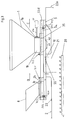
- Fig. 1 is a device for feeding Raw material in a plasticizer 2 with an in a housing 22 with fill opening 21 rotatably driven Screw 20 shown using the example of an extrusion machine.
- the device comprises a hopper 1 for the raw material to be supplied, which in a slide guide 5 trained funnel guide is slidably guided and in 1 with its outlet opening 1b over the filling opening 21 of the plasticizing device 2 is positioned to feed the raw material.
- the sliding guide 5 comprises a by means of screws 10 on the housing 22 of the Plasticizer 2 attached base 51 which in Area of the filling opening 21 one with this has corresponding through bore 55.
- the Base plate 51 are on opposite sides and parallel to each other side guide rails 52 Screws 9 attached, which has an approximately L-shaped cross section exhibit.
- On the base plate 51 and between the two Side guide rails 52 is a slide plate 3 along the Sliding plane S slidably guided and the hopper 1 is with its outlet opening 1b side 1a attached to the sliding plate 3. While the sliding guide 5 with base plate 51 and side guide rails 52 stationary with is connected to the housing of the plasticizer the sliding plate 3 and the hopper 1 attached to it movable, namely in the sliding guide 5 movable parts represents.
- the sliding plate 3 has one with the outlet opening 1b of the Filling funnel 1 corresponding through hole 35, so that when the hopper is positioned accordingly 1, as shown in Fig. 1, the supply of Raw material via the hopper 1, the Exit opening 1b, the passage opening 35 in the Sliding plate and the corresponding one Through opening 55 in the base plate in the below located filling opening 21 of the housing 22 can be effected.
- This position of the hopper 1 represents the Operating position, in which a feed of the raw material from the hopper 1 into the filling opening 21 of the Housing 22 of the plasticizing device 2 is made possible.
- a signal transmitter provided with its two parts 70.1, 70.2, the Signal generator part 70.1 fixed to the sliding guide 5 and the signal transmitter part 70.2 on the filling funnel 1 or whose sliding guide 3 is attached and in the event of a shift of the hopper 1 in the sliding guide 5 according to arrow A is moved accordingly.
- FIG. 1 shown end position in which the hopper above the Filling opening 21 of the housing 22 is positioned, the two signal generator parts 70.1, 70.2 to each other and enter corresponding signal to a not shown Control, which then the drive of the worm 20th enables.
- the hopper 1 according to arrow A in Fig. 1 after shifted to the right within the sliding guide 5, for example in order to make the filling opening 21 accessible for cleaning purposes make, goes from the inside of the plasticizer 2 driven worm 20 from a significant danger, such as has already been explained above. Simultaneously with the Movement of the hopper 1 in the direction of arrow A
- the two signal generator parts 70.1, 70.2 inevitably separated and the signal they emitted Stay off. Now you can control the Plasticizer 2 a sudden shutdown of the Drive of the worm 20 are effected, whereby the Screw 20 via the openly accessible fill opening 21 now no longer any dangers for operating personnel go out and the cleaning of the fill opening 21 safely can be carried out.
- the two signal generator parts are 70.1 and 70.2 together and give a corresponding one Signal to the controller, so that the drive of the worm 20th can be switched on again.
- FIG. 7 is a advantageous development of that shown in FIG. 1 Device shown.
- the filling opening 21 of the plasticizing device 2 is not only in the end position shown in dashed lines in FIG. 7 (see Fig. 1) completely covered, but this filling opening 21 is from the via the hopper 1 protruding sliding plate 3 even with a limited Shift in direction of arrow A covered, but none Feed the raw material more from the hopper 1 can be done.
- the signal from already remains the signal generator parts 70.1, 70.2, which signals that no more raw material can be supplied, but it exists no danger for people because the filling opening 21 still is not accessible.
- FIG. 2 Another advantageous embodiment of the invention is shown in 2 shown.
- the hopper 1 can, for example, the supply of raw material during the actual operation of the plasticizing device 2 and the smaller version here, for example Filling funnel 8 for the supply of cleaning granules Cleaning of the screw 20 may be provided.
- a sliding guide for each hopper 1 or 8 corresponding to its outlet opening 1b, 8b Through opening 35a or 35b.
- a change of Raw material can now be brought about by for example the hopper 1 from its in FIG. 2 position shown above the fill opening 21 by a Shift according to arrow A is moved to the right and on the same sliding plate 3 positioned second Filling funnel 8 over the filling opening 21 of the housing 22 is positioned.
- the slide guide 5 advantageously has a such a length L that the sliding guide 3 from a End position in which the hopper 1 over the Filling opening 21 is positioned in a different end position, in which the filling funnel 8 over the filling opening 21st is positioned, is displaceable.
- This time delay of switching off is used in addition, residual material still in the filling opening 21 to process until the drive of the screw 20 is switched off becomes.
- this enables time delays Switching off the change of the hopper 1, 8 without Interruptions in the drive of the screw 20, since the time delay the absence of signals from the Signalers bridged during the shifting movement until again an end position of the sliding plate 3 and corresponding Positioning of the hopper 1 or 8 is done and the respective signal generator 70.1, 70.2 or 71.1, 71.2 again Give signal.
- FIG. 8b shows a simplified arrangement, in which a part 74.1 of a signal transmitter is stationary in the area the filling opening 21 is arranged on the sliding guide 5 and on each hopper 1, 8 a further signal transmitter part 74.2 is attached, which the correct positioning of the respective hopper 1.8 above the fill opening 21 reveals.
- FIG. 8a there is no simpler configuration Detection based on the signal emitted by the signal generator possible whether funnel 8 or funnel 1 over the filling opening 21 is located.
- both partial plates 3a, 3b in each to move an end position of the slide plate 3, i.e. the Sub-plate 3b with the hopper 8 on the left side Stop 50 L and the partial plate 3a with the filling funnel 1 to the right-hand stop 50 R of the slide guide 5.
- the filling opening 21 is now freely accessible from the outside, so that from inside the plasticizing device 2 located snail 20 hazards for the operator can go out when this in the filling opening 21st reaches in and possibly from the rotating Snail 20 can be detected.
- a further signal generator with signal generator parts 73.1, 73.2 provided in the area of the connecting surface of the two Sub-plates 3a, 3b are arranged.
- the sliding guide 5 In order to reduce the weight of the hopper 1 To be able to take up reliably, the sliding guide 5 moreover also in suitable places, for example the Gearbox 22a of the plasticizing device 2 and be supported.
- FIG. 3 is another one advantageous feature of the device. So points this in the area of the base plate 51 of the sliding guide 5 in one from the area with the fill opening corresponding through opening 55 remote area an emptying opening 40 which can be closed by a slide for the hopper 1, through which the hopper can be emptied if one in the hopper 1 amount of raw material no longer in the Plasticizer 2 is to be supplied. This can for example below the emptying opening 40 Connection piece 41 for the attachment of a suitable Container, such as a sack or the like, may be provided.
- a suitable Container such as a sack or the like
- the operation of the here can not Shut-off valve shown to a corresponding signal of the signal generator with the signal generator parts 71.1, 71.2 to be forcibly coupled, which otherwise to capture the End position of the sliding plate 3 with each other connected sub-plates 3a, 3b is used.
- FIGS. 5 and 6 Another possible embodiment of the device for Feeding raw material is shown in FIGS. 5 and 6.
- the Funnel guide as a turret guide with one on the housing stationary circular support disk 61 and one rotatable turret disc located above formed, which is also circular and the same Has outer circumference as the support disk 61.
- the support disk 61 has one with the filling opening 21 of the Housing 22 corresponding and eccentric Through opening 63, while the rotatable around their Center M turret 62 driven several spaced-apart through openings 64.1, 64.2, 64.3, 64.4, which by rotating the turret in Arrow direction E in one with the filling opening 21 of the housing and the through hole 63 of the support disk 61 corresponding position are movable. On this Through openings 64.1 to 64.4 can fill hopper 1.1, 1.2, 1.4 are attached, which then by rotating the Revolver disk 62 in the direction of arrow E depending on the requirement the filling opening 21 of the housing 22 can be positioned. In the present representation according to FIGS. 5 and 6 beyond the through opening 64.3 Hopper, so that when the turret disk rotates 62 in a position in which this through opening 64.3 over the Filling opening 21 is positioned, this filling opening 21 is accessible from outside for cleaning.
- each hopper 1.1, 1.2, 1.4 be equipped with a signal transmitter that provides the correct Determine the positioning over the filling opening 21 and by can signal the corresponding signal delivery to a controller, so that only when located above the fill opening 21 Filling funnel of the screw drive can be switched on can.
- each through opening 64.1 to 64.4 with a signal generator part 75.2 to 78.2 is equipped.
- the signal generator part 75.2 which the Passage opening 64.1 assigned in the turret disk 62 is located on a radius R1 with respect to the Center M of the turret 62, while the others Signal generator parts 76.2, 77.2, 78.2, the through openings 64.2, 64.3 and 64.4 are assigned to each smaller radii R2, R3, R4 on the turret disk 62 are arranged.
- the signal generator parts 75.2, 76.2, 77.2, 78.2 are on the below the turret disk 62 fixed mounting disc 61 corresponding to four Signal generator parts 75.1, 76.1, 77.1, 78.1 side by side each one of the radii R1, R3, R3 and R4 arranged so that when the turret disk 62 is rotated into a position in which one of its through openings 64.1, 64.2, 64.3, 64.4 with the Through opening 63 in the support plate 61 and below located filling opening 21 of the housing corresponds, the corresponding signal transmitter part 75.2, 76.2, 77.2, 78.2 the turret disk 62 with the corresponding signal transmitter part 75.1, 76.1, 77.1, 78.1 according to its positioning one of the radii R1 to R4 cooperates and the delivery of a corresponding signal to the control unit of the device causes.
- this funnel guide designed as a turret guide 6 can by simply turning the turret disk 62 in Arrow direction E a very quick change of the over the Filling opening 21 located funnel 1.1, 1.2 or 1.4 be carried out, resulting in downtimes, for example largely minimized when changing colors or changing raw materials become.
- the turret 62 can of course depending on the task and size also with more or less through openings for Filling funnel should be provided, as is also possible one of the filling opening 21 and the one with it corresponding passage opening 63 in the support disk 61 distant area one with a slider lockable emptying opening for emptying an over the The discharge opening of the funnel.
Landscapes
- Engineering & Computer Science (AREA)
- Mechanical Engineering (AREA)
- Manufacturing & Machinery (AREA)
- Robotics (AREA)
- Processing And Handling Of Plastics And Other Materials For Molding In General (AREA)
- Basic Packing Technique (AREA)
- Extrusion Moulding Of Plastics Or The Like (AREA)
Abstract
Description
- Fig. 1
- in schematisierter Darstellung die Seitenansicht einer erfindungsgemäßen Vorrichtung zum Zuführen von Rohmaterial
- Fig. 2
- in schematisierter Darstellung eine weitere Ausführungsform der Erfindung
- Fig. 3
- in schematisierter Darstellung eine weitere Ausführungsform der Erfindung
- Fig. 4
- einen Schnitt durch die erfindungsgemäße Vorrichtung gemäß Pfeil B in Fig. 2
- Fig. 5
- eine Aufsicht auf eine weitere Ausgestaltungsform der Erfindung
- Fig. 6
- die Seitenansicht der Vorrichtung gemäß Fig. 5
- Fig. 7
- eine Prinzipdarstellung der Vorrichtung gemäß Fig.1
- Fig. 8a
- eine Prinzipdarstellung der erfindungsgemäßen Vorrichtung gemäß Fig. 2
- Fig. 8b
- eine Variante der erfindungsgemäßen Vorrichtung gemäß Fig. 2.
Claims (17)
- Vorrichtung zum Zuführen von Rohmaterial in eine Plastifiziereinrichtung mit einer in einem Gehäuse mit Einfüllöffnung drehbar antreibbaren Schnecke von Spritzgieß- oder Extrusionsmaschinen, umfassend eine auf dem Gehäuse befestigte und der Einfüllöffnung zugeordnete Trichterführung für mindestens einen Einfülltrichter mit Austrittsöffnung für das Rohmaterial, wobei der mindestens eine Einfülltrichter in eine mit der Einfüllöffnung des Gehäuses korrespondierende Position und eine hiervon entfernte Position bewegbar ist, dadurch gekennzeichnet, daß mindestens ein Signalgeber zur Bestimmung der Position des Einfülltrichters (1) in bezug auf die Einfüllöffnung (21) des Gehäuses (22) vorgesehen ist und der Antrieb der Schnecke (20) der Plastifiziereinrichtung (2) mittels eines von dem Signalgeber in Abhängigkeit von der Position des Einfülltrichters (1) abgegebenen Signals an- bzw. abschaltbar ist.
- Vorrichtung nach Anspruch 1,
dadurch gekennzeichnet, daß die Trichterführung als Gleitführung (5) mit einer zu der Einfüllöffnung (21) des Gehäuses (22) korrespondierenden Durchgangsöffnung (55) ausgebildet ist und der Einfülltrichter (1) in der Gleitführung (5) verschiebbar geführt und die Position des Einfülltrichters (1) über der Durchgangsöffnung (55) der Gleitführung (5) mittels des Signalgebers erkennbar und erfaßbar ist. - Vorrichtung nach Anspruch 2,
dadurch gekennzeichnet, daß die Gleitführung (5) von einer am Gehäuse (22) befestigten Grundplatte (51) und an der Grundplatte (51) an einander gegenüberliegenden Seiten und parallel zueinander befestigten Seitenführungsschienen (52) gebildet ist und der Einfülltrichter (1) an seiner die Austrittsöffnung (1b) aufweisenden Seite mit einer Schiebeplatte (3) verbunden ist, die eine mit der Austrittsöffnung (1b) korrespondierende Durchgangsöffnung (35) aufweist, und wobei die Schiebeplatte (3) auf der Grundplatte (51) aufliegt und in der Gleitführung (5) verschiebbar geführt ist. - Vorrichtung nach einem der Ansprüche 1 bis 3,
dadurch gekennzeichnet, daß der Einfülltrichter (1) in der Gleitführung (5) dergestalt zwischen zwei Endpositionen verschiebbar ist, daß er sich in der einen Endposition über der Einfüllöffnung (21) des Gehäuses (22) befindet und in der anderen Endposition die Einfüllöffnung (21) vollständig freigibt und der Signalgeber der Endposition des Einfülltrichters (1) über der Einfüllöffnung (21) zugeordnet ist. - Vorrichtung nach Anspruch 4,
dadurch gekennzeichnet, daß ein weiterer Signalgeber zur Bestimmung der Position des Einfülltrichters (1) in einer die Einfüllöffnung (21) freigebenden Position vorgesehen ist. - Vorrichtung nach einem der Ansprüche 1 bis 3,
dadurch gekennzeichnet, daß zwei Einfülltrichter (1,8) vorgesehen und auf der Schiebeplatte (3) befestigt und in der Gleitführung (5) verschiebbar geführt sind, wobei die Schiebeplatte (3) je eine mit der jeweiligen Austrittsöffnung (1b bzw. 8b) der Einfülltrichter (1 bzw. 8) korrespondierende Durchgangsöffnung aufweist und jeder Einfülltrichter (1,8) mit einem Signalgeber zur Bestimmung seiner Position in bezug auf die Einfüllöffnung (21) des Gehäuses (22) ausgerüstet ist. - Vorrichtung nach einem der Ansprüche 1 bis 3,
dadurch gekennzeichnet, daß zwei Einfülltrichter (1,8) vorgesehen und auf der Schiebeplatte (3) befestigt und in der Gleitführung (5) verschiebbar geführt sind, wobei die Schiebeplatte (3) je eine mit der jeweiligen Austrittsöffnung (1b bzw. 8b) der Einfülltrichter (1 bzw. 8) korrespondierende Durchgangsöffnung aufweist und die Gleitführung (5) eine solche Länge (L) aufweist, daß die Schiebeplatte (3) aus einer Endposition, in der der erste Einfülltrichter (1) über der Einfüllöffnung (21) des Gehäuses (22) positionierbar ist, in eine zweite Endposition, in der der zweite Einfülltrichter (8) über der Einfüllöffnung (21) positionierbar ist, verschiebbar ist und jeder Endposition der Schiebeplatte (3) je ein Signalgeber zur Bestimmung der jeweiligen Endposition zugeordnet ist. - Vorrichtung nach einem der Ansprüche 6 oder 7,
dadurch gekennzeichnet, daß die Schiebeplatte (3) aus zwei lösbar miteinander verbindbaren Teilplatten (3a,3b) gebildet ist und jeder Einfülltrichter (1 bzw. 8) auf einer Teilplatte (3a bzw. 3b) der Schiebeplatte (3) befestigt ist und die Teilplatten (3a,3b) der Schiebeplatte (3) an ihren einander zugewandten Seiten mit einem Signalgeber ausgerüstet sind, dergestalt, daß eine aneinander anliegende Position der Teilplatten (3a,3b) mittels des Signalgebers erkennbar und erfaßbar ist. - Vorrichtung nach Anspruch 1,
dadurch gekennzeichnet, daß die Trichterführung als Revolverführung (6) mit einer auf dem Gehäuse ortsfest angeordneten Tragscheibe (61), die mit einer mit der Einfüllöffnung (21) des Gehäuses (22) korrespondierenden und außermittig in der Tragscheibe (61) ausgebildeten Durchgangsöffnung (63) ausgebildet ist, und einer auf der Tragscheibe (61) angeordneten und um ihren Mittelpunkt (M) drehbar antreibbaren Revolverscheibe (62) ausgebildet ist und die Revolverscheibe (62) mehrere voneinander beabstandete Durchgangsöffnungen (64.1, 64.2, 64.3, 64.4) aufweist, die durch Drehung der Revolverscheibe (62) in eine mit der Einfüllöffnung (21) des Gehäuses (22) und der Durchgangsöffnung (63) der Tragscheibe (61) korrespondierende Position bewegbar sind und über den Durchgangsöffnungen (64.1, 64.2, 64.3, 64.4) der Revolverscheibe (62) Einfülltrichter (1.1, 1.2, 1.4) befestigbar sind und jedem Einfülltrichter und/oder jeder Durchgangsöffnung (64.1, 64.2, 64.3, 64.4) ein Signalgeber zur Bestimmung seiner Position in bezug auf die Einfüllöffnung (21) des Gehäuses (22) zugeordnet ist. - Vorrichtung nach Anspruch 9,
dadurch gekennzeichnet, daß die Signalgeber so angeordnet sind, daß jeder jeweils einem Einfülltrichter und/oder jeder Durchgangsöffnung (64.1, 64.2, 64.3, 64.4) zugeordnete Signalgeber in einem unterschiedlichen radialen Abstand (R1, R2, R3, R4) vom Mittelpunkt (M) der Revolverscheibe (62) angeordnet ist, so daß bei Signalabgabe der jeweilige Einfülltrichter erkennbar ist. - Vorrichtung nach einem der Ansprüche 1 bis 10,
gekennzeichnet durch eine Steuereinheit, mittels derer die von den Signalgebern in Abhängigkeit von der Position der Einfülltrichter und/oder Teilplatten (3a,3b) der Schiebeplatte (3) abgegebenen Signale logisch auswertbar sind, dergestalt, daß eine von der Position der Einfülltrichter in bezug auf die Einfüllöffnung (21) des Gehäuses (22) abhängige An- bzw. Abschaltung des Antriebes der Schnecke bewirkbar ist. - Vorrichtung nach Anspruch 11,
dadurch gekennzeichnet, daß mittels der Steuereinheit eine Erkennung des jeweils über der Einfüllöffnung (21) befindlichen Einfülltrichters bewirkbar ist. - Vorrichtung nach einem der Ansprüche 1 bis 12,
dadurch gekennzeichnet, daß die Trichterführung mit einem elektrischen, pneumatischen oder hydraulischen Antrieb zur Bewegung der Einfülltrichter ausgerüstet ist. - Vorrichtung nach einem der Ansprüche 1 bis 12,
dadurch gekennzeichnet, daß der Signalgeber als Endschalter, wie elektrischer Näherungsschalter, Lichtschranke, mechanischer Grenztaster, Magnetschalter, ausgebildet ist. - Vorrichtung nach einem der Ansprüche 1 bis 14,
dadurch gekennzeichnet, daß die Abschaltung des Antriebes der Schnecke (20) schlagartig durchführbar ist. - Vorrichtung nach einem der Ansprüche 1 bis 14,
dadurch gekennzeichnet, daß die Abschaltung des Antriebes der Schnecke (20) zeitverzögert durchführbar ist. - Vorrichtung nach einem der Ansprüche 1 bis 16,
dadurch gekennzeichnet, daß die Grundplatte oder Tragscheibe der Trichterführung in einem von dem Bereich der mit der Einfüllöffnung korrespondierenden Durchgangsöffnung entfernten Bereich eine mit einem Schieber verschließbare Entleerungsöffnung für einen Einfülltrichter aufweist und der Einfülltrichter in eine mit der Entleerungsöffnung korrespondierende Position bewegbar ist.
Priority Applications (3)
| Application Number | Priority Date | Filing Date | Title |
|---|---|---|---|
| AT97110965T ATE205770T1 (de) | 1997-07-02 | 1997-07-02 | Vorrichtung zum zuführen von rohmaterial in eine plastifiziereinrichtung |
| DE59704663T DE59704663D1 (de) | 1997-07-02 | 1997-07-02 | Vorrichtung zum Zuführen von Rohmaterial in eine Plastifiziereinrichtung |
| EP97110965A EP0888857B1 (de) | 1997-07-02 | 1997-07-02 | Vorrichtung zum Zuführen von Rohmaterial in eine Plastifiziereinrichtung |
Applications Claiming Priority (1)
| Application Number | Priority Date | Filing Date | Title |
|---|---|---|---|
| EP97110965A EP0888857B1 (de) | 1997-07-02 | 1997-07-02 | Vorrichtung zum Zuführen von Rohmaterial in eine Plastifiziereinrichtung |
Publications (2)
| Publication Number | Publication Date |
|---|---|
| EP0888857A1 true EP0888857A1 (de) | 1999-01-07 |
| EP0888857B1 EP0888857B1 (de) | 2001-09-19 |
Family
ID=8227003
Family Applications (1)
| Application Number | Title | Priority Date | Filing Date |
|---|---|---|---|
| EP97110965A Expired - Lifetime EP0888857B1 (de) | 1997-07-02 | 1997-07-02 | Vorrichtung zum Zuführen von Rohmaterial in eine Plastifiziereinrichtung |
Country Status (3)
| Country | Link |
|---|---|
| EP (1) | EP0888857B1 (de) |
| AT (1) | ATE205770T1 (de) |
| DE (1) | DE59704663D1 (de) |
Cited By (5)
| Publication number | Priority date | Publication date | Assignee | Title |
|---|---|---|---|---|
| CN110404699A (zh) * | 2019-08-20 | 2019-11-05 | 惠州市创鑫隆实业有限公司 | 自动化塑料喷涂机 |
| WO2021170443A1 (de) * | 2020-02-27 | 2021-09-02 | Hebenstreit Gmbh | Verfahren zur zuführung einer rohstoffmenge in eine produktionsmaschine, sowie vorrichtung und verfahren zur herstellung eines lebensmittelprodukts |
| WO2021170445A1 (de) * | 2020-02-27 | 2021-09-02 | Hebenstreit Gmbh | Verfahren und vorrichtung zur herstellung eines lebensmittelprodukts |
| CN113733470A (zh) * | 2020-05-28 | 2021-12-03 | 精工爱普生株式会社 | 材料供给装置、射出成型装置及三维造型装置 |
| CN118809921A (zh) * | 2024-08-16 | 2024-10-22 | 江西融贤声学科技有限公司 | 一种汽车零部件批量注塑装置 |
Citations (6)
| Publication number | Priority date | Publication date | Assignee | Title |
|---|---|---|---|---|
| GB1360494A (en) * | 1971-06-25 | 1974-07-17 | Grollet J | Apparatus for selectively supplying materials having different characteristics to an outlet |
| FR2531000A1 (fr) * | 1982-07-28 | 1984-02-03 | Hehl Karl | Dispositif permettant d'alimenter en granules une unite de moulage par injection |
| JPS5922711A (ja) * | 1982-07-30 | 1984-02-06 | Sumitomo Heavy Ind Ltd | 粉・粒状材料の供給・交換装置 |
| DE3529523C1 (de) * | 1985-08-17 | 1986-11-20 | Schleberger, Albert, 5600 Wuppertal | Mess- und Regeleinrichtung fuer einen Schneckenextruder zum Verarbeiten thermoplastischer Massen und Schneckenextruder mit einer derartigen Mess- und Regeleinrichtung |
| EP0335298A2 (de) * | 1988-03-30 | 1989-10-04 | Karl Hehl | Kunststoffwechseleinrichtung an einer Kunststoff-Spritzgiesseinheit |
| EP0349799A2 (de) * | 1988-07-07 | 1990-01-10 | Karl Hehl | Kunststoff-Spritzgiesseinheit |
-
1997
- 1997-07-02 DE DE59704663T patent/DE59704663D1/de not_active Expired - Fee Related
- 1997-07-02 AT AT97110965T patent/ATE205770T1/de not_active IP Right Cessation
- 1997-07-02 EP EP97110965A patent/EP0888857B1/de not_active Expired - Lifetime
Patent Citations (6)
| Publication number | Priority date | Publication date | Assignee | Title |
|---|---|---|---|---|
| GB1360494A (en) * | 1971-06-25 | 1974-07-17 | Grollet J | Apparatus for selectively supplying materials having different characteristics to an outlet |
| FR2531000A1 (fr) * | 1982-07-28 | 1984-02-03 | Hehl Karl | Dispositif permettant d'alimenter en granules une unite de moulage par injection |
| JPS5922711A (ja) * | 1982-07-30 | 1984-02-06 | Sumitomo Heavy Ind Ltd | 粉・粒状材料の供給・交換装置 |
| DE3529523C1 (de) * | 1985-08-17 | 1986-11-20 | Schleberger, Albert, 5600 Wuppertal | Mess- und Regeleinrichtung fuer einen Schneckenextruder zum Verarbeiten thermoplastischer Massen und Schneckenextruder mit einer derartigen Mess- und Regeleinrichtung |
| EP0335298A2 (de) * | 1988-03-30 | 1989-10-04 | Karl Hehl | Kunststoffwechseleinrichtung an einer Kunststoff-Spritzgiesseinheit |
| EP0349799A2 (de) * | 1988-07-07 | 1990-01-10 | Karl Hehl | Kunststoff-Spritzgiesseinheit |
Non-Patent Citations (1)
| Title |
|---|
| PATENT ABSTRACTS OF JAPAN vol. 008, no. 112 (M - 298) 25 May 1984 (1984-05-25) * |
Cited By (5)
| Publication number | Priority date | Publication date | Assignee | Title |
|---|---|---|---|---|
| CN110404699A (zh) * | 2019-08-20 | 2019-11-05 | 惠州市创鑫隆实业有限公司 | 自动化塑料喷涂机 |
| WO2021170443A1 (de) * | 2020-02-27 | 2021-09-02 | Hebenstreit Gmbh | Verfahren zur zuführung einer rohstoffmenge in eine produktionsmaschine, sowie vorrichtung und verfahren zur herstellung eines lebensmittelprodukts |
| WO2021170445A1 (de) * | 2020-02-27 | 2021-09-02 | Hebenstreit Gmbh | Verfahren und vorrichtung zur herstellung eines lebensmittelprodukts |
| CN113733470A (zh) * | 2020-05-28 | 2021-12-03 | 精工爱普生株式会社 | 材料供给装置、射出成型装置及三维造型装置 |
| CN118809921A (zh) * | 2024-08-16 | 2024-10-22 | 江西融贤声学科技有限公司 | 一种汽车零部件批量注塑装置 |
Also Published As
| Publication number | Publication date |
|---|---|
| ATE205770T1 (de) | 2001-10-15 |
| EP0888857B1 (de) | 2001-09-19 |
| DE59704663D1 (de) | 2001-10-25 |
Similar Documents
| Publication | Publication Date | Title |
|---|---|---|
| DE3228161C1 (de) | Beschickungseinrichtung zum Zufuehren von Kunststoffgranulat in eine Spritzgiesseinheit | |
| EP1882580B1 (de) | Wechselbehälter | |
| DE2657908B2 (de) | Peristaltische Pumpe | |
| DE2047398A1 (de) | Vorrichtung zur Verarbeitung preß barer Massen | |
| EP0193647A1 (de) | Verfahren und Steuerung für eine Maschine zum Abtragen von Faserflocken von Textilfaserballen | |
| EP0585664B1 (de) | Kunststoff-Spritzgiessmaschine | |
| DE3007002A1 (de) | Verbesserungen an beschickungsvorrichtungen der zigaretten-behaelter fuer zigaretten-abpackmaschinen | |
| EP1259326B1 (de) | Aufsatz für aktenvernichter zur aufnahme und zuführung von schriftgut | |
| EP0888857B1 (de) | Vorrichtung zum Zuführen von Rohmaterial in eine Plastifiziereinrichtung | |
| DE2912218A1 (de) | Zufuhreinrichtung fuer zerkleinerungsmaschinen | |
| DE10003625C1 (de) | Sortiervorrichtung für becherförmige Gegenstände | |
| DE2401128A1 (de) | Stangenzufuehrungsvorrichtung | |
| DE69114879T2 (de) | Vorrichtung zum Dosieren in Formen. | |
| DE3241435C2 (de) | Verfahren sowie Anordnung zur gemeinsamen Höhenverstellung eines Behandlungs-, Kontroll- oder dergleichen Organe aufweisenden Trägers und einer diesen zugeordneten Maschineneinrichtung einer Gefäßbehandlungs-, Kontroll- oder dergleichen Maschine | |
| DE3628146C2 (de) | ||
| EP0628512B1 (de) | Füllorgan mit in der Höhe verstellbarem Rückgasrohr | |
| EP3170775A1 (de) | Zwischenspeicher für stückgut | |
| DE3810732C1 (de) | ||
| DE3209687C2 (de) | Fahrbare Knet- und Mischmaschine | |
| DE8810248U1 (de) | Vorrichtung zum Bewegen des Greifers eines Einlegers | |
| DE974666C (de) | Elektrische Vorrichtung zum selbsttaetigen Steuern des Vorschubs eines Maschinenteiles, beispielsweise des Tisches einer Werkzeugmaschine | |
| EP0921500B1 (de) | Vorrichtung und Anordnung zum Speichern von Münzen mit deren Zwischenspeicherung | |
| DE1167689B (de) | Geraet zur Erzeugung feinbearbeiteter Flaechen an Werkstuecken | |
| DE69826169T2 (de) | Antriebsmechanismus fuer einen Ausnehmerarm | |
| DE3034979C2 (de) |
Legal Events
| Date | Code | Title | Description |
|---|---|---|---|
| PUAI | Public reference made under article 153(3) epc to a published international application that has entered the european phase |
Free format text: ORIGINAL CODE: 0009012 |
|
| AK | Designated contracting states |
Kind code of ref document: A1 Designated state(s): AT CH DE DK GB IT LI SE |
|
| RAP1 | Party data changed (applicant data changed or rights of an application transferred) |
Owner name: MANN + HUMMEL PROTEC GMBH |
|
| 17P | Request for examination filed |
Effective date: 19990313 |
|
| AKX | Designation fees paid |
Free format text: AT CH DE DK GB IT LI SE |
|
| 17Q | First examination report despatched |
Effective date: 20000420 |
|
| GRAG | Despatch of communication of intention to grant |
Free format text: ORIGINAL CODE: EPIDOS AGRA |
|
| RIN1 | Information on inventor provided before grant (corrected) |
Inventor name: VOLLMAR, HARTMUT |
|
| GRAG | Despatch of communication of intention to grant |
Free format text: ORIGINAL CODE: EPIDOS AGRA |
|
| GRAH | Despatch of communication of intention to grant a patent |
Free format text: ORIGINAL CODE: EPIDOS IGRA |
|
| GRAH | Despatch of communication of intention to grant a patent |
Free format text: ORIGINAL CODE: EPIDOS IGRA |
|
| GRAA | (expected) grant |
Free format text: ORIGINAL CODE: 0009210 |
|
| AK | Designated contracting states |
Kind code of ref document: B1 Designated state(s): AT CH DE DK GB IT LI SE |
|
| REF | Corresponds to: |
Ref document number: 205770 Country of ref document: AT Date of ref document: 20011015 Kind code of ref document: T |
|
| REG | Reference to a national code |
Ref country code: CH Ref legal event code: EP |
|
| REF | Corresponds to: |
Ref document number: 59704663 Country of ref document: DE Date of ref document: 20011025 |
|
| PG25 | Lapsed in a contracting state [announced via postgrant information from national office to epo] |
Ref country code: SE Free format text: LAPSE BECAUSE OF FAILURE TO SUBMIT A TRANSLATION OF THE DESCRIPTION OR TO PAY THE FEE WITHIN THE PRESCRIBED TIME-LIMIT Effective date: 20011219 Ref country code: DK Free format text: LAPSE BECAUSE OF FAILURE TO SUBMIT A TRANSLATION OF THE DESCRIPTION OR TO PAY THE FEE WITHIN THE PRESCRIBED TIME-LIMIT Effective date: 20011219 |
|
| REG | Reference to a national code |
Ref country code: GB Ref legal event code: IF02 |
|
| GBT | Gb: translation of ep patent filed (gb section 77(6)(a)/1977) |
Effective date: 20011201 |
|
| PG25 | Lapsed in a contracting state [announced via postgrant information from national office to epo] |
Ref country code: AT Free format text: LAPSE BECAUSE OF NON-PAYMENT OF DUE FEES Effective date: 20020702 |
|
| PLBE | No opposition filed within time limit |
Free format text: ORIGINAL CODE: 0009261 |
|
| STAA | Information on the status of an ep patent application or granted ep patent |
Free format text: STATUS: NO OPPOSITION FILED WITHIN TIME LIMIT |
|
| PG25 | Lapsed in a contracting state [announced via postgrant information from national office to epo] |
Ref country code: LI Free format text: LAPSE BECAUSE OF NON-PAYMENT OF DUE FEES Effective date: 20020731 Ref country code: CH Free format text: LAPSE BECAUSE OF NON-PAYMENT OF DUE FEES Effective date: 20020731 |
|
| 26N | No opposition filed | ||
| REG | Reference to a national code |
Ref country code: CH Ref legal event code: PL |
|
| PGFP | Annual fee paid to national office [announced via postgrant information from national office to epo] |
Ref country code: GB Payment date: 20060720 Year of fee payment: 10 |
|
| PGFP | Annual fee paid to national office [announced via postgrant information from national office to epo] |
Ref country code: IT Payment date: 20060731 Year of fee payment: 10 |
|
| PGFP | Annual fee paid to national office [announced via postgrant information from national office to epo] |
Ref country code: DE Payment date: 20070719 Year of fee payment: 11 |
|
| GBPC | Gb: european patent ceased through non-payment of renewal fee |
Effective date: 20070702 |
|
| PG25 | Lapsed in a contracting state [announced via postgrant information from national office to epo] |
Ref country code: GB Free format text: LAPSE BECAUSE OF NON-PAYMENT OF DUE FEES Effective date: 20070702 |
|
| PG25 | Lapsed in a contracting state [announced via postgrant information from national office to epo] |
Ref country code: DE Free format text: LAPSE BECAUSE OF NON-PAYMENT OF DUE FEES Effective date: 20090203 |
|
| PG25 | Lapsed in a contracting state [announced via postgrant information from national office to epo] |
Ref country code: IT Free format text: LAPSE BECAUSE OF NON-PAYMENT OF DUE FEES Effective date: 20070702 |