EP0889288A1 - Brenner, insbesondere Gasbrenner - Google Patents
Brenner, insbesondere Gasbrenner Download PDFInfo
- Publication number
- EP0889288A1 EP0889288A1 EP98111308A EP98111308A EP0889288A1 EP 0889288 A1 EP0889288 A1 EP 0889288A1 EP 98111308 A EP98111308 A EP 98111308A EP 98111308 A EP98111308 A EP 98111308A EP 0889288 A1 EP0889288 A1 EP 0889288A1
- Authority
- EP
- European Patent Office
- Prior art keywords
- combustion chamber
- porous body
- condensate
- burner
- walls
- Prior art date
- Legal status (The legal status is an assumption and is not a legal conclusion. Google has not performed a legal analysis and makes no representation as to the accuracy of the status listed.)
- Granted
Links
- 238000002485 combustion reaction Methods 0.000 claims abstract description 44
- 239000000919 ceramic Substances 0.000 claims abstract description 4
- 239000006260 foam Substances 0.000 claims abstract description 4
- 239000006262 metallic foam Substances 0.000 claims abstract description 3
- 238000001704 evaporation Methods 0.000 claims description 3
- 230000008020 evaporation Effects 0.000 claims description 3
- 238000001816 cooling Methods 0.000 description 3
- 239000000203 mixture Substances 0.000 description 3
- 230000007797 corrosion Effects 0.000 description 2
- 238000005260 corrosion Methods 0.000 description 2
- 239000000446 fuel Substances 0.000 description 2
- 241001156002 Anthonomus pomorum Species 0.000 description 1
- 241000446313 Lamella Species 0.000 description 1
- 238000009833 condensation Methods 0.000 description 1
- 230000005494 condensation Effects 0.000 description 1
- 239000004744 fabric Substances 0.000 description 1
- 231100001261 hazardous Toxicity 0.000 description 1
- 238000009413 insulation Methods 0.000 description 1
- 239000011148 porous material Substances 0.000 description 1
- 239000002244 precipitate Substances 0.000 description 1
- 239000007787 solid Substances 0.000 description 1
- 239000006228 supernatant Substances 0.000 description 1
Images
Classifications
-
- F—MECHANICAL ENGINEERING; LIGHTING; HEATING; WEAPONS; BLASTING
- F24—HEATING; RANGES; VENTILATING
- F24H—FLUID HEATERS, e.g. WATER OR AIR HEATERS, HAVING HEAT-GENERATING MEANS, e.g. HEAT PUMPS, IN GENERAL
- F24H8/00—Fluid heaters characterised by means for extracting latent heat from flue gases by means of condensation
- F24H8/006—Means for removing condensate from the heater
-
- F—MECHANICAL ENGINEERING; LIGHTING; HEATING; WEAPONS; BLASTING
- F23—COMBUSTION APPARATUS; COMBUSTION PROCESSES
- F23M—CASINGS, LININGS, WALLS OR DOORS SPECIALLY ADAPTED FOR COMBUSTION CHAMBERS, e.g. FIREBRIDGES; DEVICES FOR DEFLECTING AIR, FLAMES OR COMBUSTION PRODUCTS IN COMBUSTION CHAMBERS; SAFETY ARRANGEMENTS SPECIALLY ADAPTED FOR COMBUSTION APPARATUS; DETAILS OF COMBUSTION CHAMBERS, NOT OTHERWISE PROVIDED FOR
- F23M5/00—Casings; Linings; Walls
- F23M5/08—Cooling thereof; Tube walls
-
- F—MECHANICAL ENGINEERING; LIGHTING; HEATING; WEAPONS; BLASTING
- F23—COMBUSTION APPARATUS; COMBUSTION PROCESSES
- F23M—CASINGS, LININGS, WALLS OR DOORS SPECIALLY ADAPTED FOR COMBUSTION CHAMBERS, e.g. FIREBRIDGES; DEVICES FOR DEFLECTING AIR, FLAMES OR COMBUSTION PRODUCTS IN COMBUSTION CHAMBERS; SAFETY ARRANGEMENTS SPECIALLY ADAPTED FOR COMBUSTION APPARATUS; DETAILS OF COMBUSTION CHAMBERS, NOT OTHERWISE PROVIDED FOR
- F23M2900/00—Special features of, or arrangements for combustion chambers
- F23M2900/05001—Preventing corrosion by using special lining materials or other techniques
-
- Y—GENERAL TAGGING OF NEW TECHNOLOGICAL DEVELOPMENTS; GENERAL TAGGING OF CROSS-SECTIONAL TECHNOLOGIES SPANNING OVER SEVERAL SECTIONS OF THE IPC; TECHNICAL SUBJECTS COVERED BY FORMER USPC CROSS-REFERENCE ART COLLECTIONS [XRACs] AND DIGESTS
- Y02—TECHNOLOGIES OR APPLICATIONS FOR MITIGATION OR ADAPTATION AGAINST CLIMATE CHANGE
- Y02B—CLIMATE CHANGE MITIGATION TECHNOLOGIES RELATED TO BUILDINGS, e.g. HOUSING, HOUSE APPLIANCES OR RELATED END-USER APPLICATIONS
- Y02B30/00—Energy efficient heating, ventilation or air conditioning [HVAC]
Definitions
- the invention relates to a burner with a combustion chamber, the combustion chamber walls has, wherein the combustion chamber is a heat-generating burner is assigned, and being on the combustion chamber walls, the combustion chamber facing condensate traps are arranged.
- Such a burner is known from AT 2163.
- the grids are at a distance from the Combustion chamber walls. The distance is smaller than the diameter of a condensate drop chosen. If condensate drops now form, so can do not drain them from the cool combustion chamber wall. This does not result in any Zones in which the condensate collects and concentrated corrosion damage evokes.
- the condensate evenly distributed over the firewalls can only develop its corrosive effects locally.
- the grids have only a limited storage capacity for the condensate. When this is exhausted, the condensate flows in an uncontrolled manner which leads to the known problems.
- the condensate collecting device is designed as a porous body, the inside of a Channel structure is crossed and the area directly on the combustion chamber wall is put on.
- the porous body forms a compact memory block in which the condensate is absorbed.
- the channel structure has a capillary effect with which the condensate is sucked up. Because the condensate completely from the burner wall, no more corrosion can occur.
- the Combustion chamber walls are cooled and that the porous body (s) in the area of the cooled zones are arranged.
- the porous bodies are therefore positioned at those places where the Condensate will arise.
- the burners are designed so that the porous body starts out extends from the cooled zone to an area of the combustion chamber, in which the temperature above the evaporation temperature of the Condensate is then the absorbed condensate is immediately again transported out of the porous body.
- the condensate into the fuel / air supply zone of the burner.
- the fuel mixture is thus humidified to reduce NOx.
- the porous materials should consist of fiber-free solids, that are not hazardous to health. In this sense, the porous body consist of a fine porous ceramic foam or a metal foam. These fabrics are dimensionally stable and easy to use. Last but not least, they can can also be obtained cheaply.
- porous body as a bed consisting of a A large number of partial bodies is formed in a holder on the combustion chamber wall are accommodated.
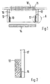
- FIG. 1 shows a burner with a combustion chamber 16.
- the combustion chamber 16 is surrounded by the combustion chamber walls 12. Is over the combustion chamber 16 a heat exchanger arranged.
- the heat exchanger consists of several, in the cooling tubes 10 lying one behind the other in the image plane. These cooling tubes 10 pass through a slat block 11.
- a burner plate 14 is located below the combustion chamber 16.
- the burner plate 14 is connected to an intake duct made in the drawing Not shown for reasons of clarity. Via the intake duct the burner plate 14 fed a gas-air mixture.
- the burner plate 14 facing lower edge area are on the Combustion chamber walls 12 placed on porous bodies 13.
- the porous bodies 13 form a closed ring that surrounds the combustion chamber walls 12 covers.
- the porous bodies 13 are flat on the combustion chamber walls 12 put on. Inside, they are crossed by a channel structure.
- the clear widths of the individual channels are designed so that a capillary action can arise. Use is suitable here, for example a ceramic foam.
- the gas-air mixture supplied is burned on the burner plate 14.
- the heat generated is fed to the heat exchanger, which transfers it his lamella block 11 leads the cooling tubes 10.
- condensation can form. This is especially the case Case when the combustion chamber walls are themselves cooled.
- the condensate runs along the combustion chamber wall 12 towards the porous bodies 13. Here it will be in the contact zone between the combustion chamber wall 12 and the porous bodies 13 added and uniform due to the capillary action distributed in the porous body 13.
- FIG. 2 shows the arrangement of a porous body 13 on a combustion chamber wall 12 on an enlarged scale.
- the porous body 13 is in the region of a cooled zone 15 arranged.
- the porous body 13 takes the condensate, which is on this cooled zone 15 precipitates.
- the porous body 13 projects into the combustion chamber 16.
- the supernatant in the direction of the combustion chamber 16 is chosen so that the porous Body 13 is partially arranged in an area at which a temperature prevails above the evaporation temperature of the condensate. This has to Consequence that the condensate evaporates from the porous body 13.
- the condensate is discharged directly from the container wall 12 and is evaporated again.
Landscapes
- Engineering & Computer Science (AREA)
- Chemical & Material Sciences (AREA)
- Combustion & Propulsion (AREA)
- Mechanical Engineering (AREA)
- General Engineering & Computer Science (AREA)
- Physics & Mathematics (AREA)
- Thermal Sciences (AREA)
- Wick-Type Burners And Burners With Porous Materials (AREA)
- Spray-Type Burners (AREA)
- Gas Burners (AREA)
Abstract
Description
- Fig.1
- Eine schematische Darstellung eines Brenners und
- Fig.2
- ein in der Fig.1 mit A dargestelltes, vergrößert gezeigtes Detail.
Claims (6)
- Brenner mit einer Brennkammer, die Brennkammerwände aufweist, wobei der Brennkammer ein wärmeentwickelnder Brennkörper zugeordnet ist, und wobei an den Brennkammerwänden der Brennkammer zugekehrt Kondensat-Auffangvorrichtungen angeordnet sind,
dadurch gekennzeichnet,daß die Kondensat-Auffangvorrichtung als poröser Körper (13) ausgebildet ist, der im Inneren von einer Kanalstruktur durchzogen ist und der flächig direkt auf die Brennkammerwand (13) aufgesetzt ist. - Brenner nach Anspruch 1,
dadurch gekennzeichnet,daß die Brennkammerwände (12) gekühlt sind, unddaß der/die porösen Körper (13) im Bereich der gekühlten Zonen angeordnet sind. - Brenner nach Anspruch 2,
dadurch gekennzeichnet,daß der poröse Körper (13) sich ausgehend von der gekühlten Zone bis hin in einen Bereich der Brennkammer (16) erstreckt in der die Temperatur oberhalb der Verdampfungsteperatur des Kondensats liegt. - Brenner nach Anspruch 1 oder 2,
dadurch gekennzeichnet,daß die Brennkammerwäande (12) vollständig mit wärmeisolierenden, porösen Körpern (13) verkleidet sind. - Brenner nach einem der Ansprüche 1 bis 4,
dadurch gekennzeichnet,daß der poröse Körper (13) als feinporöser Keramikschaum oder als Metallschaum ausgebildet ist. - Brenner nach einem der Ansprüche 1 bis 4,
dadurch gekennzeichnet,daß der poröse Körper (13) als Schüttung bestehend aus einer Vielzahl von Teilkörpern ausgebildet ist, die in einer Halterung an der Brennkammerwand (12) untergebracht sind.
Applications Claiming Priority (2)
| Application Number | Priority Date | Filing Date | Title |
|---|---|---|---|
| DE19728397 | 1997-07-03 | ||
| DE19728397A DE19728397C1 (de) | 1997-07-03 | 1997-07-03 | Brenner, insbesondere Gasbrenner |
Publications (2)
| Publication Number | Publication Date |
|---|---|
| EP0889288A1 true EP0889288A1 (de) | 1999-01-07 |
| EP0889288B1 EP0889288B1 (de) | 2002-05-02 |
Family
ID=7834512
Family Applications (1)
| Application Number | Title | Priority Date | Filing Date |
|---|---|---|---|
| EP98111308A Expired - Lifetime EP0889288B1 (de) | 1997-07-03 | 1998-06-19 | Brenner, insbesondere Gasbrenner |
Country Status (3)
| Country | Link |
|---|---|
| EP (1) | EP0889288B1 (de) |
| AT (1) | ATE217067T1 (de) |
| DE (2) | DE19728397C1 (de) |
Cited By (1)
| Publication number | Priority date | Publication date | Assignee | Title |
|---|---|---|---|---|
| EP3524882A1 (de) * | 2018-02-09 | 2019-08-14 | Vaillant GmbH | Wärmezelle mit metallischem dämmring |
Families Citing this family (1)
| Publication number | Priority date | Publication date | Assignee | Title |
|---|---|---|---|---|
| DE102009049574A1 (de) * | 2009-10-15 | 2011-04-28 | Lichtblick Zuhausekraftwerk Gmbh | Vorrichtung zum Abführen von Kondensat |
Citations (4)
| Publication number | Priority date | Publication date | Assignee | Title |
|---|---|---|---|---|
| DE3331340A1 (de) * | 1983-08-31 | 1985-04-11 | Buderus Ag, 6330 Wetzlar | Zentralheizungskessel |
| CH679801A5 (de) * | 1989-02-02 | 1992-04-15 | Vaillant Gmbh | |
| AT399034B (de) * | 1991-06-03 | 1995-03-27 | Vaillant Gmbh | Doppelwandiger heizschacht |
| AT399934B (de) * | 1991-06-03 | 1995-08-25 | Vaillant Gmbh | Brennkammermantel |
Family Cites Families (3)
| Publication number | Priority date | Publication date | Assignee | Title |
|---|---|---|---|---|
| DE3442467C2 (de) * | 1984-11-22 | 1995-11-16 | Koerting Ag | Niedertemperatur-Heizkessel |
| DE19534284A1 (de) * | 1995-09-15 | 1997-03-20 | Viessmann Werke Kg | Heizkessel für flüssige oder gasförmige Brennstoffe |
| DE19541803B4 (de) * | 1995-11-09 | 2013-06-27 | Robert Bosch Gmbh | Wärmeübertrager für gasbeheizte Wassererhitzer |
-
1997
- 1997-07-03 DE DE19728397A patent/DE19728397C1/de not_active Expired - Fee Related
-
1998
- 1998-06-19 AT AT98111308T patent/ATE217067T1/de not_active IP Right Cessation
- 1998-06-19 EP EP98111308A patent/EP0889288B1/de not_active Expired - Lifetime
- 1998-06-19 DE DE59803967T patent/DE59803967D1/de not_active Expired - Fee Related
Patent Citations (4)
| Publication number | Priority date | Publication date | Assignee | Title |
|---|---|---|---|---|
| DE3331340A1 (de) * | 1983-08-31 | 1985-04-11 | Buderus Ag, 6330 Wetzlar | Zentralheizungskessel |
| CH679801A5 (de) * | 1989-02-02 | 1992-04-15 | Vaillant Gmbh | |
| AT399034B (de) * | 1991-06-03 | 1995-03-27 | Vaillant Gmbh | Doppelwandiger heizschacht |
| AT399934B (de) * | 1991-06-03 | 1995-08-25 | Vaillant Gmbh | Brennkammermantel |
Cited By (1)
| Publication number | Priority date | Publication date | Assignee | Title |
|---|---|---|---|---|
| EP3524882A1 (de) * | 2018-02-09 | 2019-08-14 | Vaillant GmbH | Wärmezelle mit metallischem dämmring |
Also Published As
| Publication number | Publication date |
|---|---|
| DE19728397C1 (de) | 1999-01-14 |
| EP0889288B1 (de) | 2002-05-02 |
| ATE217067T1 (de) | 2002-05-15 |
| DE59803967D1 (de) | 2002-06-06 |
Similar Documents
| Publication | Publication Date | Title |
|---|---|---|
| DE60308696T2 (de) | Wärmetauscher für ein brennwertgerät mit doppelrohrbündel | |
| DE1053469B (de) | Fraktionierkolonne | |
| DE102008035394B3 (de) | Schwadenapparat, insbesondere für Stikkenofen | |
| EP1710524B1 (de) | Luftkondensator | |
| EP0499883A1 (de) | Wärmetauscher | |
| EP0889288B1 (de) | Brenner, insbesondere Gasbrenner | |
| EP0164098A2 (de) | Wärmetauscher | |
| CH636942A5 (de) | Wirbelschichtfeuerung mit einem ebenen rost. | |
| DE761677C (de) | Kuehlvorrichtung fuer Gasturbinen | |
| DE2518067A1 (de) | Waermetauscher und dessen verwendung zum kuehlen heisser gase | |
| DE2009377C3 (de) | Kältemitteldampf -Generator | |
| DE19718885C2 (de) | Gasbrenner | |
| EP0338343A2 (de) | Kühleinschubeinheit für Schalt- und Steuerschränke | |
| DE2724880A1 (de) | Kastenfoermiger, an einen schaltschrank vorzugsweise ansetzbarer kuehler | |
| DE2628925C2 (de) | Gerät zum Heizen von Luft | |
| DE3406028C2 (de) | Gerät zum Erwärmen von Wasser, insb. Warmwasserheizkessel | |
| DE1501488B2 (de) | Speicher-Umschaltwärmetauscher | |
| DE708019C (de) | Halbgasfeuerung mit einem auf der Brennstoffaufgabeseite angeordneten Steilrost und wassergesaettigter Unterwindzufuehrung | |
| DE1454369C (de) | Heizkessel | |
| DE19819138C2 (de) | Feuerungsanlage | |
| DE4032264A1 (de) | Vorrichtung zur rueckgewinnung von waerme aus den abgasen aus feuerungsanlagen und produktionsprozessen | |
| DE1758267C (de) | Kuhlkamin | |
| DE10152705B4 (de) | Trocknungsanlage für schüttfähige Güter, insbesondere landwirtschaftliche Produkte | |
| DE2048404C3 (de) | Vorrichtung zum Vorwärmen von körnigem und granuliertem Material | |
| DE3028214C2 (de) | Beheizung für den Kocher einer, insbesondere direkt befeuerten, Absorptionswärmepumpe |
Legal Events
| Date | Code | Title | Description |
|---|---|---|---|
| PUAI | Public reference made under article 153(3) epc to a published international application that has entered the european phase |
Free format text: ORIGINAL CODE: 0009012 |
|
| AK | Designated contracting states |
Kind code of ref document: A1 Designated state(s): AT DE FR GB IT |
|
| AX | Request for extension of the european patent |
Free format text: AL;LT;LV;MK;RO;SI |
|
| K1C3 | Correction of patent application (complete document) published |
Effective date: 19990107 |
|
| 17P | Request for examination filed |
Effective date: 19990707 |
|
| AKX | Designation fees paid |
Free format text: AT DE FR GB IT |
|
| GRAG | Despatch of communication of intention to grant |
Free format text: ORIGINAL CODE: EPIDOS AGRA |
|
| 17Q | First examination report despatched |
Effective date: 20010710 |
|
| GRAG | Despatch of communication of intention to grant |
Free format text: ORIGINAL CODE: EPIDOS AGRA |
|
| GRAH | Despatch of communication of intention to grant a patent |
Free format text: ORIGINAL CODE: EPIDOS IGRA |
|
| REG | Reference to a national code |
Ref country code: GB Ref legal event code: IF02 |
|
| GRAH | Despatch of communication of intention to grant a patent |
Free format text: ORIGINAL CODE: EPIDOS IGRA |
|
| GRAA | (expected) grant |
Free format text: ORIGINAL CODE: 0009210 |
|
| AK | Designated contracting states |
Kind code of ref document: B1 Designated state(s): AT DE FR GB IT |
|
| REF | Corresponds to: |
Ref document number: 217067 Country of ref document: AT Date of ref document: 20020515 Kind code of ref document: T |
|
| REG | Reference to a national code |
Ref country code: GB Ref legal event code: FG4D Free format text: NOT ENGLISH |
|
| REF | Corresponds to: |
Ref document number: 59803967 Country of ref document: DE Date of ref document: 20020606 |
|
| PGFP | Annual fee paid to national office [announced via postgrant information from national office to epo] |
Ref country code: GB Payment date: 20020611 Year of fee payment: 5 |
|
| PGFP | Annual fee paid to national office [announced via postgrant information from national office to epo] |
Ref country code: FR Payment date: 20020622 Year of fee payment: 5 |
|
| PGFP | Annual fee paid to national office [announced via postgrant information from national office to epo] |
Ref country code: AT Payment date: 20020625 Year of fee payment: 5 |
|
| ET | Fr: translation filed | ||
| ET | Fr: translation filed | ||
| GBT | Gb: translation of ep patent filed (gb section 77(6)(a)/1977) |
Effective date: 20020918 |
|
| PLBE | No opposition filed within time limit |
Free format text: ORIGINAL CODE: 0009261 |
|
| STAA | Information on the status of an ep patent application or granted ep patent |
Free format text: STATUS: NO OPPOSITION FILED WITHIN TIME LIMIT |
|
| 26N | No opposition filed |
Effective date: 20030204 |
|
| PG25 | Lapsed in a contracting state [announced via postgrant information from national office to epo] |
Ref country code: GB Free format text: LAPSE BECAUSE OF NON-PAYMENT OF DUE FEES Effective date: 20030619 Ref country code: AT Free format text: LAPSE BECAUSE OF NON-PAYMENT OF DUE FEES Effective date: 20030619 |
|
| GBPC | Gb: european patent ceased through non-payment of renewal fee |
Effective date: 20030619 |
|
| PG25 | Lapsed in a contracting state [announced via postgrant information from national office to epo] |
Ref country code: FR Free format text: LAPSE BECAUSE OF NON-PAYMENT OF DUE FEES Effective date: 20040227 |
|
| REG | Reference to a national code |
Ref country code: FR Ref legal event code: ST |
|
| PGFP | Annual fee paid to national office [announced via postgrant information from national office to epo] |
Ref country code: DE Payment date: 20040809 Year of fee payment: 7 |
|
| PG25 | Lapsed in a contracting state [announced via postgrant information from national office to epo] |
Ref country code: IT Free format text: LAPSE BECAUSE OF NON-PAYMENT OF DUE FEES;WARNING: LAPSES OF ITALIAN PATENTS WITH EFFECTIVE DATE BEFORE 2007 MAY HAVE OCCURRED AT ANY TIME BEFORE 2007. THE CORRECT EFFECTIVE DATE MAY BE DIFFERENT FROM THE ONE RECORDED. Effective date: 20050619 |
|
| PG25 | Lapsed in a contracting state [announced via postgrant information from national office to epo] |
Ref country code: DE Free format text: LAPSE BECAUSE OF NON-PAYMENT OF DUE FEES Effective date: 20060103 |