EP0889316B1 - Method of monitoring a transmission assembly of a vehicle equipped with acceleration sensors, in particular a helicopter - Google Patents
Method of monitoring a transmission assembly of a vehicle equipped with acceleration sensors, in particular a helicopter Download PDFInfo
- Publication number
- EP0889316B1 EP0889316B1 EP98112408A EP98112408A EP0889316B1 EP 0889316 B1 EP0889316 B1 EP 0889316B1 EP 98112408 A EP98112408 A EP 98112408A EP 98112408 A EP98112408 A EP 98112408A EP 0889316 B1 EP0889316 B1 EP 0889316B1
- Authority
- EP
- European Patent Office
- Prior art keywords
- signal
- block
- calculating
- variability
- time series
- Prior art date
- Legal status (The legal status is an assumption and is not a legal conclusion. Google has not performed a legal analysis and makes no representation as to the accuracy of the status listed.)
- Expired - Lifetime
Links
- 238000000034 method Methods 0.000 title claims description 37
- 230000005540 biological transmission Effects 0.000 title claims description 20
- 238000012544 monitoring process Methods 0.000 title claims description 14
- 230000001133 acceleration Effects 0.000 title claims description 13
- 238000005070 sampling Methods 0.000 claims description 7
- 238000001914 filtration Methods 0.000 claims description 6
- 230000001360 synchronised effect Effects 0.000 claims description 4
- 239000003638 chemical reducing agent Substances 0.000 description 5
- 238000012935 Averaging Methods 0.000 description 3
- 238000001514 detection method Methods 0.000 description 3
- 230000004044 response Effects 0.000 description 3
- 230000002596 correlated effect Effects 0.000 description 2
- 230000000875 corresponding effect Effects 0.000 description 2
- 230000007257 malfunction Effects 0.000 description 2
- 230000000712 assembly Effects 0.000 description 1
- 238000000429 assembly Methods 0.000 description 1
- 230000001276 controlling effect Effects 0.000 description 1
- 238000010586 diagram Methods 0.000 description 1
- 230000000737 periodic effect Effects 0.000 description 1
Images


Classifications
-
- B—PERFORMING OPERATIONS; TRANSPORTING
- B64—AIRCRAFT; AVIATION; COSMONAUTICS
- B64C—AEROPLANES; HELICOPTERS
- B64C27/00—Rotorcraft; Rotors peculiar thereto
- B64C27/04—Helicopters
- B64C27/12—Rotor drives
- B64C27/14—Direct drive between power plant and rotor hub
-
- F—MECHANICAL ENGINEERING; LIGHTING; HEATING; WEAPONS; BLASTING
- F16—ENGINEERING ELEMENTS AND UNITS; GENERAL MEASURES FOR PRODUCING AND MAINTAINING EFFECTIVE FUNCTIONING OF MACHINES OR INSTALLATIONS; THERMAL INSULATION IN GENERAL
- F16H—GEARING
- F16H57/00—General details of gearing
-
- G—PHYSICS
- G01—MEASURING; TESTING
- G01M—TESTING STATIC OR DYNAMIC BALANCE OF MACHINES OR STRUCTURES; TESTING OF STRUCTURES OR APPARATUS, NOT OTHERWISE PROVIDED FOR
- G01M13/00—Testing of machine parts
- G01M13/02—Gearings; Transmission mechanisms
- G01M13/028—Acoustic or vibration analysis
Definitions
- the present invention relates to a method of monitoring a transmission assembly of a vehicle equipped with acceleration sensors, in particular a helicopter.
- helicopter transmission members must be monitored continuously to immediately detect any faults or incipient malfunction conditions, and so prevent failure during flight.
- the transmission is equipped with acceleration sensors, the signals of which are processed to determine any faults on the transmission.
- acceleration sensors Examples for methods of monitoring transmission assemblies using signal processing techniques are shown in US 5 365 787 A or WO96/05486 A. The methods currently used, however, to process the fault detection sensor signals are not sensitive enough to ensure fault detection well in advance of catastrophic failure.
- a transmission assembly of a vehicle equipped with acceleration sensors, in particular a helicopter comprising the steps of:
- Figures 1 and 2 show, schematically, the members of a helicopter 100 pertinent to the present invention.
- helicopter 100 comprises a first engine 101, a second engine 102, and a third engine 103;
- first engine 101 is connected, by means of a first transmission line 104 comprising a first, second and third reducer 105-107, to an input gear 108 of a main gear assembly 109;
- second engine 102 is connected to input gear 108 by means of a second transmission line 111 comprising a fourth, fifth and sixth reducer 112-114;
- third engine 103 is connected to input gear 108 by means of a third transmission line 116 comprising a seventh, eighth and ninth reducer 117-119.
- Input gear 108 is connected to a rotor 121 of helicopter 100 by means of an epicyclic reducer 122 forming part of main gear assembly 109 and comprising six planet gears 123 and a sun gear 124; and input gear 108 is also connected - by means of a fourth transmission line 125 also connected to first transmission line 104 - to an accessory box indicated schematically by 126, and to a fifth transmission line 130 connected to a tail rotor 134 and comprising a power take-off gear 131, intermediate joints 135-137, an intermediate gearbox 139, and a tail gearbox 140.
- Figure 2 shows fifteen acceleration sensors 1-15 and two azimuth sensors 16, 17 fitted close to the reduction stages as indicated in Table I below.
- Sensor Pos. Sensor Pos. Sensor Pos. 1 105 7 131 13 140 2 112 8 122 (front) 14 136 3 117 9 122 (right) 15 137 4 107 10 122 (left) 16 108 5 114 11 126 17 139 6 119 12 139
- Helicopter 100 also comprises a data processing unit 150 connected to sensors 1-17 by an interface unit 151 for sampling and digitizing the sensor signals, and to a data memory 152, an event memory 153, and a mathematical processor 154.
- a data processing unit 150 connected to sensors 1-17 by an interface unit 151 for sampling and digitizing the sensor signals, and to a data memory 152, an event memory 153, and a mathematical processor 154.
- the monitoring method described below provides, by analyzing the signals from acceleration sensors 1-7, 12 and 13, for detecting problems arising in flight, in particular, mechanical problems, torque transmission problems, structural problems involving cracks, and signal phase modulation problems; in all of which cases, at least one of the analyzed signals comprises a peak which is detectable by the method described.
- the monitoring method provides for processing a signal s(t), supplied by whichever of acceleration sensors 1-7, 12, 13 is considered in each case, using a signal s1(t) supplied by the azimuth sensor on a shaft connected to the reducer monitored by the sensor in question (azimuth sensor 16 for acceleration sensors 1-7, and azimuth sensor 17 for acceleration sensors 12, 13).
- Signal s(t) is a vibratory signal (related to the rotation frequency of the shaft associated with the sensor in question) and is affected by random noise as well as by noise related to other nearby rotary members.
- the method comprises an initial step, in which a variable F (explained later on with reference to Figure 5) is set to a first predetermined value, e.g. 0 (block 20).
- a variable F (explained later on with reference to Figure 5) is set to a first predetermined value, e.g. 0 (block 20).
- Signal s(t) and signal s1(t) are then acquired (block 21), and a sampling frequency FS is calculated by multiplying the frequency of azimuth sensor signal s1(t) by a memorized coefficient KT equal to the ratio between two prime whole numbers, and in particular correlated to the transmission ratio between the azimuth sensor shaft and the shaft monitored by the sensor in question, so that the resulting sampling frequency FS is correlated to the azimuth sensor frequency, and is such as to supply exactly NJ points (where NJ is a power of 2) of signal s(t) for each revolution of the monitored shaft.
- Signal s(t) is then sampled at frequency FS and filtered by interface unit 151 to remove the random noise and nonsynchronous periodic components (block 22) and obtain a filtered signal T 1m (i) defined by a number of samples indicated by "i".
- Signal s(t) is preferably sampled and filtered using the sequence of steps shown in Figure 4 and described later on.
- Signal T 1m (i) is further filtered using a band-pass filter centered on the gear meshing frequency, to obtain a filtered mean signal T' 1m (i) (block 24).
- FC(i) arg[C lm (i)]-P(i)-P 0
- arg[C lm (i)] is the argument of complex number C 1m (i) , defined as arctg ⁇ T' lm (i) / H[T' lm (i)] ⁇
- P(i) and P 0 are the previously calculated phase values.
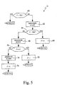
- the variance V of signal FC(i) is then calculated (block 30); the resulting value V is compared by central processing unit 150 with two threshold values TH1 , TH2 (where TH1 ⁇ TH2) to generate, if necessary, alarm signals (block 31) according to the procedure described in detail later on with reference to Figure 5; and block 31 then goes back to block 21 to continue monitoring with the next portion of signal s(t) .
- a revolution counter 1 is set to 1 (block 41); and signal s(t) is sampled at the previously defined frequency FS to obtain NJ points or samples T 1 (i) representing a synchronous vibratory time series relative to the sensor in question, to the respective shaft, and to each 1 -th revolution (block 42).
- the value of counter 1 in particular whether it is less than or equal to a predetermined value K1 , is determined (block 43); and, if counter 1 is less than or equal to K1 (performance of fewer than K1 iterations corresponding to the revolutions of the monitored shaft - YES output of block 43), the availability of the signal is determined by calculating (block 47) the sum ⁇ d of the samples acquired at the 1 -th revolution, according to the equation:
- a negative response NO output of block 49
- the signal is considered to exist, counter 1 is increased (block 50), and block 50 goes back to block 42 to acquire further NJ points relative to the next revolution.
- YES output of block 49 the signal is considered nonexistent and an alarm signal is generated (block 51); a check is made (block 52) to determine the presence of a substitute sensor (e.g.
- block 52 in the event of a positive response (YES output of block 52), block 52 goes back to block 21 in Figure 3 to repeat the procedure on the substitute sensor; and, in the absence of a substitute sensor, or if convergence is not reached even with the substitute sensor (NO output of block 52), the procedure is interrupted.
- Convergence of the averaging process is then determined by calculating a convergence value ⁇ given by the sum, over all the samples, of the absolute value of the difference between the actual mean value of each sample and the mean value calculated in a previous revolution (at distance 4) divided by the sum of the mean samples in the previous revolution considered (at distance 4), according to the equation: where T 1m (i) represents the i -th sample of the 1 -th iteration, and T 1m-4 (i) represents the i -th sample of the 1-4 -th iteration (block 56).
- the threshold comparison and alarm generating step in block 31 of Figure 3 is conveniently performed as described below with reference to Figure 5.
- V is compared with first threshold TH1 (block 60); if V ⁇ TH1 (YES output), block 60 goes back to block 21 in Figure 3 to continue monitoring with the next group of samples; conversely, if threshold TH1 has been exceeded (NO output of block 60), the event is memorized in event memory 153 (block 62) and V is compared with second threshold TH2 (block 64). If V ⁇ TH2 (YES output of block 64), variable F (initialized in block 20 of Figure 3 to memorize whether threshold TH2 has already been exceeded) is set to (or confirmed at) the first predetermined value, 0 in the example shown (block 66), and block 66 goes back to block 21 of Figure 3 to continue monitoring with the next group of samples.
- variable F is determined (block 70).
- F is set to a second predetermined value, e.g. 1, (block 72), and block 72 goes back to block 21 of Figure 3 to continue monitoring with the next group of samples.
- a pilot alarm signal is generated (block 74), variable F is again set to the first predetermined value (block 76), and block 76 goes back to block 21 of Figure 3 to continue monitoring with the next samples.
- the method provides for detecting any problems arising in modulation of the sensor signals.
Landscapes
- Engineering & Computer Science (AREA)
- General Engineering & Computer Science (AREA)
- Mechanical Engineering (AREA)
- Physics & Mathematics (AREA)
- Acoustics & Sound (AREA)
- General Physics & Mathematics (AREA)
- Aviation & Aerospace Engineering (AREA)
- Testing Of Devices, Machine Parts, Or Other Structures Thereof (AREA)
- Traffic Control Systems (AREA)
- Control Of Transmission Device (AREA)
Description
| Sensor | Pos. | Sensor | Pos. | Sensor | Pos. |
| 1 | 105 | 7 | 131 | 13 | 140 |
| 2 | 112 | 8 | 122 (front) | 14 | 136 |
| 3 | 117 | 9 | 122 (right) | 15 | 137 |
| 4 | 107 | 10 | 122 (left) | 16 | 108 |
| 5 | 114 | 11 | 126 | 17 | 139 |
| 6 | 119 | 12 | 139 |
where Z is the number of gear teeth.

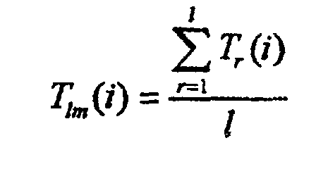
i.e. the mean value of each sample T1(i) over the 1 revolutions considered is calculated.

Claims (9)
- A method of monitoring a transmission assembly of a vehicle equipped with acceleration sensors, in particular a helicopter, comprising the steps of:a) acquiring a signal (s(t)) from an acceleration sensor;b) calculating the Hilbert transform (H[T'1m(i)]) of said signal;c) defining a complex signal (C1m(i)) having said signal as the real part and said Hilbert transform of said signal as the imaginary part;d) calculating the difference between the phase of said complex signal and a reference phase to obtain a phase signal (FC(i));e) calculating the variability of said phase signal to obtain a variability signal (V); andf) comparing said variability signal (V) with at least a first predetermined threshold (TH1, TH2).
- A method as claimed in claim 1, wherein said variability signal is the variance of said phase signal.
- A method as claimed in claims 1 or 2, wherein said steps a) to f) are repeated for a number of iterations.
- A method as claimed in any one of the foregoing claims, wherein said step of calculating said Hilbert transform is preceded by a step of sampling and filtering said signal.
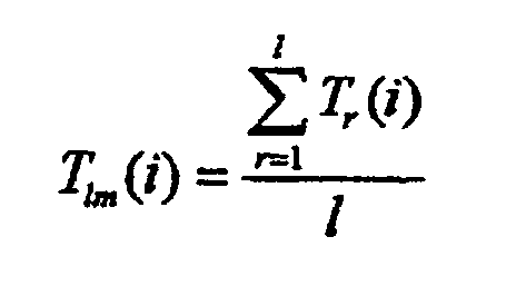
- A method as claimed in claim 4, wherein said step of sampling and filtering comprises the steps of:where T1(i) is said synchronous samples, 1 is a counter for counting the number of revolutions of said shaft, and N is the number of signal points.acquiring a number of synchronous samples T1(i) for each revolution of a shaft associated with said acceleration sensor; andcalculating an average time series T1m(i) according to the equation:i = 1...NJ
- A method as claimed in claim 5, wherein said step of sampling and filtering also comprises the step of filtering said average time series (T1m(i)) with a band-pass filter centered at a predetermined frequency, to obtain a filtered mean signal (T'1m(i)).
- A method as claimed in claims 5 or 6, wherein said step of calculating an average time series is preceded by a step of determining the presence of significant signal values.
- A method as claimed in one of the foregoing claims from 5 to 7, wherein said step of calculating an average time series is followed by a step of determining convergence of said average time series.
- A method as claimed in any one of the foregoing claims, wherein said step of comparing said variability signal also comprises the step of comparing said variability signal with a second threshold.
Applications Claiming Priority (2)
| Application Number | Priority Date | Filing Date | Title |
|---|---|---|---|
| IT97TO000592A IT1293410B1 (en) | 1997-07-04 | 1997-07-04 | METHOD OF SURVEILLANCE OF A TRANSMISSION UNIT IN A VEHICLE EQUIPPED WITH ACCELEROMETRIC SENSORS, ESPECIALLY IN A HELICOPTER. |
| ITTO970592 | 1997-07-04 |
Publications (3)
| Publication Number | Publication Date |
|---|---|
| EP0889316A2 EP0889316A2 (en) | 1999-01-07 |
| EP0889316A3 EP0889316A3 (en) | 1999-05-19 |
| EP0889316B1 true EP0889316B1 (en) | 2003-02-19 |
Family
ID=11415835
Family Applications (1)
| Application Number | Title | Priority Date | Filing Date |
|---|---|---|---|
| EP98112408A Expired - Lifetime EP0889316B1 (en) | 1997-07-04 | 1998-07-03 | Method of monitoring a transmission assembly of a vehicle equipped with acceleration sensors, in particular a helicopter |
Country Status (5)
| Country | Link |
|---|---|
| US (1) | US6016993A (en) |
| EP (1) | EP0889316B1 (en) |
| JP (1) | JP4071363B2 (en) |
| DE (1) | DE69811434T2 (en) |
| IT (1) | IT1293410B1 (en) |
Cited By (3)
| Publication number | Priority date | Publication date | Assignee | Title |
|---|---|---|---|---|
| US7925392B2 (en) | 2002-04-23 | 2011-04-12 | Lord Corporation | Aircraft vehicular propulsion system monitoring device and method |
| EP4091945A1 (en) | 2021-05-18 | 2022-11-23 | Leonardo S.p.a. | Method and system for detecting anomalies relating to components of a transmission system of an aircraft, in particular a helicopter |
| US11543269B2 (en) | 2020-01-27 | 2023-01-03 | Temposonics GmbH & Co. KG | Target detection in magnetostrictive sensors using a target frequency range |
Families Citing this family (15)
| Publication number | Priority date | Publication date | Assignee | Title |
|---|---|---|---|---|
| FR2803036B1 (en) | 1999-12-23 | 2002-10-11 | Snecma | DETECTION OF DAMAGE TO PARTS OF AN ENGINE |
| US6954685B2 (en) | 2002-04-23 | 2005-10-11 | Lord Corporation | Aircraft vehicular propulsion system monitoring device and method |
| DE10303877A1 (en) * | 2003-01-31 | 2004-08-12 | Fag Kugelfischer Ag | Method for determining structure-borne noise events in a rolling bearing |
| DE102005028488A1 (en) * | 2005-03-01 | 2006-09-07 | Siemens Ag | Engineering system |
| US8602166B2 (en) * | 2006-01-05 | 2013-12-10 | Sikorsky Aircraft Corporation | Secondary lubrication system with injectable additive |
| JP4112594B2 (en) * | 2006-07-27 | 2008-07-02 | ファナック株式会社 | Reduction gear abnormality diagnosis method and reduction gear abnormality diagnosis device |
| ATE533929T1 (en) * | 2007-01-19 | 2011-12-15 | Sikorsky Aircraft Corp | LUBRICANT SYSTEM WITH EXTENDED LOL OPERATION (LOL - LOSS OF LUBRICANT) |
| GB2488130B (en) * | 2011-02-16 | 2017-05-17 | Cnr Services Int Ltd | Helicopter shaft alignment |
| DE102015210695B3 (en) * | 2015-06-11 | 2016-09-29 | Schaeffler Technologies AG & Co. KG | Device and method for monitoring a vibration-excited component |
| WO2017147332A1 (en) * | 2016-02-24 | 2017-08-31 | Sunpower Corporation | Solar panel |
| DE102016221127B4 (en) * | 2016-10-26 | 2022-10-27 | Zf Friedrichshafen Ag | Propulsion arrangement for a helicopter |
| CN108152033B (en) * | 2017-12-14 | 2019-07-23 | 东华大学 | A sparse separation model-based composite weak fault diagnosis method for gearboxes |
| FR3083861B1 (en) | 2018-07-12 | 2020-10-16 | Airbus Helicopters | METHOD OF ANALYSIS OF A VIBRATORY SIGNAL RESULTING FROM A ROTATION OF AT LEAST ONE MOVABLE PART BELONGING TO A ROTATING MECHANISM |
| CN110887660B (en) * | 2019-11-12 | 2021-02-26 | 重庆长安新能源汽车科技有限公司 | Main impact point detection method for reducer meshing backlash impact abnormal sound |
| CN111216884B (en) * | 2020-02-12 | 2022-11-15 | 西安爱生技术集团公司 | Automatic control device for engagement of box type launching unmanned aerial vehicle engine and propeller |
Family Cites Families (7)
| Publication number | Priority date | Publication date | Assignee | Title |
|---|---|---|---|---|
| US3699806A (en) * | 1967-07-14 | 1972-10-24 | Bjorn Weichbrodt | Early detection of damage to machine elements in rolling engagement |
| US4654836A (en) * | 1982-10-18 | 1987-03-31 | Texas Instruments Incorporated | Seismic vibrator source having improved phase detector |
| GB2234411A (en) * | 1989-07-03 | 1991-01-30 | Marconi Instruments Ltd | Integrated circuit for digital demodulation |
| US5210704A (en) * | 1990-10-02 | 1993-05-11 | Technology International Incorporated | System for prognosis and diagnostics of failure and wearout monitoring and for prediction of life expectancy of helicopter gearboxes and other rotating equipment |
| US5501105A (en) * | 1991-10-02 | 1996-03-26 | Monitoring Technology Corp. | Digital signal processing of encoder signals to detect resonances in rotating machines |
| US5365787A (en) * | 1991-10-02 | 1994-11-22 | Monitoring Technology Corp. | Noninvasive method and apparatus for determining resonance information for rotating machinery components and for anticipating component failure from changes therein |
| FR2683204B1 (en) * | 1991-10-30 | 1997-04-25 | Aerospatiale | SYSTEM FOR BACKING UP A MULTIPLIER / REDUCER MECHANICAL ASSEMBLY, PARTICULARLY OF THE HELICOPTER "TRANSMISSION" TYPE, IN CASE OF LOSS OF LUBRICATING OIL. |
-
1997
- 1997-07-04 IT IT97TO000592A patent/IT1293410B1/en active IP Right Grant
-
1998
- 1998-07-03 DE DE69811434T patent/DE69811434T2/en not_active Expired - Lifetime
- 1998-07-03 EP EP98112408A patent/EP0889316B1/en not_active Expired - Lifetime
- 1998-07-06 US US09/110,305 patent/US6016993A/en not_active Expired - Lifetime
- 1998-07-06 JP JP19026998A patent/JP4071363B2/en not_active Expired - Fee Related
Cited By (3)
| Publication number | Priority date | Publication date | Assignee | Title |
|---|---|---|---|---|
| US7925392B2 (en) | 2002-04-23 | 2011-04-12 | Lord Corporation | Aircraft vehicular propulsion system monitoring device and method |
| US11543269B2 (en) | 2020-01-27 | 2023-01-03 | Temposonics GmbH & Co. KG | Target detection in magnetostrictive sensors using a target frequency range |
| EP4091945A1 (en) | 2021-05-18 | 2022-11-23 | Leonardo S.p.a. | Method and system for detecting anomalies relating to components of a transmission system of an aircraft, in particular a helicopter |
Also Published As
| Publication number | Publication date |
|---|---|
| DE69811434D1 (en) | 2003-03-27 |
| US6016993A (en) | 2000-01-25 |
| DE69811434T2 (en) | 2003-08-14 |
| IT1293410B1 (en) | 1999-03-01 |
| EP0889316A2 (en) | 1999-01-07 |
| JPH11124099A (en) | 1999-05-11 |
| ITTO970592A1 (en) | 1999-01-04 |
| EP0889316A3 (en) | 1999-05-19 |
| JP4071363B2 (en) | 2008-04-02 |
Similar Documents
| Publication | Publication Date | Title |
|---|---|---|
| EP0889316B1 (en) | Method of monitoring a transmission assembly of a vehicle equipped with acceleration sensors, in particular a helicopter | |
| EP0889314B1 (en) | Method of monitoring a transmission assembly of a vehicle equipped with acceleration sensors, in particular a helicopter | |
| EP0889315B1 (en) | Method of monitoring a transmission assembly of a vehicle equipped with acceleration sensors, in particular a helicopter | |
| EP0899553B1 (en) | Method of monitoring an epicyclic gear assembly equipped with acceleration sensors in a vehicle, in particular a helicopter | |
| US7430483B2 (en) | Method and apparatus for diagnosing a mechanism | |
| DE69421393T2 (en) | METHOD AND DEVICE FOR DETECTING AND ANALYZING FAULTS IN BEARINGS AND OTHER SLIDING ROTATING COMPONENTS | |
| EP0889313B1 (en) | A method of monitoring a transmission assembly of a vehicle equipped with acceleration sensors, in particular a helicopter | |
| US20040200283A1 (en) | Synchronous averaging of epicyclic sun gear vibration | |
| US6298725B1 (en) | Method for the separation of epicyclic planet gear vibration signatures | |
| CN109682597A (en) | A kind of gear-box vibration signal processing and analysis method | |
| EP1300668A1 (en) | Method for the separation of epicyclic planet gear vibration signatures | |
| Wang et al. | A model-based gear diagnostic technique | |
| CN115165355B (en) | Method and system for detecting modulation sideband frequency of gears in complex transmission systems | |
| Bechhoefer | Condition monitoring of a cycloid gearbox | |
| Vaerenberg et al. | Detecting planet gear crack propagation using FRESH filters | |
| Forrester et al. | Analysis of epicyclic gearbox vibration | |
| Tsutsui et al. | Relationship Between Rotational Angle and Time-Synchronous-Averaged Meshing | |
| Ma et al. | A new approach to gear vibration demodulation and its application to defect detection | |
| Wang et al. | A novel technique of crack detection for helicopter main gearbox planet carrier | |
| CN118067391A (en) | A method for separating torsional vibration signals for planetary gear fault diagnosis | |
| Abidat et al. | COMPARY STUDY OF EFFECTIVE AND SENSITIVE VIBRATION PROCESSING TECHNIQUES FOR LOCAL FAULT DETECTION IN THE GEARS IN A GEARBOX | |
| Wang | Comb-Filtering-Based Signal Reconstruction for Bearing Fault Detection |
Legal Events
| Date | Code | Title | Description |
|---|---|---|---|
| PUAI | Public reference made under article 153(3) epc to a published international application that has entered the european phase |
Free format text: ORIGINAL CODE: 0009012 |
|
| AK | Designated contracting states |
Kind code of ref document: A2 Designated state(s): DE FR GB |
|
| AX | Request for extension of the european patent |
Free format text: AL;LT;LV;MK;RO;SI |
|
| PUAL | Search report despatched |
Free format text: ORIGINAL CODE: 0009013 |
|
| AK | Designated contracting states |
Kind code of ref document: A3 Designated state(s): AT BE CH CY DE DK ES FI FR GB GR IE IT LI LU MC NL PT SE |
|
| AX | Request for extension of the european patent |
Free format text: AL;LT;LV;MK;RO;SI |
|
| 17P | Request for examination filed |
Effective date: 19991022 |
|
| AKX | Designation fees paid |
Free format text: DE FR GB |
|
| RAP1 | Party data changed (applicant data changed or rights of an application transferred) |
Owner name: AGUSTA S.P.A. |
|
| GRAG | Despatch of communication of intention to grant |
Free format text: ORIGINAL CODE: EPIDOS AGRA |
|
| 17Q | First examination report despatched |
Effective date: 20020529 |
|
| GRAG | Despatch of communication of intention to grant |
Free format text: ORIGINAL CODE: EPIDOS AGRA |
|
| GRAH | Despatch of communication of intention to grant a patent |
Free format text: ORIGINAL CODE: EPIDOS IGRA |
|
| GRAH | Despatch of communication of intention to grant a patent |
Free format text: ORIGINAL CODE: EPIDOS IGRA |
|
| GRAA | (expected) grant |
Free format text: ORIGINAL CODE: 0009210 |
|
| AK | Designated contracting states |
Designated state(s): DE FR GB |
|
| REG | Reference to a national code |
Ref country code: GB Ref legal event code: FG4D |
|
| REF | Corresponds to: |
Ref document number: 69811434 Country of ref document: DE Date of ref document: 20030327 Kind code of ref document: P |
|
| ET | Fr: translation filed | ||
| PLBE | No opposition filed within time limit |
Free format text: ORIGINAL CODE: 0009261 |
|
| STAA | Information on the status of an ep patent application or granted ep patent |
Free format text: STATUS: NO OPPOSITION FILED WITHIN TIME LIMIT |
|
| 26N | No opposition filed |
Effective date: 20031120 |
|
| REG | Reference to a national code |
Ref country code: FR Ref legal event code: PLFP Year of fee payment: 18 |
|
| PGFP | Annual fee paid to national office [announced via postgrant information from national office to epo] |
Ref country code: GB Payment date: 20150708 Year of fee payment: 18 Ref country code: DE Payment date: 20150707 Year of fee payment: 18 |
|
| PGFP | Annual fee paid to national office [announced via postgrant information from national office to epo] |
Ref country code: FR Payment date: 20150709 Year of fee payment: 18 |
|
| REG | Reference to a national code |
Ref country code: DE Ref legal event code: R082 Ref document number: 69811434 Country of ref document: DE Representative=s name: ZENZ PATENTANWAELTE PARTNERSCHAFT MBB, DE |
|
| REG | Reference to a national code |
Ref country code: DE Ref legal event code: R119 Ref document number: 69811434 Country of ref document: DE |
|
| GBPC | Gb: european patent ceased through non-payment of renewal fee |
Effective date: 20160703 |
|
| PG25 | Lapsed in a contracting state [announced via postgrant information from national office to epo] |
Ref country code: DE Free format text: LAPSE BECAUSE OF NON-PAYMENT OF DUE FEES Effective date: 20170201 Ref country code: FR Free format text: LAPSE BECAUSE OF NON-PAYMENT OF DUE FEES Effective date: 20160801 |
|
| REG | Reference to a national code |
Ref country code: FR Ref legal event code: ST Effective date: 20170331 |
|
| PG25 | Lapsed in a contracting state [announced via postgrant information from national office to epo] |
Ref country code: GB Free format text: LAPSE BECAUSE OF NON-PAYMENT OF DUE FEES Effective date: 20160703 |