EP0892259B1 - Dispositif pour mesurer la pression de pneumatiques des véhicules roulants - Google Patents
Dispositif pour mesurer la pression de pneumatiques des véhicules roulants Download PDFInfo
- Publication number
- EP0892259B1 EP0892259B1 EP98112442A EP98112442A EP0892259B1 EP 0892259 B1 EP0892259 B1 EP 0892259B1 EP 98112442 A EP98112442 A EP 98112442A EP 98112442 A EP98112442 A EP 98112442A EP 0892259 B1 EP0892259 B1 EP 0892259B1
- Authority
- EP
- European Patent Office
- Prior art keywords
- individual
- measuring
- tyre
- vehicle
- sensor arrangement
- Prior art date
- Legal status (The legal status is an assumption and is not a legal conclusion. Google has not performed a legal analysis and makes no representation as to the accuracy of the status listed.)
- Expired - Lifetime
Links
Images


Classifications
-
- G—PHYSICS
- G01—MEASURING; TESTING
- G01L—MEASURING FORCE, STRESS, TORQUE, WORK, MECHANICAL POWER, MECHANICAL EFFICIENCY, OR FLUID PRESSURE
- G01L17/00—Devices or apparatus for measuring tyre pressure or the pressure in other inflated bodies
- G01L17/005—Devices or apparatus for measuring tyre pressure or the pressure in other inflated bodies using a sensor contacting the exterior surface, e.g. for measuring deformation
Definitions
- the invention relates to an arrangement according to the preamble of claim 1.
- a measuring arrangement is known from vehicles in US-A-4,630,470. At the individual wheels are artificially stimulated to vibrate, of which a frequency spectrum is recorded. Through a A comparison of the spectra of the individual wheels with each other is intended Wheel whose pressure differs from that of the other is recognized are at a changed frequency spectrum. This arrangement assumes that the majority of the wheels of a vehicle with the correct tire pressure is provided; otherwise wheels are included Underpressure or overpressure not recognizable.
- the invention is therefore based on the object of a measuring arrangement to create the exact tire footprint to determine with the isobars of each wheel, to represent them arithmetically and to compare with those of the other bikes. For the vehicle speed must perform this measurement and calculation process and a large number per wheel, e.g. at least 10 rollover segments recorded become.
- the data acquisition system stores the individual tire contact patches immediately between and compares special features of the isobar course with the imprint images of the other wheels of a vehicle.
- the isobar images of heavy traffic the biggest road damage and in general also caused the most serious accidents regardless of the vehicle and / or Tire brand as well as of the vehicle or tire type, very much
- the isobaric images can be similar and comparable also with the image of one stored in the data acquisition system "Normal pressure" isobars for the respective vehicle type be compared, for example, from the same time recorded axle load and / or the number of rolling over the system Wheels or axles can be closed.
- a pictorial representation or an elimination signal are immediate available after crossing, processing speed must be so high that vehicles with faulty tire pressures can be eliminated from normal road traffic; this is how traffic is monitored according to tire pressure conditions possible.
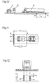
- FIG. 1 shows a measuring rail 12 according to the invention with a Row arrangement of force measuring elements 1,2,3..n, shown, whose width with B and their length, viewed in the direction of travel R, are denoted by L.
- Each force measuring element 1,2,3 has its own Crystal arrangement 5 provided as a sensor, which upon exposure a force F a proportional electrical signal into a Outputs signal line 6.
- the individual Cell 1, 2, 3 are saw sections of a metal profile, consisting of force inlet flange, pipe part 11 and Force support flange.
- the crystal arrangement 5 is in the tube part 11 housed under mechanical preload in a plastic spout 9.
- the single force measuring elements 1,2,3 .. are with a sand-epoxy infusion plate 10, the total after Installation can be ground with the street surface.
- the Spaces S between the individual force measuring elements 1,2,3 kept as small as possible and cast with polyurethane casting resin.
- the total length of a measuring rail 12 can e.g. 1 m or more be; it has a width B of a single element of 20 mm about 50 and more force measuring elements 1,2,3 on the mounting rail 8 are mounted.
- the fully assembled measuring rail 12 is installed still with side pad 15, consisting of casting compound and rubber band 16 provided and then in the prepared street groove 17 with Casting compound 18 cast.
- the dimensions of the street groove 17 with respect to depth T and width W according to the invention are approximately 1: 1, which means that a solid anchoring is guaranteed even with rolling traffic becomes.
- the upper part E of the measuring rail 12 represents the force introduction part, the middle M the signal conversion part and V the anchoring part
- the surface part O is made by grinding into a flat surface brought to the street surface.
- the tire 19 is in the making to drive onto the measuring rail 12.
- the rollover process of the tire 19 results in a rollover signal Si 1 , Si 2 , Si 3 ... in each individual force measuring element 1 , 2 , 3 , proportional to the force F over time t.
- These rollover signals and the vehicle speed v form the main parameters of the subsequent computer work in the data acquisition system.
- Fig. 3 shows the tire 19 in elevation just above the built-in Measuring bar 12.
- FIG. 4 shows FIG. 3 in plan view above the measuring rail 12.
- the tire contact area 20 is usually wider than the tire width b 1 .
- the measuring rail 12 with the individual force measuring elements 1, 2, 3 and their width B divides the tire contact area 20 into at least 8 to 10 subsections 21, which enables a satisfactory resolution of the subsequent computing power.
- FIG. 5 shows the measuring rail 12 in plan with the individual force measuring elements 1, 2, 3, superimposed by an average tire profile 22, shown in the direction of travel R.
- at least three partial areas T f1 , T f2 , T f3 of the tire profile 22 on one Individual force measuring element 1, 2, 3 rests, their lengths L should be at least about 50 mm.
- the data calculated in this way can be used to assess the tire pressure different evaluation methods can be selected.
- an appropriate Programming of data acquisition can be done, for example Absolute values of the respective tire pressure from the with With the help of the previously laid contact rail certain vehicle speed and the lengths lx of the recorded tire contact patches determine.
- Fig. 8 shows a rear axle of a truck with two double tires each each via measuring rails 12.
- FIG. 9 shows the peak values of the tires shown in FIG. 8 when the measuring rails 12 roll over.
- the maximum values of the individual roll signals Si 1 , Si 2 , Si 3 which are the sum curves 46 for negative pressure, 45 for normal pressure and 47, are sufficient result for overpressure and can be easily recognized by calculation. From the surfaces of curves 45 to 47, the axle loads, separated on the left and right, can be calculated immediately by the computer.
- Fig. 10 shows in the application example where a truck 50 in a Petrol station drives in. After reaching the tap 51 is on the display panel 52 contains the information of the measuring rail 12 that has been rolled over and the contact rail K, which is let in a few meters ahead displayed.
- Fig. 11 shows the floor plan where the measuring rail 12 in the middle of the lane divided and based on the direction of travel 12 l of the left Half of the lane and 12 r assigned to the right half of the lane is; this in turn enables the tire conditions to be recorded at the same time, as well as the summation of the axle weights of the left and right vehicle halves.
- any overweights as well as the load distribution can be checked immediately. So that results an interesting additional range of services the petrol station owner. Similarly valuable, automated data can become important at truck terminals.
- the arrangement according to the invention can thus make important contributions to Bring increased operational safety in vehicle traffic by inadmissible tire pressure conditions recognizable in rolling traffic and be made separable.
- the invention also enables automated additional security check in vehicle terminals or at taps.
Landscapes
- Chemical & Material Sciences (AREA)
- Analytical Chemistry (AREA)
- Physics & Mathematics (AREA)
- General Physics & Mathematics (AREA)
- Force Measurement Appropriate To Specific Purposes (AREA)
Claims (8)
- Aménagement de capteurs destiné à être installé dans les chaussées à fin de saisie des pressions des pneumatiques des roues (19) d'un véhicule (50, 60) durant le roulage normal, constitué d'une rangée de capteurs individuels comprenant chacun une bride d'introduction de force et, opposée à celle-ci, une bride d'appui, caractérisé en ce que l'aménagement de mesure se compose d'un rail de contact (K) installé dans le sens du roulage avant le rail de mesure (12) et d'un dispositif de saisie des données (52) séparé, le rail de mesure (12) étant constitué d'éléments de mesure (1, 2, 3) rectangulaires dont la longueur (L) dans le sens du roulage est un multiple de leur largeur et qui sont montés sur un rail de montage (8) pouvant être ancré dans une rainure (17) de la chaussée de telle manière que la profondeur (T) et la largeur (w) de la rainure (17) aient à peu près les mêmes dimensions.
- Aménagement de capteur selon revendication 1 caractérisé en ce que chaque élément de mesure (1, 2, 3) comporte une plaque de recouvrement (10) constituée d'un mélange sable-epoxy, l'interstice (S) par rapport à la plaque de recouvrement contigüe étant rempli d'une masse plastique élastique.
- Aménagement de capteurs selon revendications 1 ou 2 caractérisé en ce que la largeur des éléments individuels (1, 2, 3) est de 20 mm au maximum et que l'écart par rapport à l'élément contigüe est au maximum de 0,5 mm.
- Aménagement de capteurs selon l'une des revendications 1 à 3, installé à l'entrée de stations-service, caractérisé en ce que l'aménagement est conçu de telle sorte qu'en utilisation après l'arrêt pour ravitaillement en carburant l'état de gonflage des pneumatiques est simultanément affiché optiquement, ainsi que, le cas échéant, l'indication du pneu dont le gonflage n'est pas correct.
- Aménagement de capteurs selon l'une des revendications 1 à 3, installé à l'entrée ou à la sortie de gares routières ou de dépots caractérisé en ce que l'aménagement est conçu de telle sorte qu'en utilisation un affichage optique et un enregistrement automatique de surveillance des véhicules quant au respect des valeurs de gonflage des pneumatiques soient réalisés.
- Aménagement de capteurs selon l'une des revendications 1 à 5 caractérisé en ce que l'installation de saisie des données est conçue de telle sorte qu'en utilisation, simultanément à l'affichage de la répartition des pressions de gonflage des pneus, soit additionnées les forces totales des diverses roues de la moitié gauche et de la moitié droite du véhicule afin de détecter les décalages éventuels des charges.
- Aménagement de capteurs selon l'une des revendications de brevet 1 à 6 caractérisé en ce qu'en utilisation, l'installation de saisie des données est complètée d'un dispositif pour additionner les forces d'appui de tous les pneus et de les afficher et donc de saisir le poids total du véhicule permettant ainsi l'enregistrement automatique de l'état de fonctionnement du véhicule quant à la pression des pneus, à la symétrie du chargement et du poids total en charge, ces données pouvant servir de références en cas de dommages.
- Procédé pour la saisie de la pression de gonflage des différentes roues (19) d'un véhicule (50, 60) durant le roulage à l'aide de l'aménagement de capteur selon l'une des revendications 1 à 3 caractérisé par les séquences suivantes:
Saisie de la vitesse du véhicule par mesure du temps après contact de chaque roue avec le rail de contact (K) disposé à une certaine distance (D), par exemple, 200 cm avant le rail de mesure;Saisie au moyen d'une multitude de capteurs disposés sur la largeur (b1) de la roue de la sollicitation en pression engendrée par chaque roue passant par dessus le rail de mesure (12) en fonction du temps;Détermination de la forme et de l'intensité des profils de répartition de pression sur la largeur (b1) de chaque roue (19) durant son passage en roulant par dessus le rail de mesure (12) et, par la même, calcul de la surface d'appui du pneu (20) et de la pression moyenne de chaque roue (19);Comparaison entre eux des profils de répartition de pression relevés sur les différentes roues et, le cas échéant, avec un profil de pression de référence normal correspondant au type de véhicule et de pneu.
Applications Claiming Priority (3)
| Application Number | Priority Date | Filing Date | Title |
|---|---|---|---|
| CH1738/97 | 1997-07-16 | ||
| CH173897 | 1997-07-16 | ||
| CH01738/97A CH692965A5 (de) | 1997-07-16 | 1997-07-16 | Anordnung zum Messen des Reifendrucks von rollenden Fahrzeugen. |
Publications (2)
| Publication Number | Publication Date |
|---|---|
| EP0892259A1 EP0892259A1 (fr) | 1999-01-20 |
| EP0892259B1 true EP0892259B1 (fr) | 2001-09-26 |
Family
ID=4217431
Family Applications (1)
| Application Number | Title | Priority Date | Filing Date |
|---|---|---|---|
| EP98112442A Expired - Lifetime EP0892259B1 (fr) | 1997-07-16 | 1998-07-06 | Dispositif pour mesurer la pression de pneumatiques des véhicules roulants |
Country Status (4)
| Country | Link |
|---|---|
| US (1) | US5942681A (fr) |
| EP (1) | EP0892259B1 (fr) |
| CH (1) | CH692965A5 (fr) |
| DE (1) | DE59801565D1 (fr) |
Families Citing this family (42)
| Publication number | Priority date | Publication date | Assignee | Title |
|---|---|---|---|---|
| GB9709645D0 (en) * | 1997-05-14 | 1997-07-02 | Sun Electric Uk Ltd | Tyre pressure determination |
| EP0997713A1 (fr) | 1998-10-29 | 2000-05-03 | K.K. Holding AG | Système de surveillance de trafic routier |
| DE19851563A1 (de) * | 1998-11-09 | 2000-05-18 | Bosch Gmbh Robert | Automatisches Fahrzeug-Reifendruckmeß/-einstellsystem und Fahrzeug-Reifendruckmeß/-einstellverfahren |
| FR2812085B1 (fr) * | 2000-07-20 | 2002-10-25 | Dufournier Technologies S A S | Dispositif et procede de cartographie des effets au sol du passage d'un vehicule |
| US8266465B2 (en) | 2000-07-26 | 2012-09-11 | Bridgestone Americas Tire Operation, LLC | System for conserving battery life in a battery operated device |
| US7161476B2 (en) | 2000-07-26 | 2007-01-09 | Bridgestone Firestone North American Tire, Llc | Electronic tire management system |
| TW467290U (en) * | 2001-02-19 | 2001-12-01 | Shu-Chin Wu | Apparatus for detecting low tire pressure of car tire |
| US6606902B2 (en) | 2001-07-09 | 2003-08-19 | The Goodyear Tire & Rubber Company | Method of improving steering performance robustness utilizing stiffness non-uniformity in tire/wheel |
| US6672148B2 (en) | 2001-07-09 | 2004-01-06 | The Goodyear Tire & Rubber Company | Method of improving steering performance robustness utilizing mass non-uniformity in tire/wheel |
| US6668635B2 (en) | 2001-07-09 | 2003-12-30 | The Goodyear Tire & Rubber Company | Method of improving steering performance robustness utilizing dimensional non-uniformity in tire/wheel |
| DE20200489U1 (de) | 2002-01-10 | 2002-05-29 | VELOMAT Messelektronik GmbH, 01917 Kamenz | Vorrichtung zur Bestimmung des Reifeninnendrucks |
| US6823728B1 (en) | 2002-03-12 | 2004-11-30 | Elwood E. Barnes | Systems and methods for measurement of tire pressure |
| US7574293B2 (en) * | 2004-02-19 | 2009-08-11 | Johnson Controls Technology Company | System and method for identifying tire position on a vehicle |
| GB0415258D0 (en) * | 2004-07-07 | 2004-08-11 | Wheelright Ltd | Vehicle tyre checking system |
| US7969293B2 (en) * | 2008-10-13 | 2011-06-28 | The Goodyear Tire & Rubber Company | Integrated read station for a wheel-mounted vehicle |
| GB2470903B (en) | 2009-06-08 | 2013-01-02 | Wheelright Ltd | Vehicle tyre inflation checking system |
| US20110011180A1 (en) * | 2009-07-17 | 2011-01-20 | John Wilson | Sensor housing assembly facilitating sensor installation, replacement, recovery and reuse |
| US20110148593A1 (en) * | 2009-12-17 | 2011-06-23 | Robert Leon Benedict | Method for reading a vehicle tag within a read station |
| US9135479B2 (en) * | 2009-12-17 | 2015-09-15 | The Goodyear Tire & Rubber Company | Antenna assembly for a tag reader |
| NL2004500C2 (nl) † | 2010-04-01 | 2011-10-04 | Konink Bam Groep Nv | Systeem en werkwijze voor het bepalen van aslast en/of totaalgewicht van een voertuig, alsmede sensorinrichting. |
| CH705261A1 (de) | 2011-07-07 | 2013-01-15 | Kistler Holding Ag | Verfahren zum Verbinden einer Membran an ein Sensorgehäuse. |
| FR2978563B1 (fr) * | 2011-07-29 | 2014-03-21 | Yzatec | Capteur de passage de vehicules roulants a detecteurs piezo-electriques juxtaposes independants |
| GB2494618B (en) | 2011-08-22 | 2018-03-21 | Wheelright Ltd | Vehicle tyre pressure measurement |
| CN102374889A (zh) * | 2011-09-22 | 2012-03-14 | 深圳思量微系统有限公司 | 一种具有车辆胎压监测功能的动态称重系统 |
| CH705675A1 (de) | 2011-10-20 | 2013-04-30 | Kistler Holding Ag | Hohlprofil-Aufnehmer. |
| CH705762A1 (de) | 2011-11-04 | 2013-05-15 | Kistler Holding Ag | Verfahren zum Wiegen eines Fahrzeuges, sowie Messeinrichtung und Messkette hierfür. |
| CH705783A1 (de) | 2011-11-18 | 2013-05-31 | Kistler Holding Ag | WIM Hohlprofil. |
| CH706013A1 (de) * | 2012-01-11 | 2013-07-15 | Kistler Holding Ag | Sensorpaket für WIM Sensor und WIM Sensor. |
| DE102012205495A1 (de) | 2012-04-04 | 2013-10-10 | Robert Bosch Gmbh | Verfahren und Vorrichtung zur Reifendruckprüfung |
| DE102012205694A1 (de) | 2012-04-05 | 2013-10-10 | Robert Bosch Gmbh | Verfahren und Vorrichtung zur Reifendruckprüfung |
| DE102012210015A1 (de) | 2012-06-14 | 2013-12-19 | Robert Bosch Gmbh | Vorrichtung und Verfahren zur Reifendruckprüfung |
| US9429463B2 (en) | 2013-03-04 | 2016-08-30 | International Road Dynamics, Inc. | System and method for measuring moving vehicle information using electrical time domain reflectometry |
| US9183423B2 (en) | 2013-07-26 | 2015-11-10 | The Goodyear Tire & Rubber Company | Drive-over stand and antenna assembly |
| FR3016231B1 (fr) * | 2014-01-08 | 2016-02-12 | Yzatec | Detecteur routier piezoelectrique multizone a densite variable d'elements piezoelectriques |
| EP3029435B1 (fr) * | 2014-12-01 | 2018-02-28 | HAENNI Instruments AG | Dispositif de capteur de force destiné à l'enregistrement du poids d'un véhicule |
| FR3030374B1 (fr) * | 2014-12-17 | 2017-01-13 | Michelin & Cie | Procede de detection et d'alerte de l'etat de sous-gonflage d'un pneumatique |
| FR3030742A1 (fr) * | 2014-12-17 | 2016-06-24 | Michelin & Cie | Systeme et procede d'evaluation de l'aire de contact d'un pneumatique |
| CN106441699B (zh) * | 2016-08-30 | 2022-05-17 | 重庆长安民生物流股份有限公司 | 一种汽车轮胎气压检测装置 |
| EP3559614B1 (fr) * | 2016-12-21 | 2020-11-25 | Kistler Holding AG | Arrangement d'un transducteur à incorporer dans une route et procédé de montage dans la route |
| KR102677243B1 (ko) * | 2019-05-07 | 2024-06-20 | 키스틀러 홀딩 아게 | 트랜스듀서 조립체 |
| HUE062097T2 (hu) * | 2019-12-16 | 2023-09-28 | Kistler Holding Ag | WIM-erõátalakító és egy ilyen WIM-erõátalakító házprofilja |
| JP2024035795A (ja) * | 2022-09-02 | 2024-03-14 | キストラー ホールディング アクチエンゲゼルシャフト | Wimセンサを有するwimシステム |
Family Cites Families (3)
| Publication number | Priority date | Publication date | Assignee | Title |
|---|---|---|---|---|
| US4630470A (en) * | 1984-11-16 | 1986-12-23 | The United States Of America As Represented By The Secretary Of The Army | Remote sensing of vehicle tire pressure |
| US5396817A (en) * | 1991-11-29 | 1995-03-14 | Exxon Research And Engineering Co. | Tire inflation and velocity sensor |
| CH689599A5 (de) * | 1993-11-23 | 1999-06-30 | Kk Holding Ag | Aufnehmer-Anordnung zum Einbau in Fahrbahnen zwecks Erfassung der Gewichte und/oder der fahrdynamischen Reaktionen von Fahrzeugrädern. |
-
1997
- 1997-07-16 CH CH01738/97A patent/CH692965A5/de not_active IP Right Cessation
-
1998
- 1998-07-06 DE DE59801565T patent/DE59801565D1/de not_active Expired - Fee Related
- 1998-07-06 EP EP98112442A patent/EP0892259B1/fr not_active Expired - Lifetime
- 1998-07-15 US US09/115,671 patent/US5942681A/en not_active Expired - Fee Related
Also Published As
| Publication number | Publication date |
|---|---|
| US5942681A (en) | 1999-08-24 |
| DE59801565D1 (de) | 2001-10-31 |
| EP0892259A1 (fr) | 1999-01-20 |
| CH692965A5 (de) | 2002-12-31 |
Similar Documents
| Publication | Publication Date | Title |
|---|---|---|
| EP0892259B1 (fr) | Dispositif pour mesurer la pression de pneumatiques des véhicules roulants | |
| EP0280785B2 (fr) | Banc d'essai des freins de véhicules, en particulier d'automobiles à dispositif d'anti-blocage des freins | |
| EP2109754B1 (fr) | Dispositif de mesure de la géométrie d'un train de roulement | |
| EP2321618A1 (fr) | Dispositif et procédé de détermination et de réglage de la géométrie d'un châssis de véhicule à moteur | |
| EP2834611B1 (fr) | Procédé et dispositif pour contrôler la pression de gonflage | |
| EP1293362A2 (fr) | Procédé pour déterminer la pression d'air et la charge de roue de pneumatiques de véhicule | |
| EP0923719B1 (fr) | Dispositif pour le controle de vehicules | |
| DE3514759A1 (de) | Einrichtung zur vermessung der achsgeometrie an den radachsen von kraftfahrzeugen bei drehenden raedern | |
| EP3548852B1 (fr) | Procédé et dispositif de détection du poids d'une charge se déplaçant sur une balance | |
| DE69419597T2 (de) | Vorrichtung zur messung und verfahren zur kraftfahrzeugstabilitätsregelung | |
| EP0866323A2 (fr) | Platforme de mesure pour la surveillance du poids et du système de freinage | |
| EP1154230B1 (fr) | Dispositif et méthode de mesure du châssis d'un véhicule | |
| DE4124555C2 (de) | Verfahren und Vorrichtung zum Messen der Radausrichtung von selbstfahrenden Fahrzeugen | |
| WO2007141077A1 (fr) | Procédé et véhicule de mesure pour déterminer les propriétés objectives des pneumatiques sur la surface d'une chaussée | |
| DE2952730C2 (de) | Zusatzeinrichtung für einen Rollenprüfstand für Kraftfahrzeuge | |
| DE10333762B4 (de) | Fahrzeugprüfstand | |
| DE68908065T2 (de) | Anhänger zur inspektion von fahrzeugen. | |
| DE19841944A1 (de) | Fahrzeugprüfvorrichtung | |
| DE69008568T2 (de) | Stand zum Prüfen der Fahrleistungen von Kraftfahrzeugen. | |
| DE4140068C1 (en) | Road traffic vol. registering appts. - uses expansion measuring strips placed in parallel across road and connected to evaluation unit | |
| EP0594163B1 (fr) | Dispositif pour mesurer à roues tournantes la géométrie axiale des axes d'automobiles | |
| DE4028561A1 (de) | Verfahren und vorrichtung zur statischen pruefung der einzelnen komponenten eines antiblockierschutz- und/oder antriebsschlupfregelungssystems in einem kraftfahrzeug | |
| DE29718420U1 (de) | Reifendruck-Regeleinrichtung | |
| DE29819037U1 (de) | Platten-Bremsprüfstand | |
| DE102022118383A1 (de) | Anordnung zur Ermittlung eines Reifenzustandes |
Legal Events
| Date | Code | Title | Description |
|---|---|---|---|
| PUAI | Public reference made under article 153(3) epc to a published international application that has entered the european phase |
Free format text: ORIGINAL CODE: 0009012 |
|
| AK | Designated contracting states |
Kind code of ref document: A1 Designated state(s): DE FR GB IT |
|
| AX | Request for extension of the european patent |
Free format text: AL;LT;LV;MK;RO;SI |
|
| 17P | Request for examination filed |
Effective date: 19990708 |
|
| AKX | Designation fees paid |
Free format text: DE FR GB IT |
|
| GRAG | Despatch of communication of intention to grant |
Free format text: ORIGINAL CODE: EPIDOS AGRA |
|
| GRAG | Despatch of communication of intention to grant |
Free format text: ORIGINAL CODE: EPIDOS AGRA |
|
| GRAH | Despatch of communication of intention to grant a patent |
Free format text: ORIGINAL CODE: EPIDOS IGRA |
|
| 17Q | First examination report despatched |
Effective date: 20010119 |
|
| GRAH | Despatch of communication of intention to grant a patent |
Free format text: ORIGINAL CODE: EPIDOS IGRA |
|
| GRAA | (expected) grant |
Free format text: ORIGINAL CODE: 0009210 |
|
| AK | Designated contracting states |
Kind code of ref document: B1 Designated state(s): DE FR GB IT |
|
| PG25 | Lapsed in a contracting state [announced via postgrant information from national office to epo] |
Ref country code: IT Free format text: LAPSE BECAUSE OF FAILURE TO SUBMIT A TRANSLATION OF THE DESCRIPTION OR TO PAY THE FEE WITHIN THE PRE;WARNING: LAPSES OF ITALIAN PATENTS WITH EFFECTIVE DATE BEFORE 2007 MAY HAVE OCCURRED AT ANY TIME BEFORE 2007. THE CORRECT EFFECTIVE DATE MAY BE DIFFERENT FROM THE ONE RECORDED.SCRIBED TIME-LIMIT Effective date: 20010926 |
|
| REF | Corresponds to: |
Ref document number: 59801565 Country of ref document: DE Date of ref document: 20011031 |
|
| REG | Reference to a national code |
Ref country code: GB Ref legal event code: IF02 |
|
| GBT | Gb: translation of ep patent filed (gb section 77(6)(a)/1977) |
Effective date: 20011217 |
|
| ET | Fr: translation filed | ||
| PLBE | No opposition filed within time limit |
Free format text: ORIGINAL CODE: 0009261 |
|
| STAA | Information on the status of an ep patent application or granted ep patent |
Free format text: STATUS: NO OPPOSITION FILED WITHIN TIME LIMIT |
|
| 26N | No opposition filed | ||
| PGFP | Annual fee paid to national office [announced via postgrant information from national office to epo] |
Ref country code: GB Payment date: 20040630 Year of fee payment: 7 |
|
| PGFP | Annual fee paid to national office [announced via postgrant information from national office to epo] |
Ref country code: DE Payment date: 20040706 Year of fee payment: 7 |
|
| PGFP | Annual fee paid to national office [announced via postgrant information from national office to epo] |
Ref country code: FR Payment date: 20040708 Year of fee payment: 7 |
|
| PG25 | Lapsed in a contracting state [announced via postgrant information from national office to epo] |
Ref country code: GB Free format text: LAPSE BECAUSE OF NON-PAYMENT OF DUE FEES Effective date: 20050706 |
|
| PG25 | Lapsed in a contracting state [announced via postgrant information from national office to epo] |
Ref country code: DE Free format text: LAPSE BECAUSE OF NON-PAYMENT OF DUE FEES Effective date: 20060201 |
|
| GBPC | Gb: european patent ceased through non-payment of renewal fee |
Effective date: 20050706 |
|
| PG25 | Lapsed in a contracting state [announced via postgrant information from national office to epo] |
Ref country code: FR Free format text: LAPSE BECAUSE OF NON-PAYMENT OF DUE FEES Effective date: 20060331 |
|
| REG | Reference to a national code |
Ref country code: FR Ref legal event code: ST Effective date: 20060331 |