EP0893045A1 - Shaft telescoping and rotational adjustment mechanism for a lawn and garden tool - Google Patents
Shaft telescoping and rotational adjustment mechanism for a lawn and garden tool Download PDFInfo
- Publication number
- EP0893045A1 EP0893045A1 EP98400153A EP98400153A EP0893045A1 EP 0893045 A1 EP0893045 A1 EP 0893045A1 EP 98400153 A EP98400153 A EP 98400153A EP 98400153 A EP98400153 A EP 98400153A EP 0893045 A1 EP0893045 A1 EP 0893045A1
- Authority
- EP
- European Patent Office
- Prior art keywords
- shaft
- tool
- channels
- axial
- boss
- Prior art date
- Legal status (The legal status is an assumption and is not a legal conclusion. Google has not performed a legal analysis and makes no representation as to the accuracy of the status listed.)
- Granted
Links
- 230000033001 locomotion Effects 0.000 claims abstract description 32
- 238000007373 indentation Methods 0.000 claims description 41
- 230000000694 effects Effects 0.000 description 3
- 230000000295 complement effect Effects 0.000 description 2
- 238000007688 edging Methods 0.000 description 2
- 238000007792 addition Methods 0.000 description 1
- 238000012217 deletion Methods 0.000 description 1
- 230000037430 deletion Effects 0.000 description 1
- 210000003811 finger Anatomy 0.000 description 1
- 210000003813 thumb Anatomy 0.000 description 1
- 238000009966 trimming Methods 0.000 description 1
Images


Classifications
-
- A—HUMAN NECESSITIES
- A01—AGRICULTURE; FORESTRY; ANIMAL HUSBANDRY; HUNTING; TRAPPING; FISHING
- A01D—HARVESTING; MOWING
- A01D34/00—Mowers; Mowing apparatus of harvesters
- A01D34/835—Mowers; Mowing apparatus of harvesters specially adapted for particular purposes
- A01D34/90—Mowers; Mowing apparatus of harvesters specially adapted for particular purposes for carrying by the operator
-
- B—PERFORMING OPERATIONS; TRANSPORTING
- B25—HAND TOOLS; PORTABLE POWER-DRIVEN TOOLS; MANIPULATORS
- B25F—COMBINATION OR MULTI-PURPOSE TOOLS NOT OTHERWISE PROVIDED FOR; DETAILS OR COMPONENTS OF PORTABLE POWER-DRIVEN TOOLS NOT PARTICULARLY RELATED TO THE OPERATIONS PERFORMED AND NOT OTHERWISE PROVIDED FOR
- B25F5/00—Details or components of portable power-driven tools not particularly related to the operations performed and not otherwise provided for
- B25F5/02—Construction of casings, bodies or handles
- B25F5/025—Construction of casings, bodies or handles with torque reaction bars for rotary tools
- B25F5/026—Construction of casings, bodies or handles with torque reaction bars for rotary tools in the form of an auxiliary handle
-
- Y—GENERAL TAGGING OF NEW TECHNOLOGICAL DEVELOPMENTS; GENERAL TAGGING OF CROSS-SECTIONAL TECHNOLOGIES SPANNING OVER SEVERAL SECTIONS OF THE IPC; TECHNICAL SUBJECTS COVERED BY FORMER USPC CROSS-REFERENCE ART COLLECTIONS [XRACs] AND DIGESTS
- Y10—TECHNICAL SUBJECTS COVERED BY FORMER USPC
- Y10T—TECHNICAL SUBJECTS COVERED BY FORMER US CLASSIFICATION
- Y10T403/00—Joints and connections
- Y10T403/59—Manually releaseable latch type
- Y10T403/599—Spring biased manipulator
Definitions
- the present invention relates generally to lawn and garden tools and, more particularly, to a lawn and garden tool having a simple and convenient adjustment mechanism that allows telescoping and rotation of a shaft associated with the tool.
- Standard string trimmers include a cutting mechanism having a rotating head from which a flexible string or cutting line protrudes, a handle having a trigger that enables an operator to actuate the cutting mechanism and a shaft connected between the cutting mechanism and the handle that allows the operator to move or swing the cutting mechanism from a standing position.
- Some known lawn and garden tools such as string trimmers, include a shaft that may be extended or retracted to change the length of the device to thereby accommodate users of different heights.
- some known string trimmers include a shaft that may be rotated by 180 degrees or more with respect to a handle of the trimmer to allow the cutting mechanism to be oriented in either a horizontal plane or in a vertical plane, which is common in edging applications.
- Some string trimmers have a shaft capable of both rotation and elongation, but typically include a complex shaft adjustment mechanism that is difficult to operate and/or that is located at an inconvenient place on the device.
- Brant et al. U.S. Patent No. 5,594,990 discloses a string trimmer having a shaft that may be initially elongated to a predetermined length and that may be rotated by 180 degrees at any time during operation.
- the Brant et al. trimmer includes a shaft having spring-loaded pins that protrude from the sides thereof and that are moveable in a radial direction with respect to the shaft.
- the pins When the string trimmer is first removed from the box, the pins are disposed in axial channels formed within a casing of the cutting mechanism of the trimmer.
- the axial channels terminate at a pair of circumferential channels.
- the shaft is elongated by pulling on the shaft, which forces the pins to slide within the axial channels toward the circumferential channels.
- Ramps disposed at the ends of the axial channels force the pins radially inwardly as they approach the circumferential channels and, when the ends of the axial channels are reached, the pins snap radially outwardly into the circumferential channels where one of the pins is locked into place.
- the pins are prevented from returning to the axial channels by the walls of the circumferential channels, thereby preventing further axial movement of the shaft.
- a button on the casing of the cutting mechanism of the Brant et al. trimmer may be actuated to force the locked pin radially inwardly, out of the locking position.
- This movement enables the pins to travel 180 degrees within the circumferential channels, thereby allowing the shaft to rotate with respect to the casing until the other pin reaches a locking position.
- the string trimmer can be reconfigured from a horizontal cutting device to a vertical cutting device or vice-versa.
- the shaft of the Brant et al. device cannot be elongated or shortened after initial set-up and cannot be locked at an axial position other than the predetermined position associated with the circumferential channels.
- the button of the Brant et al. device (which enables rotation of the shaft) is located on the casing of the cutting mechanism, which is inconvenient because it forces the user to bend over to effect rotation of the shaft or the cutting mechanism.
- European Patent Application Number 0 653 364 A2 discloses a string trimmer having a shaft that may be elongated and/or rotated.
- the string trimmer of this document includes a square shaft with a series of serrations disposed on each of the four sides thereof, a locking mechanism having four teeth adapted to be disposed within one of the serrations on each of the four sides of the shaft and a locking ring that rotates between a first position, at which the teeth are locked within the serrations, and a second position at which the teeth are removable from the serrations.
- the locking ring is rotated to the second position so that the teeth are allowed to come out of the serrations of the shaft.
- the shaft may be rotated and/or elongated until the teeth reside in different ones of the serrations.
- the locking mechanism is rotated back to the first position, which locks the teeth within the serrations to prevent movement of the shaft with respect to an upper housing of the string trimmer.
- the locking mechanism is difficult to actuate because it requires a user to grasp and then to rotate a member around the shaft of the string trimmer.
- the locking mechanism is not positioned at an easily accessible place on the handle of the string trimmer but is, instead, located between the upper housing and the cutting mechanism, which again forces the user to bend over to actuate the locking mechanism.
- a lawn and garden tool such as a string trimmer
- a simple push-button actuation mechanism that enables both telescoping and rotation of a shaft of the tool which, in turn, allows the shaft to be lengthened or shortened to any of several preset lengths and allows the tool to be converted between, for example, a horizontal orientation and a vertical orientation.
- the push-button mechanism of the present invention is located at a convenient spot on the handle of the lawn and garden tool and may be actuated by an operator without requiring the operator to bend over or to reach down onto a lower casing of the tool.
- the push-button mechanism of the present invention may be actuated without requiring the operator to perform any complex motions, such as rotating a locking ring around the shaft of the tool.
- a lawn and garden tool includes a lower housing, an upper housing having one or more axial channels interconnected with one or more circumferential channels and a shaft connected between the upper housing and the lower housing.
- the shaft includes a boss adapted to travel in the interconnected axial and circumferential channels such that movement of the boss within one of the axial channels telescopes the shaft while movement of the boss within the one of the circumferential channels rotates the shaft and, thereby, rotates the lower housing with respect to the upper housing.
- a locking mechanism is disposed on the upper housing to lock the shaft at one of a number of predetermined positions.
- the locking mechanism may include a detent mechanism adjacent a locking member that is moveable between first and second positions. The locking member comes into contact with and prevents movement of the detent mechanism when the locking member is in the first position and the locking member allows movement of the detent mechanism when the locking member is in the second position.
- a spring may bias the locking member toward the first position.
- the shaft of the lawn and garden tool may include a first and a second series of axially spaced indentations or holes angularly offset from each other by 180 degrees.
- Each of the indentations is adapted to accept a detent of the detent mechanism to effect locking of the shaft at one of a plurality of predetermined axial and rotational positions of the shaft.
- a lawn and garden tool includes a shaft and a housing having a guide adapted to accept the shaft therein.
- One of the shaft and the guide includes an axial channel interconnected with a circumferential channel and the other one of the shaft and the guide includes a boss movably, disposed within the channels and adapted to move back and forth between the axial channel and the circumferential channel. Movement of the boss within the axial channel telescopes the shaft with respect to the housing while movement of the boss within the circumferential channel rotates the shaft with respect to the housing.
- a lawn and garden tool includes a lower housing, a shaft and an upper housing.
- the upper housing includes a guide. an operator actuated push-button mechanism that is biased in a first position and that is moveable to a second position, and a locking device coupled to the operator actuated push-button mechanism.
- the shaft is disposed within the guide and is locked at a fixed location with respect to the upper housing by the locking device when the operator actuated push-button mechanism is in the first position.
- the shaft can be moved axially with respect to the upper housing and can be rotated with respect to the upper housing when the operator actuated push-button mechanism is moved to the second position.
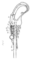
- a lawn and garden tool and, more specifically, a string trimmer 10 includes an upper housing 12, a lower housing 14 having a cutting mechanism 15 disposed therein and a shaft 16 that connects the upper housing 12 to the lower housing 14.
- the string trimmer 10 may be powered electrically, by a gas driven motor or in any other manner and may operate to rotate the cutting mechanism 15 within the lower housing 14 in any known or desired manner.
- the upper housing 12 includes a trigger 17 disposed in a main handle 18. When actuated, the trigger 17 causes power to be delivered to the cutting mechanism 15 to effect rotation of the cutting mechanism.
- the upper housing 12 also includes a push-button mechanism 19 located in an easily accessible place on, for example, the top of the upper housing 12 between the main handle 18 and an auxiliary handle 20 to allow telescoping and/or rotation of the shaft 16 with respect to the upper housing 12.
- the push-button mechanism 19 may be actuated by an operator using a single finger (e.g., a thumb) to push the button 19 toward the lower housing 14.
- the push-button mechanism 19 is easy to actuate and does not require the operator to bend over and grasp the lower housing 14 of the string trimmer 10.
- the push-button mechanism 19 may be moved in a simple and convenient manner between a first position (illustrated in Fig. 1) in which the shaft 16 is locked in place with respect to the handle 18 and a second position in which the shaft 16 may be elongated, shortened and/or rotated with respect to the handle 18 to thereby enable axial movement and/or rotation of the lower housing 14 with respect to the handle 18.
- Rotation of the lower housing 14 with respect to the handle 18 by 180 degrees converts the string trimmer 10 from a device that cuts in a horizontal plane to a device that cuts in a vertical plane, or vice-versa.
- the push-button mechanism 19, which comprises a locking member is biased toward the first position so that, when the push-button mechanism 19 is released, it returns to the first position thereby locking the shaft 16 in place with respect to the handle 18.
- the push-button mechanism 19 is biased toward a rear end of the upper housing 12 by a spring 21 disposed between a spring seat 22 mounted on an interior wall of the housing 12 and a rear wall 23 of the push-button mechanism 19.
- the push-button mechanism 19 includes a slanted locking surface 24 that, when in the locking position illustrated in Figs. 2 and 3, is disposed in contact with a complementary slanting locking surface 25 of a detent locking mechanism 26 to hold the detent locking mechanism 26 in place.
- the detent locking mechanism 26 has a detent 27 adapted to fit within each of a plurality of axially spaced indentations 28a-28d and 29a-29d extending into the wall of the shaft 16.
- the indentations 28a-28d are preferably axially aligned with one another at a first circumferential location and the indentations 29a-29d are preferably aligned with one another at a second circumferential location. Also preferably, the second circumferential location is diametrically opposite the first circumferential location.
- the indentations 28 and 29 are preferably shaped to conform to the detent 27 so as to produce minimal friction when the detent 27 slides into and out of the indentations 28 and 29.
- the indentations 28 and 29 could comprise holes through the wall of the shaft 16 or other types of depressions within the shaft 16.
- the shaft 16 is held in place when the locking surface 24 of the push-button mechanism 19 is disposed in contact with the locking surface 25 of the detent locking mechanism 26.
- the shaft 16 rides within a guide 30 having a circular aperture formed by ribs 32 (only some of which are marked in Fig. 3) formed on interior walls of the housing 12. While only the interior of a first half of the housing 12 is illustrated in Figs. 2 and 3, the second half of the housing 12 includes ribs formed in a pattern that is essentially a mirror image of the rib pattern illustrated in Fig. 3 so that, when the two halves of the housing 12 are connected together, the ribs 32 form the guide 30 as a circular aperture adapted to accept the shaft 16.
- the locking surface 24 slides away from the complementary locking surface 25 of the detent locking mechanism 26 which, in turn, allows the detent 27 to move upward and out of the indentation 28 (or 29) of the shaft 16 upon axial or rotational movement of the shaft 16.
- the detent locking mechanism 26 is biased toward the shaft 16 by a torsional spring 34 which provides the operator with tactile feedback indicating when the detent 27 slides into or out of one of the indentations 28 or 29 of the shaft 16 during movement of the shaft 16.
- the shaft 16 when the push-button mechanism 19 is pushed forward into the second position, the shaft 16 may be moved axially within the guide 30 to lengthen or shorten the distance between the upper housing 12 and the lower housing 14 and/or the shaft 16 may be rotated to change the orientation of the lower housing 14 with respect to the upper housing 12.
- the push-button mechanism 19 may be released, at which time the spring 21 forces the locking surface 24 back into contact with the locking surface 25 to thereby lock the detent 27 against the shaft 16 which, in turn, holds the shaft 16 in place.
- the detent locking mechanism 26 may be locked only when the detent 27 is within one of the indentations 28 or 29 of the shaft 16 to assure that the shaft 16 is securely held in place.
- the detent locking mechanism 26 may be designed so that it can be locked into place when the detent 27 is located at some point between any two of the indentations 28 and/or 29.
- the guide 30 includes an axial channel 40 that extends along a portion of the length of each half of the upper housing 12 and one or more circumferential channels 42 that extend 180 degrees around the circumference of the shaft 16 when the shaft 16 is inserted into the guide 30.
- the circumferential channels 42 are interconnected with the axial channels 40 and, preferably, are regularly spaced along the length of the axial channels 40.
- the shaft 16 includes a single boss 46 (or other pin-type element) disposed on an exterior surface of the shaft 16 at a point midway between the first series of axially spaced indentations 28 and the second series of axially spaced indentations 29.
- boss 46 or other pin-type element
- the shaft 16 is disposed within the guide 30 so that the boss 46 resides within one of the axial channels 40 and is constrained from axial movement at either end of the axial channels 40 by end walls 50 and 52.
- the boss 46 may freely move between the axial channels 40 (one on each half of the upper housing 12) and any one of the circumferential channels 42 so that the shaft 16 may be moved axially when the boss 46 is within one of the axial channels 40 and may be rotated when the boss 46 is within one of the circumferential channels 42.
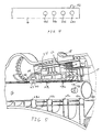
- the indentations 28 and 29 of the shaft 16 are preferably aligned so that, when the boss 46 is disposed at an intersection of one of the circumferential channels 42 and one of the axial channels 40, as illustrated in Figs. 2 and 5, the detent 27 of the detent locking mechanism 26 is disposed within one of the indentations 28 or 29.
- the detent 27 resides in the indentation 28d farthest away from the boss 46.
- the string trimmer 10 may be configured for normal trimming operation.
- the boss 46 resides in the axial channel 40 on the opposite half of the upper housing 12 (i.e., the portion not shown in Fig. 5).
- the string trimmer 10 may be configured for edging operation.
- the shaft 16 may be extended from the position illustrated in Fig. 5 by moving the boss 46 of the shaft 16 toward the front of the upper housing 12 causing the detent 27 to slide into and out of consecutive ones of the indentations 29.
- the shaft 16 may also be rotated so that the boss 46 rides in any of the other circumferential channels 42.
- the shaft 16 may be moved axially and may be rotated with respect to the upper housing 12 in any manner defined by movement of the boss 46 within the interconnected channels 40 and 42. During this time, the predetermined axial and rotational positions at which the shaft 16 can be locked into place are indicated by the tactile feedback provided by the spring-biased detent locking mechanism 26 riding against the shaft 16. As will also be understood, the shaft 16 may be locked into place at any of the positions where one of the indentations 28 or 29 on the shaft 16 is contacted by the detent 27.
- the string trimmer 10 has been described herein as including four circumferential channels 42 and four axially spaced indentations on two opposing circumferential locations of the shaft 16, the string trimmer 10 could include any other number of circumferential channels and/or any other number of axially spaced indentations at one or more (e.g., two, three, four, etc.) circumferential locations of the shaft 16, to thereby allow movement and rotation of the shaft 16 to other predetermined axial or rotational positions. Furthermore, if desired, the shaft 16 can be locked into place at positions other than those at which indentations 28 and 29 are provided and, thus, the shaft 16 may be elongated or shortened to lengths other than those associated with the indentations 28 and 29.
- the present invention has been described herein as including a boss 46 on the shaft 16 and channels 40 and 42 formed within the upper housing 12, the boss 46 could alternatively be located on the upper housing 12 and positioned so that it rides in circumferential and axial channels formed in the shaft 16.
- the shaft telescoping and rotational adjustment mechanism of the present invention has been described herein for use on a string trimmer, this mechanism can also be used on other lawn and garden tools, such as blowers, brush cutters, etc.
Landscapes
- Life Sciences & Earth Sciences (AREA)
- Environmental Sciences (AREA)
- Engineering & Computer Science (AREA)
- Mechanical Engineering (AREA)
- Harvester Elements (AREA)
Abstract
Description
Claims (20)
- A lawn and garden tool comprising:a lower housing;an upper housing having a handle, a trigger and an axial channel interconnected with a circumferential channel; anda shaft connected between the upper housing and the lower housing having a boss adapted to travel in the interconnected axial channel and circumferential channel, wherein movement of the boss within the axial channel telescopes the shaft and movement of the boss within the circumferential channel rotates the lower housing with respect to the upper housing.
- The tool of claim 1, further including a locking mechanism disposed on the upper housing to lock the shaft at a particular position.
- The tool of claim 2, wherein the locking mechanism includes a detent mechanism adjacent a locking member that is moveable between first and second positions, wherein the locking member comes into contact with and prevents movement of the detent mechanism when the locking member is in the first position and wherein the locking member allows movement of the detent mechanism when the locking member is in the second position.
- The tool of claim 3, wherein the locking member includes a spring that biases the locking member toward the first position.
- The tool of claim 3, wherein the locking member includes an operator actuated member that causes movement of the locking member between the first and second positions when actuated by an operator.
- The tool of claim 3, wherein the handle comprises a main handle and further including an auxiliary handle, wherein the locking mechanism is disposed on the upper housing between the main handle and the auxiliary handle.
- The tool of claim 1, wherein the circumferential channel comprises a first circumferential channel interconnected with the axial channel at a first axial position and further including additional circumferential channels interconnected with the axial channel at additional axial positions.
- The tool of claim 7, further including an additional axial channel interconnected with the first circumferential channel and the additional circumferential channels.
- The tool of claim 1, further including a detent mechanism having a detent that locks the shaft in place and wherein the shaft includes indentations therein capable of accepting the detent.
- The tool of claim 9, wherein the indentations are spaced so that the detent resides within one of the indentations when the boss is located at an intersection of the axial channel and the circumferential channel.
- A lawn and garden tool comprising:a shaft; anda housing having a guide adapted to accept the shaft therein;wherein one of the shaft and the guide includes a plurality of axial channels interconnected with a plurality of circumferential channels and wherein the other one of the shaft and the guide includes a boss movably disposed within the channels to move between the axial channels and the circumferential channels and wherein movement of the boss within the axial channels telescopes the shaft with respect to the housing and movement of the boss within the circumferential channels rotates the shaft with respect to the housing.
- The tool of claim 11, wherein the housing further includes a locking mechanism having an operator actuated locking member moveable between first and second positions and a locking device coupled to the locking member and disposed adjacent the shaft, wherein movement of the operator actuated locking member into the first position forces the locking device to hold the shaft at a stable position with respect to the housing and wherein movement of the operator actuated locking member into the second position allows movement of the locking device with respect to the shaft.
- The tool of claim 12, wherein the shaft includes a plurality of indentations and wherein the locking device includes a detent mechanism having a detent that comes into contact with the shaft and is adapted to fit within the indentations.
- The tool of claim 13, wherein a first one of the plurality of indentations is angularly offset from a second one of the plurality indentations by approximately 180 degrees.
- The tool of claim 13, wherein the indentations are spaced so that the detent resides within one of the indentations when the boss is located at an intersection of one of the axial channels and one of the circumferential channels.
- A lawn and garden tool comprising:a lower housing;an upper housing including a guide, an operator actuated push-button mechanism including a first slanting surface that is biased in a first position and that is moveable to a second position, and a locking device having a cooperating slanting surface disposed adjacent the first slanting surface when the operator actuated push-button mechanism is in the first position; anda shaft disposed within the guide and extending from the upper housing to the lower housing;wherein the shaft is locked at a fixed location with respect to the upper housing by the locking device when the operator actuated push-button mechanism is in the first position and wherein the shaft is adapted to move axially with respect to the upper housing and to rotate with respect to the upper housing when the operator actuated push-button mechanism is in the second position.
- The tool of claim 16, wherein one of the shaft and the guide includes an axial channel interconnected with a circumferential channel and wherein the other one of the shaft and the guide includes a boss movably disposed within the channels to move back and forth between the axial channel and the circumferential channel such that movement of the boss within the axial channel telescopes the shaft with respect to the upper housing and movement of the boss within the circumferential channel rotates the shaft with respect to the upper housing.
- The tool of claim 17, wherein the one of the shaft and the guide includes a plurality of circumferential channels interconnected with a plurality of axial channels.
- The tool of claim 18, wherein the locking device includes a detent and the shaft includes a multiplicity of indentations that are adapted to accept the detent and that are spaced so that the detent resides within one of the indentations when the boss is located at an intersection of one of the axial channels and one of the circumferential channels.
- The tool of claim 16, wherein the operator actuated push-button mechanism includes a first spring that biases the operator actuated push-button mechanism in the first position and wherein the locking device includes a second spring that biases the locking device toward the shaft.
Applications Claiming Priority (2)
| Application Number | Priority Date | Filing Date | Title |
|---|---|---|---|
| US08/898,990 US5933966A (en) | 1997-07-23 | 1997-07-23 | Shaft telescoping and rotational adjustment mechanism for a lawn and garden tool |
| US898990 | 1997-07-23 |
Publications (2)
| Publication Number | Publication Date |
|---|---|
| EP0893045A1 true EP0893045A1 (en) | 1999-01-27 |
| EP0893045B1 EP0893045B1 (en) | 2003-04-09 |
Family
ID=25410352
Family Applications (1)
| Application Number | Title | Priority Date | Filing Date |
|---|---|---|---|
| EP98400153A Expired - Lifetime EP0893045B1 (en) | 1997-07-23 | 1998-01-26 | Shaft telescoping and rotational adjustment mechanism for a lawn and garden tool |
Country Status (4)
| Country | Link |
|---|---|
| US (1) | US5933966A (en) |
| EP (1) | EP0893045B1 (en) |
| CA (1) | CA2227656A1 (en) |
| DE (1) | DE69813101D1 (en) |
Cited By (4)
| Publication number | Priority date | Publication date | Assignee | Title |
|---|---|---|---|---|
| EP1623615A1 (en) * | 2004-08-04 | 2006-02-08 | Robert Bosch Gmbh | Garden tool adjustment |
| EP2216143A3 (en) * | 2009-02-05 | 2012-01-18 | GARDENA Manufacturing GmbH | Handheld device with a telescopic handle and device system with such a device |
| CN104303690A (en) * | 2014-10-16 | 2015-01-28 | 苏州金莱克精密机械有限公司 | One-key telescopic mechanism of grass trimmer |
| EP3275599A1 (en) | 2016-07-25 | 2018-01-31 | Andreas Stihl AG & Co. KG | Assembly comprising a housing and guide tube, hand-held working machine comprising a housing and guide tube |
Families Citing this family (30)
| Publication number | Priority date | Publication date | Assignee | Title |
|---|---|---|---|---|
| DE19956332A1 (en) * | 1999-11-23 | 2001-05-31 | Stihl Maschf Andreas | Free cutter driven by internal combustion engine, with engine casing collar co-axially overlapping engine-side end of guide tube |
| US6439088B1 (en) | 2000-04-25 | 2002-08-27 | The Toro Company | Reconfigurable vegetation trimmer and method of use |
| US6769494B2 (en) * | 2001-04-30 | 2004-08-03 | Powerqwest, Inc. | Combination line trimmer and edger |
| SE520705C2 (en) * | 2001-12-17 | 2003-08-12 | Electrolux Ab | hanging loop |
| US8186066B2 (en) * | 2002-11-19 | 2012-05-29 | Husqvarna Ab | Motor driven tool such as a pole hedge trimmer with a locking mechanism for the turnable cutting unit |
| SE524198C2 (en) * | 2002-11-19 | 2004-07-06 | Electrolux Ab | Motor-driven work tools eg. bar hedge shears with a locking mechanism for the angle adjustment between a cutting unit and a bar |
| US7134208B2 (en) | 2002-12-23 | 2006-11-14 | Black & Decker Inc. | Ergonomic handle for vegetation trimmer |
| US20050193699A1 (en) * | 2004-02-13 | 2005-09-08 | Hatfield Charles C. | String trimmer-lawn mower multi-task unit |
| US7219488B2 (en) * | 2004-02-13 | 2007-05-22 | Charles Hatfield | Mounting apparatus for string trimmer for and with lawn mower multi-task unit |
| US7314096B2 (en) * | 2004-10-27 | 2008-01-01 | The Toro Company | Adjustable handle for portable tool |
| US7257909B2 (en) * | 2004-10-27 | 2007-08-21 | The Toro Company | Convertible yard tool |
| USD524824S1 (en) | 2004-10-27 | 2006-07-11 | The Toro Company | Convertible yard tool |
| USD519127S1 (en) | 2004-10-27 | 2006-04-18 | The Toro Company | Housing for convertible yard tool |
| USD566491S1 (en) | 2006-12-26 | 2008-04-15 | The Toro Company | Vegetation trimmer |
| DE202008011648U1 (en) * | 2008-09-02 | 2010-03-11 | Dolmar Gmbh | coupling member |
| US8382059B2 (en) * | 2008-09-09 | 2013-02-26 | Zero Chroma, LLC | Holder for electronic device with support |
| US8720071B2 (en) * | 2010-03-05 | 2014-05-13 | Wayne Galinski | Weed trimmer with accuracy shield |
| US8667648B2 (en) * | 2011-08-26 | 2014-03-11 | Mtd Products Inc | Ball handle assembly for a handheld tool |
| DE102012007405B4 (en) * | 2012-04-16 | 2017-02-09 | Andreas Stihl Ag & Co. Kg | implement |
| US9346077B2 (en) | 2013-03-15 | 2016-05-24 | The Sherwin-Williams Company | Quick fit adjustment mechanism for extension pole system for paint roller |
| US9127699B2 (en) * | 2013-03-15 | 2015-09-08 | The Sherwin-Williams Company | Quick fit adjustment mechanism for extension pole system for paint roller |
| JP5995785B2 (en) * | 2013-05-31 | 2016-09-21 | 株式会社マキタ | Brush cutter |
| US10314228B2 (en) * | 2014-05-16 | 2019-06-11 | Positec Power Tools (Suzhou) Co., Ltd. | Grass trimmer and cord delivering method of grass trimmer |
| DE102016106557A1 (en) * | 2016-04-11 | 2017-10-12 | Festool Gmbh | Hand machine tool with a drive motor |
| US11051450B2 (en) * | 2018-11-09 | 2021-07-06 | The Toro Company | Walk reel mower with a telescopic handle assembly |
| DE102018219390A1 (en) * | 2018-11-14 | 2020-05-14 | Robert Bosch Gmbh | Actuating unit, locking unit and clamping unit for a hand machine tool |
| US11518018B2 (en) | 2019-01-21 | 2022-12-06 | Milwaukee Electric Tool Corporation | Power tool with non-conductive driveshaft |
| US11384719B2 (en) | 2019-03-15 | 2022-07-12 | Milwaukee Electric Tool Corporation | Fluid tank for a power tool |
| US11618149B2 (en) | 2019-04-26 | 2023-04-04 | Milwaukee Electric Tool Corporation | Telescoping tool with collapsible bearing assembly |
| EP4653164A1 (en) * | 2023-04-21 | 2025-11-26 | Nanjing Chervon Industry Co., Ltd. | Chain saw |
Citations (6)
| Publication number | Priority date | Publication date | Assignee | Title |
|---|---|---|---|---|
| DE3046286A1 (en) * | 1980-12-09 | 1982-07-08 | Vorwerk & Co Interholding Gmbh, 5600 Wuppertal | LATCHING FOR TELESCOPICOUS GUIDES |
| US5288161A (en) * | 1992-02-14 | 1994-02-22 | The Wooster Brush Company | Quick release lock mechanisms |
| EP0653364A2 (en) | 1993-11-09 | 1995-05-17 | Black & Decker Inc. | Improved shaft assembly |
| EP0703044A1 (en) * | 1994-09-02 | 1996-03-27 | Goblin Limited | Adjustable connection |
| WO1996025843A1 (en) * | 1995-02-21 | 1996-08-29 | Wci Outdoor Products, Inc. | Lawn trimming and edging apparatus with pivotable motor head |
| DE19632400A1 (en) * | 1996-03-11 | 1997-09-18 | Vorwerk Co Interholding | Parts that can be telescoped into one another |
Family Cites Families (20)
| Publication number | Priority date | Publication date | Assignee | Title |
|---|---|---|---|---|
| US2091495A (en) * | 1935-07-30 | 1937-08-31 | Steen John | Extensible handle for caskets |
| US3317997A (en) * | 1965-10-11 | 1967-05-09 | Wiss And Sons Co J | Telescoping adjustable long handle multipurpose shears |
| US4052789A (en) * | 1976-12-02 | 1977-10-11 | Weed Eater, Inc. | Rotary cutting assembly |
| US4156967A (en) * | 1976-12-02 | 1979-06-05 | Weed Eater, Inc. | Rotary cutting assembly |
| DE8012962U1 (en) * | 1980-05-13 | 1980-08-14 | Max Langenstein, Feld- Und Gartengeraete Gmbh & Co, 7918 Illertissen | LAWN EDGE CUTTER |
| US4409866A (en) * | 1981-12-28 | 1983-10-18 | Mcbride Joan | Tool handle with contoured through passageway and spring biased trigger |
| US4463498A (en) * | 1982-08-31 | 1984-08-07 | Everts Robert G | Coupling for flailing line trimmer handles |
| US4733471A (en) * | 1984-05-08 | 1988-03-29 | Hawaiian Motor Co. | Tool drive assembly and clamp |
| US4603478A (en) * | 1984-08-13 | 1986-08-05 | Allegretti & Company | Trimmer with adjustable handle |
| US4825548A (en) * | 1987-03-31 | 1989-05-02 | White Consolidated Industries, Inc. | Vibration-damping control handle for a portable power tool |
| GB8714817D0 (en) * | 1987-06-24 | 1987-07-29 | Flymo Ltd | Grass trimmer |
| US4829675A (en) * | 1987-08-19 | 1989-05-16 | The Toro Company | Electrical appliance and handle for same |
| AU614548B2 (en) * | 1988-10-26 | 1991-09-05 | Tanaka Kogyo Co., Ltd. | Hand-held machine |
| DE3837190C1 (en) * | 1988-11-02 | 1990-02-22 | Lemfoerder Metallwaren Ag, 2844 Lemfoerde, De | |
| USRE34358E (en) * | 1989-06-01 | 1993-08-31 | Telescopic hedge trimming apparatus | |
| US4936886A (en) * | 1989-07-12 | 1990-06-26 | Snapper Power Equipment Division Of Fuqua Indistries, Inc. | Wheel mounted string trimmer |
| DE4117340A1 (en) * | 1991-05-27 | 1992-12-03 | Wolf Geraete Gmbh | THREAD CUTTER |
| US5446964A (en) * | 1993-07-22 | 1995-09-05 | Wci Outdoor Products, Inc. | Apparatus and method for packaging and assembling a flexible line trimmer |
| GB9325353D0 (en) * | 1993-12-10 | 1994-02-16 | Black & Decker Inc | Improved electrically powered tool |
| US5628088A (en) * | 1995-07-24 | 1997-05-13 | Chen; Chang-Wen | Multistage adjustable device for trunk bracket |
-
1997
- 1997-07-23 US US08/898,990 patent/US5933966A/en not_active Expired - Fee Related
-
1998
- 1998-01-21 CA CA002227656A patent/CA2227656A1/en not_active Abandoned
- 1998-01-26 DE DE69813101T patent/DE69813101D1/en not_active Expired - Lifetime
- 1998-01-26 EP EP98400153A patent/EP0893045B1/en not_active Expired - Lifetime
Patent Citations (7)
| Publication number | Priority date | Publication date | Assignee | Title |
|---|---|---|---|---|
| DE3046286A1 (en) * | 1980-12-09 | 1982-07-08 | Vorwerk & Co Interholding Gmbh, 5600 Wuppertal | LATCHING FOR TELESCOPICOUS GUIDES |
| US5288161A (en) * | 1992-02-14 | 1994-02-22 | The Wooster Brush Company | Quick release lock mechanisms |
| US5594990A (en) | 1993-07-22 | 1997-01-21 | Wci Outdoor Products, Inc. | Lawn trimming and edging apparatus having motor housing rotatable on extendable handle |
| EP0653364A2 (en) | 1993-11-09 | 1995-05-17 | Black & Decker Inc. | Improved shaft assembly |
| EP0703044A1 (en) * | 1994-09-02 | 1996-03-27 | Goblin Limited | Adjustable connection |
| WO1996025843A1 (en) * | 1995-02-21 | 1996-08-29 | Wci Outdoor Products, Inc. | Lawn trimming and edging apparatus with pivotable motor head |
| DE19632400A1 (en) * | 1996-03-11 | 1997-09-18 | Vorwerk Co Interholding | Parts that can be telescoped into one another |
Cited By (4)
| Publication number | Priority date | Publication date | Assignee | Title |
|---|---|---|---|---|
| EP1623615A1 (en) * | 2004-08-04 | 2006-02-08 | Robert Bosch Gmbh | Garden tool adjustment |
| EP2216143A3 (en) * | 2009-02-05 | 2012-01-18 | GARDENA Manufacturing GmbH | Handheld device with a telescopic handle and device system with such a device |
| CN104303690A (en) * | 2014-10-16 | 2015-01-28 | 苏州金莱克精密机械有限公司 | One-key telescopic mechanism of grass trimmer |
| EP3275599A1 (en) | 2016-07-25 | 2018-01-31 | Andreas Stihl AG & Co. KG | Assembly comprising a housing and guide tube, hand-held working machine comprising a housing and guide tube |
Also Published As
| Publication number | Publication date |
|---|---|
| DE69813101D1 (en) | 2003-05-15 |
| EP0893045B1 (en) | 2003-04-09 |
| CA2227656A1 (en) | 1999-01-23 |
| US5933966A (en) | 1999-08-10 |
Similar Documents
| Publication | Publication Date | Title |
|---|---|---|
| US5933966A (en) | Shaft telescoping and rotational adjustment mechanism for a lawn and garden tool | |
| EP0893206B1 (en) | Apparatus for adjusting relative positions of first and second members, particularly referring to the relative position between a main handle and an auxiliary handle on a portable tool | |
| EP0653364B1 (en) | Improved shaft assembly | |
| EP1057594B1 (en) | Manual emergency tool assembly | |
| US6364033B1 (en) | Portable electric tool | |
| AU749340B2 (en) | A power tool having interchangeable tool head | |
| US6006434A (en) | Quick-release component connector for lawn tool | |
| EP0940832B1 (en) | Multimate project-a switch lock-off mechanism | |
| EP0899065B1 (en) | A power tool having an interchangeable tool head | |
| US8793886B2 (en) | Power tool with a rotatable working head | |
| EP3777508B1 (en) | String trimmer with blower | |
| US10874046B2 (en) | Quick loading trimmer head and trimmer thereto | |
| US4283855A (en) | Sabre saw with rotatable saw bar | |
| AU2004201628B2 (en) | Ergonomic handle for vegetation trimmer | |
| US4236311A (en) | Vegetation cutting apparatus | |
| US20160227705A1 (en) | String trimmer head | |
| KR101067518B1 (en) | Mowers | |
| US20090235536A1 (en) | Multipurpose hedge trimmer deflector | |
| US6821048B2 (en) | Coupling apparatus for a rotary hand tool | |
| CA2521970A1 (en) | Shaft telescoping and rotational adjustment mechanism for a lawn and garden tool | |
| EP0703044A1 (en) | Adjustable connection | |
| CA2613736A1 (en) | Combination string trimmer and blower tool | |
| JP5376247B2 (en) | Impact tool |
Legal Events
| Date | Code | Title | Description |
|---|---|---|---|
| PUAI | Public reference made under article 153(3) epc to a published international application that has entered the european phase |
Free format text: ORIGINAL CODE: 0009012 |
|
| AK | Designated contracting states |
Kind code of ref document: A1 Designated state(s): DE FR GB IT |
|
| AX | Request for extension of the european patent |
Free format text: AL;LT;LV;MK;RO;SI |
|
| AKX | Designation fees paid | ||
| RBV | Designated contracting states (corrected) |
Designated state(s): DE FR GB IT |
|
| 17P | Request for examination filed |
Effective date: 19990920 |
|
| 17Q | First examination report despatched |
Effective date: 20010313 |
|
| GRAG | Despatch of communication of intention to grant |
Free format text: ORIGINAL CODE: EPIDOS AGRA |
|
| GRAG | Despatch of communication of intention to grant |
Free format text: ORIGINAL CODE: EPIDOS AGRA |
|
| GRAH | Despatch of communication of intention to grant a patent |
Free format text: ORIGINAL CODE: EPIDOS IGRA |
|
| GRAH | Despatch of communication of intention to grant a patent |
Free format text: ORIGINAL CODE: EPIDOS IGRA |
|
| RAP1 | Party data changed (applicant data changed or rights of an application transferred) |
Owner name: AB ELECTROLUX |
|
| GRAA | (expected) grant |
Free format text: ORIGINAL CODE: 0009210 |
|
| AK | Designated contracting states |
Designated state(s): DE FR GB IT |
|
| PG25 | Lapsed in a contracting state [announced via postgrant information from national office to epo] |
Ref country code: IT Free format text: LAPSE BECAUSE OF FAILURE TO SUBMIT A TRANSLATION OF THE DESCRIPTION OR TO PAY THE FEE WITHIN THE PRE;WARNING: LAPSES OF ITALIAN PATENTS WITH EFFECTIVE DATE BEFORE 2007 MAY HAVE OCCURRED AT ANY TIME BEFORE 2007. THE CORRECT EFFECTIVE DATE MAY BE DIFFERENT FROM THE ONE RECORDED.SCRIBED TIME-LIMIT Effective date: 20030409 |
|
| REG | Reference to a national code |
Ref country code: GB Ref legal event code: FG4D |
|
| PG25 | Lapsed in a contracting state [announced via postgrant information from national office to epo] |
Ref country code: DE Free format text: LAPSE BECAUSE OF FAILURE TO SUBMIT A TRANSLATION OF THE DESCRIPTION OR TO PAY THE FEE WITHIN THE PRESCRIBED TIME-LIMIT Effective date: 20030710 |
|
| PGFP | Annual fee paid to national office [announced via postgrant information from national office to epo] |
Ref country code: FR Payment date: 20030711 Year of fee payment: 6 |
|
| ET | Fr: translation filed | ||
| PG25 | Lapsed in a contracting state [announced via postgrant information from national office to epo] |
Ref country code: GB Free format text: LAPSE BECAUSE OF NON-PAYMENT OF DUE FEES Effective date: 20040126 |
|
| PLBE | No opposition filed within time limit |
Free format text: ORIGINAL CODE: 0009261 |
|
| STAA | Information on the status of an ep patent application or granted ep patent |
Free format text: STATUS: NO OPPOSITION FILED WITHIN TIME LIMIT |
|
| 26N | No opposition filed |
Effective date: 20040112 |
|
| GBPC | Gb: european patent ceased through non-payment of renewal fee |
Effective date: 20040126 |
|
| PG25 | Lapsed in a contracting state [announced via postgrant information from national office to epo] |
Ref country code: FR Free format text: LAPSE BECAUSE OF NON-PAYMENT OF DUE FEES Effective date: 20050930 |
|
| REG | Reference to a national code |
Ref country code: FR Ref legal event code: ST |
|
| PG25 | Lapsed in a contracting state [announced via postgrant information from national office to epo] |
Ref country code: FR Free format text: LAPSE BECAUSE OF NON-PAYMENT OF DUE FEES Effective date: 20040131 |