EP0893846A1 - Appareil électrique portant un support de contact fixe et une borne de raccordement - Google Patents
Appareil électrique portant un support de contact fixe et une borne de raccordement Download PDFInfo
- Publication number
- EP0893846A1 EP0893846A1 EP98401725A EP98401725A EP0893846A1 EP 0893846 A1 EP0893846 A1 EP 0893846A1 EP 98401725 A EP98401725 A EP 98401725A EP 98401725 A EP98401725 A EP 98401725A EP 0893846 A1 EP0893846 A1 EP 0893846A1
- Authority
- EP
- European Patent Office
- Prior art keywords
- connection
- cage
- fixed contact
- cable
- terminal
- Prior art date
- Legal status (The legal status is an assumption and is not a legal conclusion. Google has not performed a legal analysis and makes no representation as to the accuracy of the status listed.)
- Granted
Links
- 238000003780 insertion Methods 0.000 claims description 7
- 230000037431 insertion Effects 0.000 claims description 7
- 230000001154 acute effect Effects 0.000 claims description 3
- 238000009434 installation Methods 0.000 description 2
- 238000004078 waterproofing Methods 0.000 description 2
- 241001080024 Telles Species 0.000 description 1
- 239000004020 conductor Substances 0.000 description 1
- 238000013016 damping Methods 0.000 description 1
- 238000009795 derivation Methods 0.000 description 1
- 238000006073 displacement reaction Methods 0.000 description 1
- 238000010616 electrical installation Methods 0.000 description 1
- 230000007257 malfunction Effects 0.000 description 1
- 239000002184 metal Substances 0.000 description 1
Images
Classifications
-
- H—ELECTRICITY
- H01—ELECTRIC ELEMENTS
- H01R—ELECTRICALLY-CONDUCTIVE CONNECTIONS; STRUCTURAL ASSOCIATIONS OF A PLURALITY OF MUTUALLY-INSULATED ELECTRICAL CONNECTING ELEMENTS; COUPLING DEVICES; CURRENT COLLECTORS
- H01R4/00—Electrically-conductive connections between two or more conductive members in direct contact, i.e. touching one another; Means for effecting or maintaining such contact; Electrically-conductive connections having two or more spaced connecting locations for conductors and using contact members penetrating insulation
- H01R4/28—Clamped connections, spring connections
- H01R4/30—Clamped connections, spring connections utilising a screw or nut clamping member
- H01R4/305—Clamped connections, spring connections utilising a screw or nut clamping member having means for facilitating engagement of conductive member or for holding it in position
-
- H—ELECTRICITY
- H01—ELECTRIC ELEMENTS
- H01R—ELECTRICALLY-CONDUCTIVE CONNECTIONS; STRUCTURAL ASSOCIATIONS OF A PLURALITY OF MUTUALLY-INSULATED ELECTRICAL CONNECTING ELEMENTS; COUPLING DEVICES; CURRENT COLLECTORS
- H01R4/00—Electrically-conductive connections between two or more conductive members in direct contact, i.e. touching one another; Means for effecting or maintaining such contact; Electrically-conductive connections having two or more spaced connecting locations for conductors and using contact members penetrating insulation
- H01R4/28—Clamped connections, spring connections
- H01R4/30—Clamped connections, spring connections utilising a screw or nut clamping member
- H01R4/36—Conductive members located under tip of screw
- H01R4/363—Conductive members located under tip of screw with intermediate part between tip and conductive member
Definitions
- the present invention relates generally to an apparatus electric carrying a connection terminal intended to be tightened around a fixed contact support of said device to perform the connection between external electrical conductors and the device electric.
- Electrical devices for example electrical contactors, have a fixed contact support protruding outwards from their housing and electrically connected to the circuit they contain, this support is intended to ensure the connection of external electrical cables with the internal circuit of the device.
- a connection terminal implemented with the device ensures the electrical connection of at least one cable to the fixed contact support.
- connection terminals usually used allow making one or two electrical connections.
- Such bollards include a cage intended to be placed around fixed contact support and a clamping screw passing through a wall of said cage to cause it to move axially in a direction parallel to said clamping screw.
- the lower portion of the cage is brought closer to the lower end of the clamping screw so as to pinch the fixed contact support between the cage and the clamping screw.
- Space between the fixed contact support and the cage creates a zone of connection into which the stripped end can be inserted a cable.
- Some terminals also include an axially driven stirrup relative to the cage when tightening the tightening screw. Such terminals are arranged on the contactor so as to pinch the fixed contact support between the underside of the stirrup and the face bottom of the cage.
- Such clamp terminals can provide a single connection located in the connection area formed between the bracket and the support fixed contact.
- connection zones in which can be inserted electrical cables. It is thus possible to connect electrically one or two cables, arranged in one and / or the other connection area, to the circuit connected to the fixed contact support.
- connection terminals In these connection terminals, the clamping screw does not pass through the or the connection areas which makes it impossible to work of mechanical means usually used to make the "captive" connection, closed terminal (eyelet) or semi-closed terminal (fork) mounted on the end of the cable to be connected.
- Called captive connection a connection made up of in such a way that the cable cannot extract itself from the area connection when it comes to be loose.
- lockable connection a connection for which it is necessary to use a tool to extract the cable after removing both sides of the connection area.
- the object of the present invention is to provide an electrical device provided with a connection terminal allowing the realization of at minus a captive connection.
- the invention provides an electrical device, such as a contactor, carrying a fixed contact support protruding outside of its housing and a connection terminal of the type comprising a cage through which a clamping screw passes, said fixed contact support and said terminal comprising contact surfaces intended to establish an electrical contact with one or more external cables, characterized in what he wears a piece to create a zone of additional connection located between a contact surface and the part, said connection zone being constituted so as to hold the cable captive.
- a contactor carrying a fixed contact support protruding outside of its housing and a connection terminal of the type comprising a cage through which a clamping screw passes, said fixed contact support and said terminal comprising contact surfaces intended to establish an electrical contact with one or more external cables, characterized in what he wears a piece to create a zone of additional connection located between a contact surface and the part, said connection zone being constituted so as to hold the cable captive.
- the housing of the electrical appliance such as a contactor, is not shown, only the fixed contact support and the connection terminal are shown.
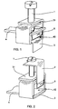
- connection terminal shown in Figure 1 is for the realization of a single connection, it consists of a screw clamping 1 and a cage 3.
- the cage 3 has four walls arranged perpendicularly to the together to form a rectangular opening ring. It is usually manufactured by folding a metal strip, the flat upper wall 31 consisting of two portions of overlapping strip.
- the clamping screw 1 is engaged with the internal thread of a tapped opening formed in the top wall of the cage so that said cage is driven axially in translation relative to the clamping screw during the rotation of said screw.
- this terminal is, as shown in drawing, arranged around the fixed contact support 4 in such a way that it is disposed between the lower end of the screw tightening 1 and the bottom wall of the cage 3.
- the screw is screwed clamping 1, while its lower end bears against the fixed contact support 4, the cage 3 is moved axially towards the high until it is against the underside of the support fixed contact 4.
- connection zone 43 The space arranged between the fixed contact support 4 and the wall bottom of the cage 3 constitutes a connection zone 43 in which can be inserted an electric cable.
- FIG. 2 shows a connection terminal according to another embodiment, which comprises, in addition to the clamping screw 1 and the cage 3, a bracket 2 mounted by its upper end on the head of the screw clamp 1. In such a terminal, the cage 3 is mounted so fixed.
- connection zone 42 is formed between the lower end of the bracket 2 and the fixed contact support.
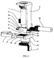
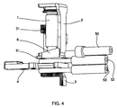
- connection terminals shown in Figures 3 to 5 are terminals with independent double connection, they are also consisting of a clamping screw 1, a U-shaped bracket 2 and a cage 3.
- the bracket 2 is mounted on the clamping screw 1 by positioning the upper end of it on the head of the clamping screw 1 and its lower end at near the lower end of said screw 1, inside the cage 3.
- the stirrup 2 can thus slide axially with respect to said clamping screw for the amount of mounting clearance.
- the terminal When the terminal is used to electrically connect one or more cable (s) to the electrical circuit of an electrical appliance (not shown in the drawing), for example an electrical contactor, terminated by a fixed contact support 4, it is positioned so that said fixed contact support 4 passes through the cage, and that the support of contact either inside the cage, between the lower end of the stirrup 2 and the lower end of the cage 3, being parallel to the ends opposite said stirrup and cage.
- an electrical appliance not shown in the drawing
- Bulges 41 arranged on either side of the contact zone 44 of the fixed contact support 4 are positioned against the edges external of the vertical sides 30 of the cage 3, only one of which is visible in the drawings.
- the double connection terminal is made integral with the fixed contact support 4, while being able slide vertically with respect to it, being guided by the side faces of the cage.
- connection zones 42 and 43 are arranged respectively between the fixed contact support 4 and the end bottom of the bracket 2 and between said fixed contact support 4 and the bottom wall of the cage 3. These two connection zones allow the positioning of cables intended to be connected electrically to the fixed contact support 4.
- the device comprising the fixed contact support 4 and a connection terminal is provided with a part 6, which can be called a waterproofing piece, mounted in one of the zones of connection of the terminal so as to create a additional and captive connection.
- said part 6 is positioned on the fixed contact support 4.
- said part 6 is positioned on the lower end of the bracket 2.
- said part 6 is arranged under a surface of contact.
- the part 6 consists of a flat face 60, rectangular in the example shown, connected to two faces side 61 finished, on their edge opposite the flat face 60, by returns 62 folded in the direction of one another.
- the lateral faces 61 are such that their edges are connected to the flat face 60 and returns 62 are not parallel to each other. By this arrangement, the flat face 60 forms an acute angle with the plane containing the returns 62. These lateral faces 61 are by trapezoidal example.
- This dihedral thus formed allows the user to easily insert the end of the cable, provided in a manner known per se with a ferrule 51, between part 6 and the stirrup 2.
- the tip 51 is a flat tip.
- the cable is inserted until the free end of the flat tip 51 protrudes the end of part 6 opposite the cable insertion side.
- the lateral faces 61 of the part 6 are, on the closed side of the dihedral, of just high enough to allow the end of the cable with cable end 51.
- the part 6 pivots while being pushed by the fixed contact support 4 during the approximation of the stirrup 2 and of the fixed contact support 4, while being held laterally at the during this movement through the side walls of the cage 3.
- the part 6 is, at the end of tightening, positioned with its flat face 60 parallel to the surfaces facing the stirrup and the fixed contact support. Said flat face 60 is then supported by its entire surface with the flat end 51 of the cable while the returns 62 extend to distance from the lower end of the stirrup 2, obliquely by compared to it.
- the establishment of the piece of impermeability 6 creates a zone additional captive connection while retaining the or the connection areas initially contained in the terminal.
- part 6 The assembly and use of part 6 are of course similar when the part 6 is mounted on the fixed contact support 4 as in Figure 1.
- said part is elastic and deforms during tightening of the terminal to secure the cable.
Landscapes
- Connections Arranged To Contact A Plurality Of Conductors (AREA)
- Multi-Conductor Connections (AREA)
- Coupling Device And Connection With Printed Circuit (AREA)
Abstract
Description
- câble raccordé à un circuit principal pour le contrôle de la présence de la tension électrique,
- dérivation d'un circuit principal pour l'auto-alimentation de la bobine d'un appareil,
- insertion momentanée, à la fermeture des pôles principaux, de résistances pour l'amortissement des pointes de courant pouvant apparaítre sur le circuit principal,
- livraison d'appareils précâblés avec bornes desserrées.
- la pièce est positionnée sous une des surfaces de contacts,
- la pièce est constituée d'une face plane reliée à deux faces latérales terminées, sur leur bord opposé à la face plane, par des retours repliés en direction l'un de l'autre,
- les bords des faces latérales se raccordant à la face plane et aux retours ne sont pas parallèles l'un à l'autre, de telle façon que la face plane forme un angle aigu avec le plan renfermant les retours,
- la pièce est accrochée à la surface de contact par la mise en place des retours sur le dessus de ladite surface de contact,
- les faces latérales sont trapézoïdales,
- la face plane de la pièce et la surface de contact forment entre elles un dièdre dont l'ouverture est dirigée du côté destiné à l'insertion du câble,
- les faces latérales sont, du côté fermé du dièdre, de hauteur juste suffisante pour permettre le passage de l'extrémité du câble, de sorte que l'extrémité du câble est maintenue pincée dans la zone de raccordement même lorsque la borne est desserrée,
- la pièce est susceptible d'être maintenue dans une position pour laquelle sa face plane est disposée contre la surface de contact par des moyens d'accrochage,
- lorsque la borne de raccordement comporte un étrier dont l'extrémité supérieure est montée sur la tête de la vis de serrage et l'extrémité inférieure est à proximité de l'extrémité inférieure de la vis, à l'intérieur de la cage, la pièce est montée à l'intérieur de la cage, sous la face inférieure de l'étrier,
- la pièce est positionnée sous le support de contact fixe.
- la figure 1 montre une borne de raccordement sans étrier à une zone de raccordement imperdable selon l'invention,
- la figure 2 montre une borne de raccordement à étrier destinée à assurer un seul raccordement électrique, équipée suivant l'invention,
- la figure 3 montre une borne à double raccordement indépendant selon l'invention avec un câble disposé dans la zone de raccordement imperdable,
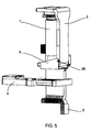
- la figure 4 montre la borne de la figure 1 assurant le raccordement de trois câbles,
- la figure 5 montre une variante de réalisation de la borne selon l'invention.
Claims (11)
- Appareil électrique, tel qu'un contacteur, portant un support de contact fixe (4) dépassant à l'extérieur de son boítier et une borne de raccordement du type comportant une cage (3) traversée par une vis de serrage (1), ledit support de contact fixe (4) et ladite borne comportant des surfaces de contact destinées à établir un contact électrique avec un ou des câbles externes, caractérisé en ce qu'il porte une pièce (6) permettant de créer une zone de raccordement supplémentaire située entre une surface de contact et la pièce (6), ladite zone de raccordement étant constituée de manière à maintenir le câble de manière imperdable.
- Appareil selon la revendication 1, caractérisé en ce que la pièce (6) est positionnée sous une des surfaces de contacts.
- Appareil selon la revendication 1 ou selon la revendication 2, caractérisé en ce que la pièce (6) est constituée d'une face plane (60) reliée à deux faces latérales (61) terminées, sur leur bord opposé à la face plane (60), par des retours (62) repliés en direction l'un de l'autre.
- Appareil selon la revendication 3, caractérisé en ce que les bords des faces latérales (61) se raccordant à la face plane (60) et aux retours (62) ne sont pas parallèles l'un à l'autre, de telle façon que la face plane (60) forme un angle aigu avec le plan renfermant les retours (62).
- Appareil selon la revendication 4, caractérisé en ce que la pièce (6) est accrochée à la surface de contact par la mise en place des retours (62) sur le dessus de ladite surface de contact.
- Appareil selon la revendication 4 ou selon la revendication 5, caractérisé en ce que les faces latérales (61) sont trapézoïdales.
- Appareil selon la revendication 6, caractérisé en ce que la face plane (60) de la pièce (6) et la surface de contact forment entre elles un dièdre dont l'ouverture est dirigée du côté destiné à l'insertion du câble.
- Appareil selon la revendication 7, caractérisé en ce que les faces latérales (61) sont, du côté fermé du dièdre, de hauteur juste suffisante pour permettre le passage de l'extrémité du câble, de sorte que l'extrémité du câble est maintenue pincée dans la zone de raccordement même lorsque la borne est desserrée.
- Appareil selon l'une quelconque des revendications précédentes, caractérisé en ce que la pièce est susceptible d'être maintenue dans une position pour laquelle sa face plane est disposée contre la surface de contact par des moyens d'accrochage.
- Appareil selon l'une quelconque des revendications précédentes dans lequel la borne de raccordement comporte un étrier (2) dont l'extrémité supérieure est montée sur la tête de la vis de serrage et l'extrémité inférieure est à proximité de l'extrémité inférieure de la vis, à l'intérieur de la cage, caractérisé en ce que la pièce (6) est montée à l'intérieur de la cage (3), sous la face inférieure de l'étrier.
- Appareil selon l'une quelconque des revendications précédentes, caractérisé en ce que la pièce (6) est positionnée sous le support de contact fixe (4).
Applications Claiming Priority (2)
| Application Number | Priority Date | Filing Date | Title |
|---|---|---|---|
| FR9709205 | 1997-07-21 | ||
| FR9709205A FR2766297B1 (fr) | 1997-07-21 | 1997-07-21 | Appareil electrique portant un support de contact fixe et une borne de raccordement |
Publications (2)
| Publication Number | Publication Date |
|---|---|
| EP0893846A1 true EP0893846A1 (fr) | 1999-01-27 |
| EP0893846B1 EP0893846B1 (fr) | 2002-09-11 |
Family
ID=9509409
Family Applications (1)
| Application Number | Title | Priority Date | Filing Date |
|---|---|---|---|
| EP19980401725 Expired - Lifetime EP0893846B1 (fr) | 1997-07-21 | 1998-07-08 | Appareil électrique portant un support de contact fixe et une borne de raccordement |
Country Status (4)
| Country | Link |
|---|---|
| EP (1) | EP0893846B1 (fr) |
| DE (1) | DE69807799T2 (fr) |
| ES (1) | ES2181139T3 (fr) |
| FR (1) | FR2766297B1 (fr) |
Cited By (5)
| Publication number | Priority date | Publication date | Assignee | Title |
|---|---|---|---|---|
| EP1028489A1 (fr) * | 1999-02-10 | 2000-08-16 | ABBPATENT GmbH | Dispositif de bornes de connexion pour des conducteurs à fil et des conducteurs plats de barre omnibus pour un appareillage électrique |
| EP2019449A2 (fr) | 2007-07-26 | 2009-01-28 | Abb Ag | Borne de connexion à vis et son procédé de fabrication |
| DE102010033112A1 (de) * | 2010-08-02 | 2012-02-02 | Siemens Aktiengesellschaft | Elektroinstallationsgerät |
| EP2429037A1 (fr) * | 2010-09-14 | 2012-03-14 | Siemens Aktiengesellschaft | Elément de serrage de cadre pour commutateurs électromécaniques doté d'une pièce de raccordement intégrée |
| LU502936B1 (de) * | 2022-10-20 | 2024-04-22 | Phoenix Contact Gmbh & Co | Schraubanschlussanordnung sowie Anschlussklemme |
Families Citing this family (5)
| Publication number | Priority date | Publication date | Assignee | Title |
|---|---|---|---|---|
| DE102006049810B4 (de) * | 2006-10-17 | 2008-07-10 | Siemens Ag | Leistungsschalter, insbesondere Kompaktleistungsschalter, und Hilfsleiteranschluss für einen Leistungsschalter |
| DE102011076563A1 (de) * | 2011-05-26 | 2012-11-29 | Siemens Aktiengesellschaft | Rahmenklemmelement für elektromechanische Schaltgeräte |
| FR2986664B1 (fr) * | 2012-02-03 | 2014-02-14 | Abb France | Borne de raccordement electrique |
| CN108767561B (zh) * | 2018-05-22 | 2019-12-06 | 上海航天科工电器研究院有限公司 | 一种锁线槽锁线的连接器 |
| DE202022103614U1 (de) * | 2022-06-29 | 2022-11-23 | Raycap Ip Development Ltd. | Modulare Überspannungsschutzgerätanordnungen und elektrische Anlagen, die diese beinhalten |
Citations (4)
| Publication number | Priority date | Publication date | Assignee | Title |
|---|---|---|---|---|
| FR1466954A (fr) * | 1965-02-04 | 1967-01-20 | Amp Inc | Connecteur électrique |
| DE29516450U1 (de) * | 1995-10-17 | 1995-12-07 | Electro-Terminal Gesellschaft m.b.H., Innsbruck | Elektrische Verbindungsklemme |
| DE9415318U1 (de) * | 1994-09-21 | 1996-01-25 | Jean Müller GmbH Elektrotechnische Fabrik, 65343 Eltville | Rahmenklemmhalterung zum Verbinden einer Anschlußfahne eines elektrischen Gerätes mit einem elektrischen Kabel |
| DE19513281A1 (de) * | 1995-04-07 | 1996-10-10 | Kopp Heinrich Ag | Kombianschlußklemme |
-
1997
- 1997-07-21 FR FR9709205A patent/FR2766297B1/fr not_active Expired - Fee Related
-
1998
- 1998-07-08 DE DE1998607799 patent/DE69807799T2/de not_active Expired - Fee Related
- 1998-07-08 EP EP19980401725 patent/EP0893846B1/fr not_active Expired - Lifetime
- 1998-07-08 ES ES98401725T patent/ES2181139T3/es not_active Expired - Lifetime
Patent Citations (4)
| Publication number | Priority date | Publication date | Assignee | Title |
|---|---|---|---|---|
| FR1466954A (fr) * | 1965-02-04 | 1967-01-20 | Amp Inc | Connecteur électrique |
| DE9415318U1 (de) * | 1994-09-21 | 1996-01-25 | Jean Müller GmbH Elektrotechnische Fabrik, 65343 Eltville | Rahmenklemmhalterung zum Verbinden einer Anschlußfahne eines elektrischen Gerätes mit einem elektrischen Kabel |
| DE19513281A1 (de) * | 1995-04-07 | 1996-10-10 | Kopp Heinrich Ag | Kombianschlußklemme |
| DE29516450U1 (de) * | 1995-10-17 | 1995-12-07 | Electro-Terminal Gesellschaft m.b.H., Innsbruck | Elektrische Verbindungsklemme |
Cited By (8)
| Publication number | Priority date | Publication date | Assignee | Title |
|---|---|---|---|---|
| EP1028489A1 (fr) * | 1999-02-10 | 2000-08-16 | ABBPATENT GmbH | Dispositif de bornes de connexion pour des conducteurs à fil et des conducteurs plats de barre omnibus pour un appareillage électrique |
| EP2019449A2 (fr) | 2007-07-26 | 2009-01-28 | Abb Ag | Borne de connexion à vis et son procédé de fabrication |
| EP2019449A3 (fr) * | 2007-07-26 | 2009-12-16 | Abb Ag | Borne de connexion à vis et son procédé de fabrication |
| DE102010033112A1 (de) * | 2010-08-02 | 2012-02-02 | Siemens Aktiengesellschaft | Elektroinstallationsgerät |
| DE102010033112B4 (de) * | 2010-08-02 | 2021-02-04 | Siemens Aktiengesellschaft | Elektroinstallationsgerät |
| EP2429037A1 (fr) * | 2010-09-14 | 2012-03-14 | Siemens Aktiengesellschaft | Elément de serrage de cadre pour commutateurs électromécaniques doté d'une pièce de raccordement intégrée |
| LU502936B1 (de) * | 2022-10-20 | 2024-04-22 | Phoenix Contact Gmbh & Co | Schraubanschlussanordnung sowie Anschlussklemme |
| WO2024083661A1 (fr) * | 2022-10-20 | 2024-04-25 | Phoenix Contact Gmbh & Co. Kg | Agencement de connexion à vis et borne de connexion |
Also Published As
| Publication number | Publication date |
|---|---|
| EP0893846B1 (fr) | 2002-09-11 |
| FR2766297B1 (fr) | 2002-11-29 |
| DE69807799D1 (de) | 2002-10-17 |
| FR2766297A1 (fr) | 1999-01-22 |
| DE69807799T2 (de) | 2003-05-28 |
| ES2181139T3 (es) | 2003-02-16 |
Similar Documents
| Publication | Publication Date | Title |
|---|---|---|
| EP0511111B1 (fr) | Connexion électrique et boîtier d'appareil électrique comportant une telle connexion | |
| EP1916743B1 (fr) | Appareil électrique comprenant au moins une borne de raccordement à ressort | |
| EP0893846B1 (fr) | Appareil électrique portant un support de contact fixe et une borne de raccordement | |
| EP0926793A1 (fr) | Borne de fixation et module de connexion électrique pour disjoncteur débrochable | |
| EP1796214B1 (fr) | Borne de connexion électrique et appareil électrique de coupure comportant une telle borne | |
| EP0784355A1 (fr) | Agencement d'interconnexion pour appareillage électrique, notamment pour appareillage de type bloc de jonction, et boîtier équipé d'une tel agencement | |
| EP0772256B1 (fr) | Appareil électrique à bornes de raccordement protégées par un diaphragme à fixation par des ailes | |
| EP0683498A1 (fr) | Appareil électrique modulaire à bornes de raccordement protégées par une plaquette isolante | |
| FR2954604A1 (fr) | Borne de connexion electrique automatique et appareillage electrique comportant une telle borne | |
| FR3073681A1 (fr) | Dispositif de connexion et deconnexion d'un cable electrique | |
| EP3032562B1 (fr) | Dispositif de raccordement électrique comportant une sortie auxiliaire et appareil de commutation comportant un tel dispositif | |
| FR2766628A1 (fr) | Peigne d'interconnexion pour alignement de bornes de raccordement electrique d'un appareillage et module(s) de logement d'appareillage correspondant(s) | |
| EP1087685B1 (fr) | Appareil electrique de cuisson a cuve amovible | |
| FR2795560A1 (fr) | Serre-fil muni d'un dispositif de protection contre le toucher | |
| FR2752647A1 (fr) | Dispositif de borne pour un equipement electrique | |
| WO2004030170A2 (fr) | Dispositif de fixation et de contact pour barres de bus | |
| EP0893847A1 (fr) | Appareil électrique à bornes dotées de cages élastiques | |
| EP1531525A1 (fr) | Serre-câble à plage de serrage èlargie et bloc de jonction muni d'un tel serre-câble | |
| CH660257A5 (fr) | Porte-fusible. | |
| EP2503644B1 (fr) | Appareil électrique du type bloc de jonction | |
| EP2849286A1 (fr) | Borne à double système de raccordement électrique, en particulier pour un appareil de protection électrique basse tension, et appareil comportant une telle borne | |
| EP4572021A1 (fr) | Connecteur à perforation d'isolant | |
| EP0149944B1 (fr) | Connexion à étrier basculant | |
| EP1353408B1 (fr) | Collecteur électrique | |
| EP0283351B1 (fr) | Borne de raccordement électrique |
Legal Events
| Date | Code | Title | Description |
|---|---|---|---|
| PUAI | Public reference made under article 153(3) epc to a published international application that has entered the european phase |
Free format text: ORIGINAL CODE: 0009012 |
|
| AK | Designated contracting states |
Kind code of ref document: A1 Designated state(s): CH DE ES FI FR GB IT LI SE |
|
| AX | Request for extension of the european patent |
Free format text: AL;LT;LV;MK;RO;SI |
|
| 17P | Request for examination filed |
Effective date: 19990305 |
|
| AKX | Designation fees paid |
Free format text: CH DE ES FI FR GB IT LI SE |
|
| 17Q | First examination report despatched |
Effective date: 20001018 |
|
| GRAG | Despatch of communication of intention to grant |
Free format text: ORIGINAL CODE: EPIDOS AGRA |
|
| GRAG | Despatch of communication of intention to grant |
Free format text: ORIGINAL CODE: EPIDOS AGRA |
|
| GRAH | Despatch of communication of intention to grant a patent |
Free format text: ORIGINAL CODE: EPIDOS IGRA |
|
| GRAH | Despatch of communication of intention to grant a patent |
Free format text: ORIGINAL CODE: EPIDOS IGRA |
|
| GRAA | (expected) grant |
Free format text: ORIGINAL CODE: 0009210 |
|
| AK | Designated contracting states |
Kind code of ref document: B1 Designated state(s): CH DE ES FI FR GB IT LI SE |
|
| PG25 | Lapsed in a contracting state [announced via postgrant information from national office to epo] |
Ref country code: FI Free format text: LAPSE BECAUSE OF FAILURE TO SUBMIT A TRANSLATION OF THE DESCRIPTION OR TO PAY THE FEE WITHIN THE PRESCRIBED TIME-LIMIT Effective date: 20020911 |
|
| REG | Reference to a national code |
Ref country code: GB Ref legal event code: FG4D Free format text: NOT ENGLISH |
|
| REG | Reference to a national code |
Ref country code: CH Ref legal event code: EP |
|
| REG | Reference to a national code |
Ref country code: CH Ref legal event code: NV Representative=s name: MICHELI & CIE INGENIEURS-CONSEILS |
|
| GBT | Gb: translation of ep patent filed (gb section 77(6)(a)/1977) |
Effective date: 20020911 |
|
| REF | Corresponds to: |
Ref document number: 69807799 Country of ref document: DE Date of ref document: 20021017 |
|
| PG25 | Lapsed in a contracting state [announced via postgrant information from national office to epo] |
Ref country code: SE Free format text: LAPSE BECAUSE OF FAILURE TO SUBMIT A TRANSLATION OF THE DESCRIPTION OR TO PAY THE FEE WITHIN THE PRESCRIBED TIME-LIMIT Effective date: 20021211 |
|
| REG | Reference to a national code |
Ref country code: ES Ref legal event code: FG2A Ref document number: 2181139 Country of ref document: ES Kind code of ref document: T3 |
|
| PLBE | No opposition filed within time limit |
Free format text: ORIGINAL CODE: 0009261 |
|
| STAA | Information on the status of an ep patent application or granted ep patent |
Free format text: STATUS: NO OPPOSITION FILED WITHIN TIME LIMIT |
|
| 26N | No opposition filed |
Effective date: 20030612 |
|
| PGFP | Annual fee paid to national office [announced via postgrant information from national office to epo] |
Ref country code: ES Payment date: 20090925 Year of fee payment: 12 |
|
| PGFP | Annual fee paid to national office [announced via postgrant information from national office to epo] |
Ref country code: GB Payment date: 20090922 Year of fee payment: 12 Ref country code: CH Payment date: 20090923 Year of fee payment: 12 |
|
| PGFP | Annual fee paid to national office [announced via postgrant information from national office to epo] |
Ref country code: DE Payment date: 20090922 Year of fee payment: 12 |
|
| PGFP | Annual fee paid to national office [announced via postgrant information from national office to epo] |
Ref country code: IT Payment date: 20090926 Year of fee payment: 12 |
|
| REG | Reference to a national code |
Ref country code: CH Ref legal event code: PL |
|
| GBPC | Gb: european patent ceased through non-payment of renewal fee |
Effective date: 20100708 |
|
| REG | Reference to a national code |
Ref country code: FR Ref legal event code: ST Effective date: 20110331 |
|
| PG25 | Lapsed in a contracting state [announced via postgrant information from national office to epo] |
Ref country code: LI Free format text: LAPSE BECAUSE OF NON-PAYMENT OF DUE FEES Effective date: 20100731 Ref country code: CH Free format text: LAPSE BECAUSE OF NON-PAYMENT OF DUE FEES Effective date: 20100731 Ref country code: DE Free format text: LAPSE BECAUSE OF NON-PAYMENT OF DUE FEES Effective date: 20110201 |
|
| REG | Reference to a national code |
Ref country code: DE Ref legal event code: R119 Ref document number: 69807799 Country of ref document: DE Effective date: 20110201 |
|
| PG25 | Lapsed in a contracting state [announced via postgrant information from national office to epo] |
Ref country code: IT Free format text: LAPSE BECAUSE OF NON-PAYMENT OF DUE FEES Effective date: 20100708 Ref country code: FR Free format text: LAPSE BECAUSE OF NON-PAYMENT OF DUE FEES Effective date: 20100802 |
|
| PG25 | Lapsed in a contracting state [announced via postgrant information from national office to epo] |
Ref country code: GB Free format text: LAPSE BECAUSE OF NON-PAYMENT OF DUE FEES Effective date: 20100708 |
|
| REG | Reference to a national code |
Ref country code: ES Ref legal event code: FD2A Effective date: 20110818 |
|
| PGFP | Annual fee paid to national office [announced via postgrant information from national office to epo] |
Ref country code: FR Payment date: 20091001 Year of fee payment: 12 |
|
| PG25 | Lapsed in a contracting state [announced via postgrant information from national office to epo] |
Ref country code: ES Free format text: LAPSE BECAUSE OF NON-PAYMENT OF DUE FEES Effective date: 20100709 |