EP0893856A2 - Connector assemblies - Google Patents
Connector assemblies Download PDFInfo
- Publication number
- EP0893856A2 EP0893856A2 EP98305840A EP98305840A EP0893856A2 EP 0893856 A2 EP0893856 A2 EP 0893856A2 EP 98305840 A EP98305840 A EP 98305840A EP 98305840 A EP98305840 A EP 98305840A EP 0893856 A2 EP0893856 A2 EP 0893856A2
- Authority
- EP
- European Patent Office
- Prior art keywords
- connector
- connector portion
- relative
- movement
- panel
- Prior art date
- Legal status (The legal status is an assumption and is not a legal conclusion. Google has not performed a legal analysis and makes no representation as to the accuracy of the status listed.)
- Withdrawn
Links
Images




Classifications
-
- H—ELECTRICITY
- H01—ELECTRIC ELEMENTS
- H01R—ELECTRICALLY-CONDUCTIVE CONNECTIONS; STRUCTURAL ASSOCIATIONS OF A PLURALITY OF MUTUALLY-INSULATED ELECTRICAL CONNECTING ELEMENTS; COUPLING DEVICES; CURRENT COLLECTORS
- H01R13/00—Details of coupling devices of the kinds covered by groups H01R12/70 or H01R24/00 - H01R33/00
- H01R13/62—Means for facilitating engagement or disengagement of coupling parts or for holding them in engagement
- H01R13/629—Additional means for facilitating engagement or disengagement of coupling parts, e.g. aligning or guiding means, levers, gas pressure electrical locking indicators, manufacturing tolerances
- H01R13/631—Additional means for facilitating engagement or disengagement of coupling parts, e.g. aligning or guiding means, levers, gas pressure electrical locking indicators, manufacturing tolerances for engagement only
- H01R13/6315—Additional means for facilitating engagement or disengagement of coupling parts, e.g. aligning or guiding means, levers, gas pressure electrical locking indicators, manufacturing tolerances for engagement only allowing relative movement between coupling parts, e.g. floating connection
Definitions
- the present invention relates to connector arrangements and to methods of connecting.
- the present invention is particularly, although not exclusively, applicable to rack panel connector assemblies.
- one panel with one rectangular and one square array of connections has been fixed in position.
- the two arrays are located such that a centre line along the major direction of the rectangular array passes through the adjacent centre of the square array.
- Another panel with a corresponding array of connectors has then been slid along a rack to bring the connectors of the two panels into contact with each other.
- Adjacent panels having the features discussed above can be mounted side by side with each cooperating panel being movable relative to each other.
- Each panel is restricted in the number of contacts, or different arrays of contents, that it can have as if there are too many arrays then misalignment can occur and the connector assembly simply will not make up.
- Each cooperating panel must be surrounded by an electro magnetic compatibility protection device which take the form of a flange.
- the protection device stops the signals from adjacent panels from corrupting each other.
- those flanges take up a considerable space and that, coupled with the separate racks and connections required for adjacent panels means that the overall connector density is low.
- a connector arrangement includes a first part and a second part, each part comprising at least one connector portion with the connector portion on one part being arranged to cooperate with the connector portion on another part upon relative movement of one part relative to the other in a first direction in which the first part has its connector portion mounted thereon whereby the connector portion of the first part is able to move relative to the first part.
- the connector portion of the first part may extend through an opening in the first part such the connector portion is able to move in the opening relative to the first part in a direction transverse to the extent of the first direction.
- the relative movement of the connector portion of the first part to the first part may be translational movement which may be generally in line with the first direction and which may be against a resilient bias.
- the translational movement may be generally transverse to the first direction and may be in two different directions both transverse to the first direction.
- the relative movement of the connector portion of the first part to the first part may be arranged to be arcuate movement generally about the extent of the first direction.
- the connector portion of the first part and the first part may be arranged to cooperate to restrict relative rotational movement of those parts generally about the extent of the first direction.
- the connector portion of the first part may be arranged to cooperate with the first part to permit restricted relative movement by a lug on one of the connector portion or the first part cooperating with an opening of the other of the connector portion or the first part.
- the movement of the connector portion of the first part relative to the first part may be arranged to be caused by abutment of the connector portion of the first part with a connector portion of the second part.
- the first part may include a plurality of connector portions each of which are mounted such that they can move separately relative to each other.
- the present invention also includes a method of connecting a first part and a second part in which each part includes at least one connector portion, the method comprising moving one of the parts towards the other part such that the connector portions on each part become connected with the connector portion of the first part moving relative to the first part during the relative movement of the first and second parts.
- the movement of the connector portion on the first part may be as previously referred to.
- the method may comprise a plurality of connector portions on the first part each moving relative to the first part when the first part and the second part move towards each other to connect the connector portions of the respective parts.
- the method may comprise the connector portions on the first part each moving in a different manner relative to the first part during relative movement of the first and second parts to connect their respective connector portions.
- the connector arrangement may include a guide for one of the first or second parts whereby movement of that part along the guide moves that part accurately towards the other part.
- a connector arrangement includes a first part and a second part, each part including at least three separate connector portions with the connector portions of one part being arranged to cooperate with the connector portions on the other part upon relative movement of those parts.
- a line through the centre of each connector portion on each part may include at least one angle.
- the connector portions may be arranged in a plurality of rows.
- At least two of the connector portions on the first part may be arranged to be of different sizes. Alternatively or additionally at least two of the connector portions on the first part may be arranged to be of the same size.
- the connector portions on the first part may be arranged to be generally circular in a plane perpendicular to the direction of relative movement of the parts.
- the arrangement may include a guide for one of the parts whereby that part can be moved relative to the other part to move the parts accurately towards each other.
- a connector arrangement includes a first part and a second part, each part including at least two separate connector portions with the connector portions on one part being arranged to cooperate with the connector portions on the other part upon relative movement of one part relative to the other, the connector portions of one part being protected from electro magnetic interference with other connector portion or portions on that part.
- the protection from electro magnetic interference may comprise a protector surrounding at least one connector.
- the protector may comprise a sprung protector.
- a connector arrangement includes a first part and a second part with each part including a plurality of separate connector portions with the connector portions of one part being arranged to cooperate with the connector portions of the other part upon relative movement of one part in a first direction relative to the other part, the connector portions being generally circular when viewed in the first direction.
- the connector portions as described anywhere above may comprise connectors.
- Each connector may be detachable or, alternatively or additionally, replaceable or, alternatively or additionally, interchangeable on the part that they are mounted on.
- Each connector may include a plurality of separate connections.
- At least one of the connector portions on one part may be resiliently biased towards a connector portion on the other part.
- the resilient bias may be arranged to be applied or effected during connection of the connector portions.
- the present invention includes any combination of the herein referred to features or limitations.
- the connectors used in the embodiment described are typically those that conduct power, fibre optics, bus data, filter contacts or gas, for instance for cooling of infra red equipment.
- Figure 1 shows an electrical connector comprising a female counter 10 having a plurality of sockets 18 that are arranged to receive a plurality of male contact pins 20.
- the male connector 12 includes a cylindrical housing 22 that is arranged to surround the cylindrical housing 24 of the female connector when the two are connected.
- Axially extending guide channels 26 located around the inside of the male housing 22 receive outwardly extending lugs 28 on the female housing 24 to guide the correct male contact pins into the required female sockets.
- the guide channels and the lugs 28 also ensure that the connectors only fit together in one relative rotational orientation.
- the inner surface of the outer portion of the male housing 22 diverges outwardly as shown at 30 to allow the male and female connectors to adjust for any slight misalignment between the connectors when they are first brought into contact with each other.
- Figure 2 shows a box panel 14 that is arranged to be mounted typically on a part of an aircraft such that the panel does not move.
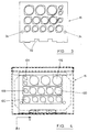
- the panel 14 includes a plurality of male connectors 12A, 12B, 12C, 12D of varying diameter with the connectors 12 having different electrical or non electrical function and with some of the male connectors possibly having a different number of pins or perhaps some dummy pins that serve no function.
- Figure 4 shows a front view of a rack panel 16 that includes female connectors 10A, 10B, 10C, 10D and 10E that are aligned with the corresponding male connectors on the panel 14 whereby movement of the rack panel towards the box panel effects connection of all male and female connectors on the panel in one movement.
- the rack panel 16 is mounted on slides (not shown) that cooperate with recess 32 formed in the lower surface of the panel 16, seen in Figure 3.
- the other peripheral surfaces of the panel 16 may also slide along guide surfaces in order that, when the rack panel 16 is pushed towards the panel 14 each of the connections are substantially correctly aligned.
- the slides and guides could be provided separately from the box panel. Alternatively those slides and guides could be integral and part of the box panel, for instance by housing a hood extending forwardly from the box panel within which the rack panel is received.
- each other openings 34 on the rack panel (only two of which are shown) are brought over the threaded end of studs 35 that project forwardly from the box panel which may assist in the alignment of the panels. Then the panels are manually pushed together, possibly all the way home or possibly only partially. Then the ends of the studs 35 that now extend through the rack panel are engaged by threaded members (not shown) whereby tightening of the threaded members (possibly in turn or together) keeps the panels together or urges the panels to their final relative position.
- the female connectors are mounted on their panel by springs 36 (described later) to bias each connector towards the rack panel. Accordingly as the threaded studs bring the rack panel home, the female connectors can move axially against that spring bias such that the connectors are both held together and urged together by the springs.
- the studs can have enlarged abutments against which the rack panel bears to resist movement of the panels towards each other and to allow tightening of the threaded members to a considerable extent without undue force being exerted on each individual connector.
- any eccentricity of the housings causes the fixed male housing to bear against the side walls of the female housing as the two are pushed together to cause the female housing to shift translationally in the "X" and "Y” direction, as required.
- the guide channels 26 of the male housing also diverge circumferentially outwardly in their outer extent. This allows the lugs 28 on the female member to start off slightly misaligned but to bear against the axial side walls of the channels upon movement of the connectors towards each other to cause limited relative rotational movement of the connectors to thereby correctly align the connectors.
- the female connector includes a rear portion 38 comprising an outer threaded portion 40 for connecting to other parts of the connector in a manner that is well known and an enlarged flange 42.
- the connector is pushed through an opening 44 (see Figure 1) in the panel 16 until the front of the flange 42 abuts the panel.
- the connector includes a cylindrical portion 46 that lies within the panel opening with there being a gap between the cylindrical portion 46 and the wall of the panel defining the opening in the panel to permit the two parts to move in the X and Y direction relative to each other.
- the flange 42 also includes forwardly extending cylindrical lugs 48 on diametrically opposite sides of the opening 44 which lugs 48 extend into slots 50 in the panel 16.
- the slots 50 extend radially out from the opening.
- the slots 50 are of slightly greater dimension than the lugs 48 such that translational movement of the connector can occur in the X and Y direction and also a restricted amount of rotational movement around the Z axis can occur.
- a shim 52 is slid along the connector to bear against the front of the panel followed by the annular sinusoidal disc spring 36, a further shim 54 and then a circlip 56 that is held axially in a groove (not shown) in the connector such that the spring 36 in always under slight flexure.
- the connector can move to the right relative to the panel on which it is mounted in the Z direction, against the bias of the spring 36.
- Each female electrical connector is also provided with its own electro magnetic compatibility protection spring 62, as seen in Figure 8, that is located axially between spaced flanges 64. These flanges 64 also each have the lugs 28 axially aligned with each other.
- the protection spring 62 shields each connector in a panel off from every other connector.
- the male connector mounting on the panel 14 is shown in Figures 5 and 6.
- the connector has an enlarged flange that abuts the panel 14 either at front or rear surface of the panel.
- the flange includes four openings 60. Bolts can be pushed through these openings 60, and aligned openings in the panel, with nuts then being used to fix the connectors firmly to the panel 14.
- Figure 9 shows the different sizes and types of connectors that can be brought together simultaneously by the panels 14 and 16 with a gas connector 60 being shown at the bottom and with the other connectors being electrical.
Landscapes
- Details Of Connecting Devices For Male And Female Coupling (AREA)
Abstract
Description
Claims (15)
- A connector arrangement including a first part (14) and a second part (16), each part comprising at least one connector portion (12A,12B,12C,12D,10A,10B,10C,10D,10E) with the connector portion on one part being arranged to cooperate with the connector portion on the other part upon relative movement of one part relative to the other in a first direction in which the first part has its connector portion mounted thereon whereby the connector portion of the first part is able to move relative to the first part.
- An arrangement as claimed in Claim 1 in which the connector portion of the first part is able to move in a direction transverse to the extent of the first direction.
- An arrangement as claimed in Claim 2 in which the connector portion of the first part extends through an opening in the first part such that the connector portion is able to move in the opening relative to the first part in a direction transverse to the first direction.
- An arrangement as claimed in Claim 1, 2 or 3 in which the relative movement of the connector portion of the first part to the first part is translational movement.
- An arrangement as claimed in any preceding claim in which the relative movement of the connector portion of the first part to the first part is generally in line with the first direction.
- An arrangement as claimed in Claim 5 in which the relative movement of the connector portion of the first part to the first part is against a resilient bias.
- An arrangement as claimed in any preceding claim in which the relative movement of the connector portion of the first part to the first part is arranged to be arcuate movement generally about the extent of the first direction.
- An arrangement as claimed in any preceding claim in which the connector portion of the first part and the first part are arranged to cooperate to restrict relative rotational movement of those parts generally about the extent of the first direction.
- An arrangement as claimed in any preceding claim in which the movement of the connector portion of the first part relative to the first part is arranged to be caused by abutment of the connector portion of the first part with a connector portion of the second part.
- An arrangement as claimed in any preceding claim in which the first part includes a plurality of connector portions each of which are mounted such that they can move separately relative to each other.
- A method of connecting a first part and a second part in which each part includes at least one connector portion, the method comprising moving one of the parts towards the other part such that the connector portions on each part become connected with the connector portion of the first part moving relative to the first part during the relative movement of the first and second parts.
- A method as claimed in Claim 11 in which the movement of the connector portion on the first part relative to the first part is effected upon a connector arrangement as claimed in any of Claims 1 to 10.
- A method as claimed in Claim 11 or 12 comprising a plurality of connector portions on the first part each moving relative to the first part when the first part and the second part move towards each other to connect the connector portions of the respective parts.
- A method as claimed in Claim 13 comprising the connector portions on the first part each moving relative to each other and relative to the first part during relative movement of the first and second parts to connect their respective connector portions.
- A method as claimed in any of Claims 11 to 14 including a guide for one of the first or second parts whereby movement of that part along the guide moves that part accurately towards the other part.
Applications Claiming Priority (2)
| Application Number | Priority Date | Filing Date | Title |
|---|---|---|---|
| GB9715378A GB9715378D0 (en) | 1997-07-23 | 1997-07-23 | Connector assemblies |
| GB9715378 | 1997-07-23 |
Publications (2)
| Publication Number | Publication Date |
|---|---|
| EP0893856A2 true EP0893856A2 (en) | 1999-01-27 |
| EP0893856A3 EP0893856A3 (en) | 1999-12-08 |
Family
ID=10816217
Family Applications (1)
| Application Number | Title | Priority Date | Filing Date |
|---|---|---|---|
| EP98305840A Withdrawn EP0893856A3 (en) | 1997-07-23 | 1998-07-22 | Connector assemblies |
Country Status (2)
| Country | Link |
|---|---|
| EP (1) | EP0893856A3 (en) |
| GB (2) | GB9715378D0 (en) |
Cited By (8)
| Publication number | Priority date | Publication date | Assignee | Title |
|---|---|---|---|---|
| WO2001056118A3 (en) * | 2000-01-29 | 2002-04-25 | Zahnradfabrik Friedrichshafen | Electric connector |
| WO2007107511A1 (en) * | 2006-03-17 | 2007-09-27 | Airbus Deutschland Gmbh | Fastening system for fastening a cabin fitting element to a support structure of an aircraft |
| EP2045882A1 (en) * | 2007-10-02 | 2009-04-08 | AMPHENOL-TUCHEL ELECTRONICS GmbH | Self-adjusting device connector |
| DE102005026148B4 (en) * | 2005-06-06 | 2012-06-06 | Intercontec Pfeiffer Industrie-Steckverbindungen Gmbh | connector female |
| CN103579869A (en) * | 2012-07-30 | 2014-02-12 | 联合机械株式会社 | Electric connector used for molding wiring board |
| DE202015009096U1 (en) | 2015-11-06 | 2016-10-24 | Amphenol-Tuchel Electronics Gmbh | Circular connector with tolerance compensation means |
| US11417989B2 (en) * | 2020-03-12 | 2022-08-16 | Koninklijke Fabriek Inventum B.V. | Galley insert power connector assembly with spring assemblies |
| DE102021105914A1 (en) | 2021-03-11 | 2022-09-15 | Marquardt Gmbh | High-voltage management system, especially for vehicle energy storage |
Family Cites Families (8)
| Publication number | Priority date | Publication date | Assignee | Title |
|---|---|---|---|---|
| NL266688A (en) * | 1960-07-08 | |||
| US4580862A (en) * | 1984-03-26 | 1986-04-08 | Amp Incorporated | Floating coaxial connector |
| US4697859A (en) * | 1986-08-15 | 1987-10-06 | Amp Incorporated | Floating coaxial connector |
| JPH0527814Y2 (en) * | 1988-02-09 | 1993-07-15 | ||
| US4812133A (en) * | 1988-06-30 | 1989-03-14 | Amp Incorporated | Floating mounting means for electrical connector assembly |
| IT1223957B (en) * | 1988-11-30 | 1990-09-29 | Magneti Marelli Spa | VALVE GROUP FOR BRAKING CONTROL OF A TRAILER VEHICLE AND BRAKING SYSTEM INCLUDING SUCH VALVE GROUP |
| FR2685825B1 (en) * | 1991-12-26 | 1994-04-01 | Ecia | SELF-CENTERING AUTOMATIC CONNECTOR. |
| US6017233A (en) * | 1994-12-14 | 2000-01-25 | Molex Incorporated | Floating panel mount system for electrical connectors |
-
1997
- 1997-07-23 GB GB9715378A patent/GB9715378D0/en active Pending
-
1998
- 1998-07-22 EP EP98305840A patent/EP0893856A3/en not_active Withdrawn
- 1998-07-22 GB GB9815866A patent/GB2330018A/en active Pending
Cited By (12)
| Publication number | Priority date | Publication date | Assignee | Title |
|---|---|---|---|---|
| WO2001056118A3 (en) * | 2000-01-29 | 2002-04-25 | Zahnradfabrik Friedrichshafen | Electric connector |
| US6685493B2 (en) | 2000-01-29 | 2004-02-03 | Zf Friedrichshafen Ag | Electric connector |
| DE102005026148B4 (en) * | 2005-06-06 | 2012-06-06 | Intercontec Pfeiffer Industrie-Steckverbindungen Gmbh | connector female |
| WO2007107511A1 (en) * | 2006-03-17 | 2007-09-27 | Airbus Deutschland Gmbh | Fastening system for fastening a cabin fitting element to a support structure of an aircraft |
| US8167624B2 (en) | 2006-03-17 | 2012-05-01 | Airbus Operations Gmbh | Fastening system for fastening a cabin fitting element to a support structure of an aircraft |
| EP2045882A1 (en) * | 2007-10-02 | 2009-04-08 | AMPHENOL-TUCHEL ELECTRONICS GmbH | Self-adjusting device connector |
| CN103579869A (en) * | 2012-07-30 | 2014-02-12 | 联合机械株式会社 | Electric connector used for molding wiring board |
| CN103579869B (en) * | 2012-07-30 | 2018-01-30 | 联合机械株式会社 | Shape the electrical fitting of distributing board |
| DE202015009096U1 (en) | 2015-11-06 | 2016-10-24 | Amphenol-Tuchel Electronics Gmbh | Circular connector with tolerance compensation means |
| DE102015119068A1 (en) | 2015-11-06 | 2017-06-01 | Amphenol-Tuchel Electronics Gmbh | Circular connector with tolerance compensation means |
| US11417989B2 (en) * | 2020-03-12 | 2022-08-16 | Koninklijke Fabriek Inventum B.V. | Galley insert power connector assembly with spring assemblies |
| DE102021105914A1 (en) | 2021-03-11 | 2022-09-15 | Marquardt Gmbh | High-voltage management system, especially for vehicle energy storage |
Also Published As
| Publication number | Publication date |
|---|---|
| GB9715378D0 (en) | 1997-09-24 |
| GB9815866D0 (en) | 1998-09-16 |
| GB2330018A (en) | 1999-04-07 |
| EP0893856A3 (en) | 1999-12-08 |
Similar Documents
| Publication | Publication Date | Title |
|---|---|---|
| US5266047A (en) | Electrical connector assembly | |
| EP0961362B1 (en) | Connector mounting structure | |
| KR101467722B1 (en) | Header assembly | |
| EP0330231B1 (en) | Plug-in connector | |
| US7588461B2 (en) | Mating connectors with a continuous EMI shield | |
| EP0863579A2 (en) | Circular bulkhead connector assembly | |
| CN1667441B (en) | Plug housing for industrial application | |
| JP2003014981A (en) | Fiber optic adapter | |
| US8287297B2 (en) | Clearance compensation unit | |
| EP2276122B1 (en) | Lever-type connector | |
| US8403702B2 (en) | Releasable electrical connector adaptor and assembly | |
| GB2193853A (en) | Floating coaxial connector | |
| US6358075B1 (en) | Mating alignment guide | |
| JPS63291373A (en) | Elastic latch and assembly for electric connector and its system | |
| CA2756189A1 (en) | Rf connector assembly | |
| EP0893856A2 (en) | Connector assemblies | |
| JP2022547590A (en) | Quick connect electrical connector system | |
| JP2017004949A (en) | Locking device for electric connector | |
| US7942697B2 (en) | Electrical interconnection systems and methods of assembling the same | |
| EP0366353B1 (en) | Electrical test equipment | |
| US4509814A (en) | Electrical connector shell assembly with continuous annular seal | |
| US6918702B2 (en) | Optical connector system | |
| EP1298470B1 (en) | Optical connector system | |
| KR20250137662A (en) | Connector disengagement resistance mechanism | |
| US10938429B1 (en) | Universal receiver |
Legal Events
| Date | Code | Title | Description |
|---|---|---|---|
| PUAI | Public reference made under article 153(3) epc to a published international application that has entered the european phase |
Free format text: ORIGINAL CODE: 0009012 |
|
| AK | Designated contracting states |
Kind code of ref document: A2 Designated state(s): AT BE CH CY DE DK ES FI FR GB GR IE IT LI LU MC NL PT SE |
|
| AX | Request for extension of the european patent |
Free format text: AL;LT;LV;MK;RO;SI |
|
| PUAL | Search report despatched |
Free format text: ORIGINAL CODE: 0009013 |
|
| AK | Designated contracting states |
Kind code of ref document: A3 Designated state(s): AT BE CH CY DE DK ES FI FR GB GR IE IT LI LU MC NL PT SE |
|
| AX | Request for extension of the european patent |
Free format text: AL;LT;LV;MK;RO;SI |
|
| AKX | Designation fees paid | ||
| REG | Reference to a national code |
Ref country code: DE Ref legal event code: 8566 |
|
| STAA | Information on the status of an ep patent application or granted ep patent |
Free format text: STATUS: THE APPLICATION IS DEEMED TO BE WITHDRAWN |
|
| 18D | Application deemed to be withdrawn |
Effective date: 20000609 |