EP0894185B1 - Ventilsteuersystem - Google Patents
Ventilsteuersystem Download PDFInfo
- Publication number
- EP0894185B1 EP0894185B1 EP97916272A EP97916272A EP0894185B1 EP 0894185 B1 EP0894185 B1 EP 0894185B1 EP 97916272 A EP97916272 A EP 97916272A EP 97916272 A EP97916272 A EP 97916272A EP 0894185 B1 EP0894185 B1 EP 0894185B1
- Authority
- EP
- European Patent Office
- Prior art keywords
- cam
- cam follower
- timing system
- valve timing
- variable valve
- Prior art date
- Legal status (The legal status is an assumption and is not a legal conclusion. Google has not performed a legal analysis and makes no representation as to the accuracy of the status listed.)
- Expired - Lifetime
Links
- 239000011435 rock Substances 0.000 claims 1
- 238000002485 combustion reaction Methods 0.000 abstract description 6
- 241000282326 Felis catus Species 0.000 abstract 1
- 230000015572 biosynthetic process Effects 0.000 description 4
- 230000000295 complement effect Effects 0.000 description 4
- WJOHZNCJWYWUJD-IUGZLZTKSA-N Fluocinonide Chemical compound C1([C@@H](F)C2)=CC(=O)C=C[C@]1(C)[C@]1(F)[C@@H]2[C@@H]2C[C@H]3OC(C)(C)O[C@@]3(C(=O)COC(=O)C)[C@@]2(C)C[C@@H]1O WJOHZNCJWYWUJD-IUGZLZTKSA-N 0.000 description 1
- 238000000034 method Methods 0.000 description 1
- 238000012986 modification Methods 0.000 description 1
- 230000004048 modification Effects 0.000 description 1
- 229940052996 vanos Drugs 0.000 description 1
Images


Classifications
-
- F—MECHANICAL ENGINEERING; LIGHTING; HEATING; WEAPONS; BLASTING
- F01—MACHINES OR ENGINES IN GENERAL; ENGINE PLANTS IN GENERAL; STEAM ENGINES
- F01L—CYCLICALLY OPERATING VALVES FOR MACHINES OR ENGINES
- F01L1/00—Valve-gear or valve arrangements, e.g. lift-valve gear
- F01L1/12—Transmitting gear between valve drive and valve
- F01L1/14—Tappets; Push rods
- F01L1/143—Tappets; Push rods for use with overhead camshafts
-
- F—MECHANICAL ENGINEERING; LIGHTING; HEATING; WEAPONS; BLASTING
- F01—MACHINES OR ENGINES IN GENERAL; ENGINE PLANTS IN GENERAL; STEAM ENGINES
- F01L—CYCLICALLY OPERATING VALVES FOR MACHINES OR ENGINES
- F01L1/00—Valve-gear or valve arrangements, e.g. lift-valve gear
- F01L1/02—Valve drive
- F01L1/04—Valve drive by means of cams, camshafts, cam discs, eccentrics or the like
- F01L1/08—Shape of cams
-
- F—MECHANICAL ENGINEERING; LIGHTING; HEATING; WEAPONS; BLASTING
- F01—MACHINES OR ENGINES IN GENERAL; ENGINE PLANTS IN GENERAL; STEAM ENGINES
- F01L—CYCLICALLY OPERATING VALVES FOR MACHINES OR ENGINES
- F01L13/00—Modifications of valve-gear to facilitate reversing, braking, starting, changing compression ratio, or other specific operations
- F01L13/0015—Modifications of valve-gear to facilitate reversing, braking, starting, changing compression ratio, or other specific operations for optimising engine performances by modifying valve lift according to various working parameters, e.g. rotational speed, load, torque
- F01L13/0031—Modifications of valve-gear to facilitate reversing, braking, starting, changing compression ratio, or other specific operations for optimising engine performances by modifying valve lift according to various working parameters, e.g. rotational speed, load, torque by modification of tappet or pushrod length
-
- F—MECHANICAL ENGINEERING; LIGHTING; HEATING; WEAPONS; BLASTING
- F01—MACHINES OR ENGINES IN GENERAL; ENGINE PLANTS IN GENERAL; STEAM ENGINES
- F01L—CYCLICALLY OPERATING VALVES FOR MACHINES OR ENGINES
- F01L2307/00—Preventing the rotation of tappets
Definitions
- the present invention relates to a power output improvement apparatus for an internal combustion engine and in particular to a valve timing system for an internal combustion engine, which is also applicable to engines having multi-inlet and multi-exhaust configurations per combustion chamber.
- EP-A-0292185 discloses a cam mechanism which includes a cam of basic circular formation and having a lobe formation extending radially outwardly along part ofits periphery; and a cam follower mounted for reciprocating movement along an axis perpendicular to the axis of rotation of the cam.
- the cam acts against an end face of the cam follower so that engagement of the lobe formation therewith will cause movement of the cam follower.
- the inclination of the face of the cam follower which is engaged by the lobe formation is adjustable to vary the duration of movement of the cam follower by the cam.
- the present invention provides a variable valve timing system as set out in the claims appended hereto.
- the cam (1) has a contoured outer or contact surface (2).
- the contour can be of any desired profile, but is preferably v-shaped.
- the cam (1) is supported on the cam shaft (3) as is normal with internal combustion engines.
- the cam follower (4) operates the valve (not shown), and has a contoured upper engagement surface (5) of any desired configuration. However, preferably the contour of the upper engagement surface (5) of the cam follower (4) and the contoured contact surface (2) of the cam (1) are complementary. As illustrated, the contour on the upper surface (5) of the cam follower (4) is a v-shaped recess (6), with the walls thereof at any desired angle.
- this timing system is the same as any standard timing system, in that as the cam shaft rotates at a speed determined by the engine speed such as at half the engine speed, the cam rotates around the cam shaft axis and the cam engagement surface on the lobe engages the cam follower, opening and closing the valve.
- the cam follower (4) is rotated about its axis (7) a desired number of degrees as shown in Figure 3, in accordance with the engine speed.
- the v-shaped recess (6) and the complementary v-shaped contact surface (2) of the cam (1) are slightly out of alignment, so that the contact surface (2) of the cam lobe engages the inclined plane of the wall of the v-shaped recess (6) at a higher point, hence earlier in the cycle and disengage later, than when the v-shaped recess (6) and the complementary v-shaped contact surface (2) of the cam (1) are aligned. Therefore the valve is opened sooner and closed later, increasing the degrees of the cycle for which the valve is open, as the engine revolutions increase.
- two rocker inserts (8) are located in the v-shaped recess (6), to maintain the geometric integrity of the alignment of the contact faces of the cam (1) and cam follower (4), to lessen wear on the cam (1).
- the rocker inserts (8) are fitted into the cam follower (4) so that they can rotate about their respective axes (9 & 10), as they are engaged by the contoured contact surface (2) of the cam (1) during the rotation of the cam (1) and the reciprocated rotation of the cam follower (4).
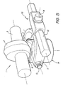
- FIG. 4 One method of rotating the cam follower (4) is shown in figures 4 & 5, wherein a control yoke (11) is pivotally attached, at one end, connected by two bolts (13) to the cam follower (4) and at its other end to a control rod (12).
- the yoke (11) is connected by a shaft (14) to a floating ball assembly (15) in the control rod (12).
- Adjustment of the angular positions of the cam followers (4) is carried out by means of an adjustment nut (16) which has a left hand threaded rod (17) and a right handed threaded rod (18) which engage in control rod (12).
- the movement of the control rod (12) could be computer controlled by the engine revolutions or the driving mode or centrifugally controlled.
- the rocker inserts (8) have their ends (19) which slide into respective grooves (20), to prevent the inserts (8) from falling out of their recesses (21).
- each engaging surface of the two rocker inserts of a particular cam follower and the respective complementary engaging surfaces of the cam could be different so that the valve is allowed to advance forward but with less delay in closing or with no delay in closing or vice versa.
- the engaging surfaces of the rocker inserts could slope from the periphery of the cam follower to the centre line (26) of the cam follower (4) ⁇ fig. 3 ⁇
- an embodiment of the present invention is applicable to push rod engines.
- the control of the operation of the cam followers (4) and the cams (1) are the same as the other embodiments.
- camshaft (3), cam followers (4) and controls be located in a single assembly , which can be removed, as a whole, from the engine.
- Figure 7 shows a paired inlet and outlet valve arrangement.
- the cam follower centre (7) is offset from the valve stem centre (23).
- a semi circular groove (24) is milled in the underside (25) of the cam follower (4) to take up the rotation of the cam follower (4) relative to the valve stem (27).
- the semi circular groove (24) can be milled to varying depths so that when the cam follower is rotated, the tappet clearance is maintained.
Landscapes
- Engineering & Computer Science (AREA)
- Mechanical Engineering (AREA)
- General Engineering & Computer Science (AREA)
- Valve Device For Special Equipments (AREA)
- Valve-Gear Or Valve Arrangements (AREA)
- Synchronisation In Digital Transmission Systems (AREA)
- Grinding Of Cylindrical And Plane Surfaces (AREA)
- Acyclic And Carbocyclic Compounds In Medicinal Compositions (AREA)
Claims (6)
- Variables Ventiltriebsystem, umfassend:dadurch gekennzeichnet, dass zwei Kipphebeleinsätze (8) die Eingriffsfläche (5) des Nockenstößels (4) bilden, wobei die genannten Kipphebeleinsätze (8) jeweils ausgeführt sind, um bei der Drehung des genannten Nockenstößels (4) relativ zur genannten Bewegungsebene des genannten Nockens (1) um eine Längsachse gekippt zu werden.einen Nockenstößel (4) zum Bewegen eines Ventils zwischen seiner geschlossenen und seiner offenen Stellung, wobei der genannte Stößel (4) eine profilierte Eingriffsfläche (5) hat;einen Nocken (1), der sich auf einer Nockenwelle (3) befindet und von ihr angetrieben wird und der eine Kontaktfläche (2) zum Eingriff in der Eingriffsfläche (5) des Nockenstößels (4) und zum Bewegen des Nockenstößels (4) zum Betätigen des Ventils hat, wobei die Kontaktfläche (2) des Nockens (1) an wenigstens einem Teil davon entlang profiliert ist; undeine Drehvorrichtung zum Drehen des Nockenstößels (4) relativ zur Bewegungsebene des Nockens (1) auf eine gedrehte Stellung, sodass die profilierte Kontaktfläche (2) des Nockens (1) und die profilierte Eingriffsfläche (5) des Nockenstößels (4) während der Drehbewegung des Nockens (1) früher miteinander in Eingriff kommen und später getrennt werden als dann, wenn der Nockenstößel (4) in einer nicht gedrehten Stellung ist;
- Variables Ventiltriebsystem nach Anspruch 1, dadurch gekennzeichnet, dass das von den zwei Kipphebeleinsätzen (8) gebildete Profil der Nockenstößel-Eingriffsfläche (5) im Schnitt V-förmig ist.
- Variables Ventiltriebsystem nach Anspruch 1, dadurch gekennzeichnet, dass die Kipphebeleinsätze (8) sich im Nockenstößel (4) in Ausnehmungen (21) befinden, die Nuten (20) haben, in die die Enden der Kipphebeleinsätze (8) gleiten, um die Kipphebeleinsätze (8) in den jeweiligen Ausnehmungen (21) zu halten.
- Variables Ventiltriebsystem nach Anspruch 1, dadurch gekennzeichnet, dass die genannte Drehvorrichtung eine Regelstange (12) umfasst und jeder genannte Nockenstößel (4) zwischen den Schenkeln eines allgemein U-förmigen Jochs (11) gehalten wird, wobei jedes genannte Joch (11) schwenkbar mit der genannten Regelstange (12) verbunden ist.
- Variables Ventiltriebsystem nach Anspruch 4, dadurch gekennzeichnet, dass jedes genannte Joch (11) über eine Schwebekugelanordnung (15) schwenkbar mit der genannten Regelstange (12) verbunden ist.
- Variables Ventiltriebsystem nach Anspruch 5, dadurch gekennzeichnet, dass die Regelstange (12) ein Mittel (16) zum Verstellen ihrer Länge jeweils zwischen den Schwebekugelanordnung (15) hat, um den Nocken (1) nach Bedarf auf den Nockenstößel (4) auszurichten.
Applications Claiming Priority (4)
| Application Number | Priority Date | Filing Date | Title |
|---|---|---|---|
| AUPN9265/96 | 1996-04-16 | ||
| AUPN9265A AUPN926596A0 (en) | 1996-04-16 | 1996-04-16 | Valve timing system |
| AUPN926596 | 1996-04-16 | ||
| PCT/AU1997/000237 WO1997039222A1 (en) | 1996-04-16 | 1997-04-16 | Valve timing system |
Publications (3)
| Publication Number | Publication Date |
|---|---|
| EP0894185A1 EP0894185A1 (de) | 1999-02-03 |
| EP0894185A4 EP0894185A4 (de) | 2001-09-19 |
| EP0894185B1 true EP0894185B1 (de) | 2004-02-18 |
Family
ID=3793579
Family Applications (1)
| Application Number | Title | Priority Date | Filing Date |
|---|---|---|---|
| EP97916272A Expired - Lifetime EP0894185B1 (de) | 1996-04-16 | 1997-04-16 | Ventilsteuersystem |
Country Status (9)
| Country | Link |
|---|---|
| US (1) | US6386159B1 (de) |
| EP (1) | EP0894185B1 (de) |
| JP (1) | JP3993238B2 (de) |
| AT (1) | ATE259933T1 (de) |
| AU (1) | AUPN926596A0 (de) |
| CA (1) | CA2251836C (de) |
| DE (1) | DE69727663T2 (de) |
| NZ (1) | NZ332370A (de) |
| WO (1) | WO1997039222A1 (de) |
Families Citing this family (7)
| Publication number | Priority date | Publication date | Assignee | Title |
|---|---|---|---|---|
| GB0309699D0 (en) * | 2003-04-28 | 2003-06-04 | Delphi Tech Inc | Improvements in cams and cam followers |
| US20060196459A1 (en) * | 2005-03-01 | 2006-09-07 | Manousos Pattakos | Discrete mode variable valve gear |
| US7506624B2 (en) | 2006-02-28 | 2009-03-24 | Perkins Engines Company Limited | Variable engine valve actuation system |
| LV13993B (lv) * | 2008-02-21 | 2010-01-20 | Motorcikls, Sia | Ierīce iekšdedzes dzinēja gāzu sadales fāžu regulēšanai |
| DE102011106395A1 (de) * | 2011-07-02 | 2013-01-03 | Man Truck & Bus Ag | Ventilsteuerung für mindestens ein Ventil einer Brennkraftmaschine |
| CN105464733A (zh) * | 2015-12-08 | 2016-04-06 | 长春设备工艺研究所 | 一种用于发动机凸轮驱动的凹球面圆弧凸轮结构 |
| WO2018013461A1 (en) * | 2016-07-14 | 2018-01-18 | Borgwarner Inc. | Valve actuation system providing variable valve lift |
Family Cites Families (12)
| Publication number | Priority date | Publication date | Assignee | Title |
|---|---|---|---|---|
| US1501041A (en) * | 1922-01-25 | 1924-07-15 | Henry H Cutler | Internal-combustion engine |
| US2663288A (en) * | 1952-09-02 | 1953-12-22 | Loyd F Ashley | Variable timing cam follower |
| US4399784A (en) * | 1981-02-10 | 1983-08-23 | Foley James E | Internal combustion engine |
| IT1159352B (it) * | 1983-03-07 | 1987-02-25 | Fiat Auto Spa | Dispositivo di regolazione della posizione assiale di un albero a camme a profilo variabile particolarmente per il comando della distribuzione di un motore |
| GB2165018B (en) | 1984-08-02 | 1988-12-29 | Lonrho Plc | Poppet valve arrangements |
| GB2207968B (en) | 1984-10-26 | 1989-07-26 | Lonrho Plc | Arrangements for converting rotary motion to linear motion |
| DE3503740A1 (de) | 1985-02-05 | 1986-08-07 | Miklos Dipl.-Ing. 6800 Mannheim Csongrady | Vorrichtung zur veraenderung der steuerzeiten bei ventilgesteuerten verbrennungsmotoren |
| IT1182480B (it) * | 1985-07-02 | 1987-10-05 | Fiat Auto Spa | Sistema di punteria per motori a combustione interna provvisti di alberi con camme a profilo variabile |
| GB8711993D0 (en) * | 1987-05-21 | 1987-06-24 | Jaguar Cars | Cam mechanisms |
| US4850311A (en) * | 1988-12-09 | 1989-07-25 | General Motors Corporation | Three dimensional cam cardanic follower valve lifter |
| EP0452671B1 (de) * | 1990-03-14 | 1995-06-14 | Suzuki Kabushiki Kaisha | Ventiltriebvorrichtung für Viertaktbrennkraftmaschine |
| JPH08121118A (ja) | 1994-10-24 | 1996-05-14 | Yamaha Motor Co Ltd | 4サイクルエンジン |
-
1996
- 1996-04-16 AU AUPN9265A patent/AUPN926596A0/en not_active Abandoned
-
1997
- 1997-04-16 NZ NZ332370A patent/NZ332370A/en not_active IP Right Cessation
- 1997-04-16 WO PCT/AU1997/000237 patent/WO1997039222A1/en not_active Ceased
- 1997-04-16 CA CA002251836A patent/CA2251836C/en not_active Expired - Fee Related
- 1997-04-16 JP JP53659097A patent/JP3993238B2/ja not_active Expired - Lifetime
- 1997-04-16 EP EP97916272A patent/EP0894185B1/de not_active Expired - Lifetime
- 1997-04-16 US US09/171,363 patent/US6386159B1/en not_active Expired - Lifetime
- 1997-04-16 DE DE69727663T patent/DE69727663T2/de not_active Expired - Lifetime
- 1997-04-16 AT AT97916272T patent/ATE259933T1/de not_active IP Right Cessation
Also Published As
| Publication number | Publication date |
|---|---|
| DE69727663T2 (de) | 2004-12-23 |
| JP3993238B2 (ja) | 2007-10-17 |
| EP0894185A4 (de) | 2001-09-19 |
| JP2000509455A (ja) | 2000-07-25 |
| CA2251836C (en) | 2005-07-05 |
| CA2251836A1 (en) | 1997-10-23 |
| ATE259933T1 (de) | 2004-03-15 |
| WO1997039222A1 (en) | 1997-10-23 |
| NZ332370A (en) | 2000-06-23 |
| EP0894185A1 (de) | 1999-02-03 |
| US6386159B1 (en) | 2002-05-14 |
| AUPN926596A0 (en) | 1996-05-09 |
| DE69727663D1 (de) | 2004-03-25 |
Similar Documents
| Publication | Publication Date | Title |
|---|---|---|
| US6357405B1 (en) | Valve drive mechanism of four-stroke cycle engine | |
| EP0108238B1 (de) | Stössel für Brennkraftmaschinen mit Nockenwellen mit variablen Nockenprofilen | |
| US4693214A (en) | Tappet system for internal combustion engines having shafts with variable-profile cams | |
| USRE33787E (en) | Four-cycle engine | |
| US5555860A (en) | Valve control mechanism | |
| EP0601570B1 (de) | Ventiltrieb für Brennkraftmaschine | |
| US6170449B1 (en) | Valve operating system for engine | |
| EP0179581A2 (de) | Ventilantrieb mit variablen Steuerzeiten | |
| EP0963508B1 (de) | Stellvorrichtung für ventile | |
| EP0894185B1 (de) | Ventilsteuersystem | |
| US6386161B2 (en) | Cam link variable valve mechanism | |
| US5245957A (en) | Spring assist system for internal combustion engine valves | |
| AU734474B2 (en) | Valve timing system | |
| US4387674A (en) | Valve train | |
| KR100501461B1 (ko) | 밸브타이밍장치 | |
| US7546823B2 (en) | Variable overhead valve control for engines | |
| US20220298932A1 (en) | Internal combustion engine with camshaft valve phase variation device | |
| EP0936346A2 (de) | Nockenkontur in einer Ventilbetätigungsvorrichtung | |
| US6655330B2 (en) | Offset variable valve actuation mechanism | |
| US20030159667A1 (en) | Adjustment mechanism for valves | |
| JPH027202Y2 (de) | ||
| GB1604605A (en) | Valve gear of internal combustion engines | |
| JPH0454043B2 (de) | ||
| AU9747301A (en) | Adjustment mechanism for valves | |
| JPH04116208A (ja) | エンジンのバルブクリアランス調整装置 |
Legal Events
| Date | Code | Title | Description |
|---|---|---|---|
| PUAI | Public reference made under article 153(3) epc to a published international application that has entered the european phase |
Free format text: ORIGINAL CODE: 0009012 |
|
| 17P | Request for examination filed |
Effective date: 19981116 |
|
| AK | Designated contracting states |
Kind code of ref document: A1 Designated state(s): AT BE CH DE DK ES FR GB IT LI LU NL SE |
|
| A4 | Supplementary search report drawn up and despatched |
Effective date: 20010803 |
|
| AK | Designated contracting states |
Kind code of ref document: A4 Designated state(s): AT BE CH DE DK ES FR GB IT LI LU NL SE |
|
| RIC1 | Information provided on ipc code assigned before grant |
Free format text: 7F 01L 1/04 A, 7F 01L 13/00 B, 7F 01L 31/14 B |
|
| 17Q | First examination report despatched |
Effective date: 20021029 |
|
| GRAP | Despatch of communication of intention to grant a patent |
Free format text: ORIGINAL CODE: EPIDOSNIGR1 |
|
| GRAS | Grant fee paid |
Free format text: ORIGINAL CODE: EPIDOSNIGR3 |
|
| GRAA | (expected) grant |
Free format text: ORIGINAL CODE: 0009210 |
|
| AK | Designated contracting states |
Kind code of ref document: B1 Designated state(s): AT BE CH DE DK ES FR GB IT LI LU NL SE |
|
| PG25 | Lapsed in a contracting state [announced via postgrant information from national office to epo] |
Ref country code: NL Free format text: LAPSE BECAUSE OF FAILURE TO SUBMIT A TRANSLATION OF THE DESCRIPTION OR TO PAY THE FEE WITHIN THE PRESCRIBED TIME-LIMIT Effective date: 20040218 Ref country code: LI Free format text: LAPSE BECAUSE OF FAILURE TO SUBMIT A TRANSLATION OF THE DESCRIPTION OR TO PAY THE FEE WITHIN THE PRESCRIBED TIME-LIMIT Effective date: 20040218 Ref country code: CH Free format text: LAPSE BECAUSE OF FAILURE TO SUBMIT A TRANSLATION OF THE DESCRIPTION OR TO PAY THE FEE WITHIN THE PRESCRIBED TIME-LIMIT Effective date: 20040218 Ref country code: BE Free format text: LAPSE BECAUSE OF FAILURE TO SUBMIT A TRANSLATION OF THE DESCRIPTION OR TO PAY THE FEE WITHIN THE PRESCRIBED TIME-LIMIT Effective date: 20040218 Ref country code: AT Free format text: LAPSE BECAUSE OF FAILURE TO SUBMIT A TRANSLATION OF THE DESCRIPTION OR TO PAY THE FEE WITHIN THE PRESCRIBED TIME-LIMIT Effective date: 20040218 |
|
| REG | Reference to a national code |
Ref country code: GB Ref legal event code: FG4D |
|
| REG | Reference to a national code |
Ref country code: CH Ref legal event code: EP |
|
| REF | Corresponds to: |
Ref document number: 69727663 Country of ref document: DE Date of ref document: 20040325 Kind code of ref document: P |
|
| PG25 | Lapsed in a contracting state [announced via postgrant information from national office to epo] |
Ref country code: LU Free format text: LAPSE BECAUSE OF NON-PAYMENT OF DUE FEES Effective date: 20040416 |
|
| PG25 | Lapsed in a contracting state [announced via postgrant information from national office to epo] |
Ref country code: DK Free format text: LAPSE BECAUSE OF FAILURE TO SUBMIT A TRANSLATION OF THE DESCRIPTION OR TO PAY THE FEE WITHIN THE PRESCRIBED TIME-LIMIT Effective date: 20040518 |
|
| PG25 | Lapsed in a contracting state [announced via postgrant information from national office to epo] |
Ref country code: ES Free format text: LAPSE BECAUSE OF FAILURE TO SUBMIT A TRANSLATION OF THE DESCRIPTION OR TO PAY THE FEE WITHIN THE PRESCRIBED TIME-LIMIT Effective date: 20040529 |
|
| REG | Reference to a national code |
Ref country code: SE Ref legal event code: TRGR |
|
| NLV1 | Nl: lapsed or annulled due to failure to fulfill the requirements of art. 29p and 29m of the patents act | ||
| REG | Reference to a national code |
Ref country code: CH Ref legal event code: PL |
|
| ET | Fr: translation filed | ||
| PLBE | No opposition filed within time limit |
Free format text: ORIGINAL CODE: 0009261 |
|
| STAA | Information on the status of an ep patent application or granted ep patent |
Free format text: STATUS: NO OPPOSITION FILED WITHIN TIME LIMIT |
|
| 26N | No opposition filed |
Effective date: 20041119 |
|
| REG | Reference to a national code |
Ref country code: FR Ref legal event code: PLFP Year of fee payment: 20 |
|
| PGFP | Annual fee paid to national office [announced via postgrant information from national office to epo] |
Ref country code: GB Payment date: 20160420 Year of fee payment: 20 Ref country code: DE Payment date: 20160419 Year of fee payment: 20 |
|
| PGFP | Annual fee paid to national office [announced via postgrant information from national office to epo] |
Ref country code: FR Payment date: 20160426 Year of fee payment: 20 Ref country code: SE Payment date: 20160426 Year of fee payment: 20 Ref country code: IT Payment date: 20160428 Year of fee payment: 20 |
|
| REG | Reference to a national code |
Ref country code: DE Ref legal event code: R071 Ref document number: 69727663 Country of ref document: DE |
|
| REG | Reference to a national code |
Ref country code: GB Ref legal event code: PE20 Expiry date: 20170415 |
|
| PG25 | Lapsed in a contracting state [announced via postgrant information from national office to epo] |
Ref country code: GB Free format text: LAPSE BECAUSE OF EXPIRATION OF PROTECTION Effective date: 20170415 |