EP0895244A1 - Kassettenbehälter - Google Patents
Kassettenbehälter Download PDFInfo
- Publication number
- EP0895244A1 EP0895244A1 EP98401964A EP98401964A EP0895244A1 EP 0895244 A1 EP0895244 A1 EP 0895244A1 EP 98401964 A EP98401964 A EP 98401964A EP 98401964 A EP98401964 A EP 98401964A EP 0895244 A1 EP0895244 A1 EP 0895244A1
- Authority
- EP
- European Patent Office
- Prior art keywords
- engagement
- case
- side portions
- cartridge
- main portion
- Prior art date
- Legal status (The legal status is an assumption and is not a legal conclusion. Google has not performed a legal analysis and makes no representation as to the accuracy of the status listed.)
- Withdrawn
Links
Images


Classifications
-
- G—PHYSICS
- G11—INFORMATION STORAGE
- G11B—INFORMATION STORAGE BASED ON RELATIVE MOVEMENT BETWEEN RECORD CARRIER AND TRANSDUCER
- G11B33/00—Constructional parts, details or accessories not provided for in the other groups of this subclass
- G11B33/02—Cabinets; Cases; Stands; Disposition of apparatus therein or thereon
- G11B33/022—Cases
- G11B33/025—Portable cases
-
- G—PHYSICS
- G11—INFORMATION STORAGE
- G11B—INFORMATION STORAGE BASED ON RELATIVE MOVEMENT BETWEEN RECORD CARRIER AND TRANSDUCER
- G11B33/00—Constructional parts, details or accessories not provided for in the other groups of this subclass
- G11B33/02—Cabinets; Cases; Stands; Disposition of apparatus therein or thereon
- G11B33/04—Cabinets; Cases; Stands; Disposition of apparatus therein or thereon modified to store record carriers
- G11B33/0405—Cabinets; Cases; Stands; Disposition of apparatus therein or thereon modified to store record carriers for storing discs
-
- B—PERFORMING OPERATIONS; TRANSPORTING
- B65—CONVEYING; PACKING; STORING; HANDLING THIN OR FILAMENTARY MATERIAL
- B65D—CONTAINERS FOR STORAGE OR TRANSPORT OF ARTICLES OR MATERIALS, e.g. BAGS, BARRELS, BOTTLES, BOXES, CANS, CARTONS, CRATES, DRUMS, JARS, TANKS, HOPPERS, FORWARDING CONTAINERS; ACCESSORIES, CLOSURES, OR FITTINGS THEREFOR; PACKAGING ELEMENTS; PACKAGES
- B65D85/00—Containers, packaging elements or packages, specially adapted for particular articles or materials
- B65D85/30—Containers, packaging elements or packages, specially adapted for particular articles or materials for articles particularly sensitive to damage by shock or pressure
Definitions
- the present invention relates to sleeve-type cases for accommodating recording mediums or cartridges for discs or tapes.
- a known sleeve-type cartridge case 101 is formed like a flat box by connecting upper and lower halves 102, 103.
- the cartridge case 101 has a cartridge compartment 105 which can receive a disc cartridge 201 through an opening 104 formed in an end face.
- the cartridge case 101 includes a pair of resilient cartridge locking members 106 arranged on inner side faces of the cartridge compartment 105.
- the pair of cartridge locking members 106 When inserting the disc cartridge 201 into the cartridge compartment 105 through the opening 104, the pair of cartridge locking members 106 is engaged with a pair of clamping concavities 202 arranged in side faces of the disc cartridge 201, locking the disc cartridge 201 in the accommodated state.
- the lower half 103 includes at the bottom a concavity 107 for placing an index card 301.
- the index card 301 is adhered to the bottom of the lower half 103, so that when replacing the index card 301 with a new one, the old index card 301 should be stripped off from the bottom of the lower half 103.
- the index card 301 can be inserted and arranged in the cartridge compartment 105 together with the disc cartridge 101.
- the index card 301 arranged in the cartridge compartment 105 in such a simple way may fall out of the cartridge compartment 105 together with the disc cartridge 201 when it is removed from the cartridge compartment 105.
- Such a drawback can be solved by arranging in the cartridge compartment 105 an anti-falling stopper in the form of a card engaging protrusion 111 as shown by two-dot chain line in FIG. 11, with which one end 301a of the index card 301 is engaged.
- an anti-falling stopper in the form of a card engaging protrusion 111 as shown by two-dot chain line in FIG. 11, with which one end 301a of the index card 301 is engaged.
- disengagement of the one end 301a of the index card 301 with the card engaging protrusion 111 is not carried out easily.
- an object of the present invention to provide sleeve-type cartridge cases which enable sure arrangement and easy removal of an index card in and from a cartridge compartment.
- One aspect of the present invention lies in providing a case for accommodating a recording medium with an index card, the case having an opening at one end thereof, the case comprising:
- Another aspect of the present invention lies in providing a case for accommodating a recording medium with an index card, the case having an opening at one end thereof, the case comprising:
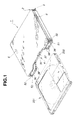
- FIGS. 1-9 show a first embodiment of the present invention wherein a sleeve-type cartridge case 1 serves to accommodate a disc cartridge 201.
- the cartridge case 1 is formed like a flat box by connecting upper and lower halves 2, 3 made of a synthetic resin.
- a pair of cartridge locking members 6 arranged on inner side faces of the cartridge compartment 5 is engaged with a pair of clamping concavities 202 arranged in side faces of the disc cartridge 201, holding the disc cartridge 201 in the cartridge compartment 5.
- the upper half 2 is formed like a square, comprising a top plate 22 having at a front end a substantially circular recess 21 which is useful when removing the disc cartridge 201, side plates 23, 24 arranged on both sides of the top plate 22, and a rear plate 25 arranged at a rear end of the top plate 22.
- the cartridge locking members 6 are integrated with the side plates 23, 24, and are formed resiliently by partly recessing the side plates 23, 24.
- the lower half 3 is formed like a square in the same way as the upper half 2, comprising a bottom plate 32 having at a front end a substantially circular recess 31 which is useful when removing the disc cartridge 201, side plates 33, 34 arranged on both sides of the bottom plate 32, and a rear plate 35 arranged at a rear end of the bottom plate 32.
- the lower half 3 is formed transparently out of a styrene or polycarbonate resin.
- the side plates 23, 24 and the rear plate 25 of the upper half 2 are arranged adjacent to the inner surfaces of the side plates 33, 34 and the rear plate 35 of the lower half 3.
- the side plates 23, 24 of the upper half 2 are formed with connecting protrusions 41, whereas the side plates 33, 34 of the lower half 3 are formed with connecting concavities 42.
- the connecting protrusions 41 and concavities 42 are engaged with each other to detachably connect the upper and lower halves 2, 3.
- An amount ( ⁇ 1 + ⁇ 1 ) of engagement depth of the connecting concavity 41 and protrusion 42 is determined to be larger than a difference ( ⁇ 2 + ⁇ 1 ) between a width W 1 of the disc cartridge 201 accommodated in the cartridge compartment 5 and a distance W 2 between the side plates 23, 24 of the upper half 2.
- an index card 301 is disposed on the bottom plate 32 of the lower half 3.
- the index card 301 has a main surface 302 disposed on stepped portions 36 arranged on both sides of the bottom plate 32 of the lower half 3, and a rear surface 303 connected substantially perpendicularly to one end of the main surface 302 and arranged adjacent to the inner surface of the rear plate 35 of the lower half 3.
- the lower half 3 has a card engaging protrusion 37 which is engaged with one end 302a of the main surface 302 of the index card 301 to prevent the index card 301 from separating from the bottom plate 32 and falling from the opening 4.
- the lower half 3 has an inclined face 38 continuously connected to the upper side of the card engaging protrusion 37, by which the disc cartridge 201 can smoothly be inserted into the cartridge compartment 5 through the opening 4. Without the inclined face 38, smooth insertion of the disc cartridge 201 cannot be obtained when contacting an end face of the card engaging protrusion 37.
- a rail-like or track-like protrusion 51 is arranged at a lower end of the outer side face of the side plate 23, 24 of the upper half 2 to extend from an end on the side of the opening 4 to the rear plate 25, whereas a rail-like or track-like concavity 52 is arranged in the inner side face of the side plate 33, 34 of the lower half 3 to extend from an end on the side of the opening 4 to the rear plate 35.
- the connecting protrusion 41 is arranged at the end of the outer side face of the side plate 23, 24 of the upper half 2 on the side of the opening 4, whereas the connecting concavity 42 is arranged at the end of the inner side face of the side plate 33, 34 of the lower half 3.
- the connecting protrusion 41 and concavity 42 are engaged with each other, obtaining the upper and lower halves 2, 3 vertically placed one upon another and engaged with each other.
- a slit-like recess 53 is arranged in the side plate 23, 24 of the upper half 2 to extend from the end on the side of the opening 4 to the connecting protrusion 41.
- the slit-like recess 53 serves to provide resiliency to the connecting protrusion 41 for easy bend thereof.
- both ends 41a, 41b of the connecting protrusion 41 are slantly formed in the slide direction to enable easy engagement/disengagement of the connecting protrusion 41 with/from the concavity 42.
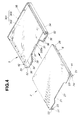
- the cartridge case I is constructed as described above. Referring to FIG. 4, upon assembling of the cartridge case 1, the rear surface 303 of the index card 301 is put on the inner surface of the rear plate 35 of the lower half 3 to place the main surface 302 of the index card 301 on the bottom plate 32 of the lower half 3. The one end 302a of the main surface 302, i.e. an opposite end to the rear surface 303, is engaged with the card engaging protrusion 37.
- the rail-like protrusions 51 arranged on the outer side faces of the side plates 23, 24 of the upper half 2 are engaged with the rail-like concavities 52 arranged in the inner side faces of the side plates 33, 34 of the lower half 3 to slide the protrusions 51 along the concavities 52.
- the cartridge locking members 6 are engaged with the clamping concavities 202 arranged on both sides of the disc cartridge 201, holding the disc cartridge 201 in the cartndge compartment 5.
- the disc cartridge 201 When rewriting or adding a description on the index card 301 or replacing the index card 301 with a new one, the disc cartridge 201 is removed from the cartndge compartment 5, then the upper and lower halves 2, 3 are slid in the direction opposite to that upon assembling. By this, the upper and lower halves 2, 3 are separated to enable easy removal of the index card 301 from the lower half 3.
- FIG. 10 shows a second embodiment of the present invention wherein a sleeve-type cartridge case 1 serves to accommodate a tape cartridge 401.
- the second embodiment is substantially the same in structure as the first embodiment except that the cartridge case 1 is formed in accordance with the size of the tape cartridge 401.
- cartridge locking members 6 are engaged with tape-end detecting holes 403 arranged on both sides of a lid 402 of the tape cartridge 401 to hold the tape cartridge 401 in a cartridge compartment 5.
- the side plates 23, 24 of the upper half 2 are arranged adjacent to the inner side faces of the side plates 33, 34 of the lower half 3.
- the side plates 23, 24 of the upper half 2 may be arranged adjacent to the outer side faces of the side plates 33, 34 of the lower half 3.
- the connecting protrusions 41 are arranged on the side plates 23, 24 of the upper half 2, whereas the connecting concavities 42 are arranged in the side plates 33, 34 of the lower half 3.
- the connecting protrusions 41 may be arranged on the lower half 3, whereas the connecting concavities 42 may be arranged in the upper half 2.
- the upper and lower halves 2, 3 may be vertically slidable for connection of the two.
Landscapes
- Packaging For Recording Disks (AREA)
- Packaging Of Annular Or Rod-Shaped Articles, Wearing Apparel, Cassettes, Or The Like (AREA)
Applications Claiming Priority (2)
| Application Number | Priority Date | Filing Date | Title |
|---|---|---|---|
| JP9205808A JPH1149271A (ja) | 1997-07-31 | 1997-07-31 | スリーブ型カートリッジ収納ケース |
| JP205808/97 | 1997-07-31 |
Publications (1)
| Publication Number | Publication Date |
|---|---|
| EP0895244A1 true EP0895244A1 (de) | 1999-02-03 |
Family
ID=16513043
Family Applications (1)
| Application Number | Title | Priority Date | Filing Date |
|---|---|---|---|
| EP98401964A Withdrawn EP0895244A1 (de) | 1997-07-31 | 1998-07-31 | Kassettenbehälter |
Country Status (7)
| Country | Link |
|---|---|
| US (1) | US6019219A (de) |
| EP (1) | EP0895244A1 (de) |
| JP (1) | JPH1149271A (de) |
| KR (1) | KR19990014306A (de) |
| CN (1) | CN1184637C (de) |
| MY (1) | MY119928A (de) |
| TW (1) | TW365594B (de) |
Families Citing this family (10)
| Publication number | Priority date | Publication date | Assignee | Title |
|---|---|---|---|---|
| DE19835287C2 (de) * | 1998-08-05 | 2000-08-31 | Behr Gmbh & Co | Gehäuse einer Heizungs- oder Klimaanlage eines Kraftfahrzeuges |
| US6876991B1 (en) | 1999-11-08 | 2005-04-05 | Collaborative Decision Platforms, Llc. | System, method and computer program product for a collaborative decision platform |
| US6332533B1 (en) | 2000-08-29 | 2001-12-25 | H.H.H. Incorprorated | Media holder mouse pad |
| WO2002061736A2 (en) | 2001-01-29 | 2002-08-08 | The Mead Corporation | Dvd sleeve |
| USD465689S1 (en) | 2001-10-22 | 2002-11-19 | Sony Corporation | Case for recording media |
| US7318529B2 (en) | 2003-09-19 | 2008-01-15 | Vest Medical, Llc | Method for sorting discarded and spent pharmaceutical items |
| GB2420846B (en) * | 2004-12-04 | 2009-07-08 | Ford Global Technologies Llc | A cooling system for a motor vehicle engine |
| JP2006306417A (ja) * | 2005-04-27 | 2006-11-09 | Tdk Corp | 情報記録媒体 |
| JP2007184473A (ja) * | 2006-01-10 | 2007-07-19 | Funai Electric Co Ltd | 電気機器キャビネット |
| WO2011030176A1 (en) * | 2009-09-09 | 2011-03-17 | Sandisk Il Ltd. | Holders for portable memory cards and method for manufacturing same |
Citations (3)
| Publication number | Priority date | Publication date | Assignee | Title |
|---|---|---|---|---|
| US4838422A (en) * | 1987-11-23 | 1989-06-13 | Empak, Inc. | Data storage container |
| EP0564155A2 (de) * | 1992-03-31 | 1993-10-06 | Sony Corporation | Behälter für die Aufbewahrung einer Plattenkassette und Verpackungsverfahren eines solchen Behälters |
| GB2268473A (en) * | 1992-07-06 | 1994-01-12 | Tdk Corp | Casing e.g.for housing a cartridge |
-
1997
- 1997-07-31 JP JP9205808A patent/JPH1149271A/ja not_active Withdrawn
-
1998
- 1998-07-20 MY MYPI98003305A patent/MY119928A/en unknown
- 1998-07-23 TW TW087112049A patent/TW365594B/zh active
- 1998-07-28 US US09/123,514 patent/US6019219A/en not_active Expired - Fee Related
- 1998-07-30 KR KR1019980030866A patent/KR19990014306A/ko not_active Ceased
- 1998-07-31 EP EP98401964A patent/EP0895244A1/de not_active Withdrawn
- 1998-07-31 CN CNB981172784A patent/CN1184637C/zh not_active Expired - Fee Related
Patent Citations (3)
| Publication number | Priority date | Publication date | Assignee | Title |
|---|---|---|---|---|
| US4838422A (en) * | 1987-11-23 | 1989-06-13 | Empak, Inc. | Data storage container |
| EP0564155A2 (de) * | 1992-03-31 | 1993-10-06 | Sony Corporation | Behälter für die Aufbewahrung einer Plattenkassette und Verpackungsverfahren eines solchen Behälters |
| GB2268473A (en) * | 1992-07-06 | 1994-01-12 | Tdk Corp | Casing e.g.for housing a cartridge |
Also Published As
| Publication number | Publication date |
|---|---|
| CN1207555A (zh) | 1999-02-10 |
| US6019219A (en) | 2000-02-01 |
| CN1184637C (zh) | 2005-01-12 |
| TW365594B (en) | 1999-08-01 |
| JPH1149271A (ja) | 1999-02-23 |
| KR19990014306A (ko) | 1999-02-25 |
| MY119928A (en) | 2005-08-30 |
Similar Documents
| Publication | Publication Date | Title |
|---|---|---|
| KR100275350B1 (ko) | 디스크 카트리지용 케이스 및 디스크 카트리지를 홀딩하기 위한 홀드 부재 | |
| US6019219A (en) | Sleeve-type cartridge cases | |
| KR100558721B1 (ko) | 디스크 형태의 정보매체용 하우징 | |
| US4287989A (en) | Storage container for magnetic tape cassettes | |
| EP0549360A2 (de) | Aufnahmekassette für einen scheibenförmigen Aufzeichnungsträger | |
| KR19990072481A (ko) | 디스크카트리지의수납케이스 | |
| KR910008943Y1 (ko) | 마그네틱 테이프 카세트용 보관용기 | |
| US20060180486A1 (en) | Modular panel and storage system for flat items such as media discs and holders therefor | |
| KR19990088336A (ko) | 디스크카트리지를수납하기위한케이스 | |
| JP3106679B2 (ja) | ディスクカートリッジ用ケース | |
| JP2001344924A (ja) | スリーブ型カートリッジ収納ケース | |
| EP0632454A1 (de) | Behälter für Plattenkassette | |
| KR200347362Y1 (ko) | 메탈 cd 케이스 | |
| JP3692152B2 (ja) | ディスクカートリッジの収納ケース | |
| JP3601741B2 (ja) | カートリッジ収納ケース | |
| US7377386B2 (en) | Mechanical attachment for packaging | |
| KR100757051B1 (ko) | 광기록매체 케이스 | |
| KR200334209Y1 (ko) | Cd 케이스 | |
| JPH06247486A (ja) | 記録ディスク収納ケース | |
| JP3024422U (ja) | ミニディスク保管用ケース | |
| JPH0643028Y2 (ja) | コンパクトディスクケース保持具 | |
| KR200239925Y1 (ko) | 미니 컴팩트 디스크 수납 케이스 | |
| KR100555937B1 (ko) | 홀로그래픽 디지털 데이터 저장 시스템용 저장 매체 구조 | |
| KR100268589B1 (ko) | 디스크 카트리지 | |
| JPH06247485A (ja) | 記録ディスク収納ケース |
Legal Events
| Date | Code | Title | Description |
|---|---|---|---|
| PUAI | Public reference made under article 153(3) epc to a published international application that has entered the european phase |
Free format text: ORIGINAL CODE: 0009012 |
|
| AK | Designated contracting states |
Kind code of ref document: A1 Designated state(s): AT DE FR GB NL |
|
| AX | Request for extension of the european patent |
Free format text: AL;LT;LV;MK;RO;SI |
|
| 17P | Request for examination filed |
Effective date: 19990727 |
|
| AKX | Designation fees paid |
Free format text: AT DE FR GB NL |
|
| GRAP | Despatch of communication of intention to grant a patent |
Free format text: ORIGINAL CODE: EPIDOSNIGR1 |
|
| STAA | Information on the status of an ep patent application or granted ep patent |
Free format text: STATUS: THE APPLICATION IS DEEMED TO BE WITHDRAWN |
|
| 18D | Application deemed to be withdrawn |
Effective date: 20050419 |