EP0899505A2 - Combined power generation plant - Google Patents
Combined power generation plant Download PDFInfo
- Publication number
- EP0899505A2 EP0899505A2 EP98110981A EP98110981A EP0899505A2 EP 0899505 A2 EP0899505 A2 EP 0899505A2 EP 98110981 A EP98110981 A EP 98110981A EP 98110981 A EP98110981 A EP 98110981A EP 0899505 A2 EP0899505 A2 EP 0899505A2
- Authority
- EP
- European Patent Office
- Prior art keywords
- exhaust gas
- power generation
- generation plant
- combined power
- combustion catalysis
- Prior art date
- Legal status (The legal status is an assumption and is not a legal conclusion. Google has not performed a legal analysis and makes no representation as to the accuracy of the status listed.)
- Granted
Links
- 238000010248 power generation Methods 0.000 title claims abstract description 53
- 238000002485 combustion reaction Methods 0.000 claims abstract description 63
- 238000006555 catalytic reaction Methods 0.000 claims abstract description 54
- 239000000446 fuel Substances 0.000 claims abstract description 17
- 239000003054 catalyst Substances 0.000 claims description 40
- 230000001105 regulatory effect Effects 0.000 claims description 5
- 229910052723 transition metal Inorganic materials 0.000 claims description 4
- 150000003624 transition metals Chemical class 0.000 claims description 4
- 239000007789 gas Substances 0.000 description 104
- 241000196324 Embryophyta Species 0.000 description 35
- 239000002918 waste heat Substances 0.000 description 22
- VNWKTOKETHGBQD-UHFFFAOYSA-N methane Chemical compound C VNWKTOKETHGBQD-UHFFFAOYSA-N 0.000 description 20
- 238000011084 recovery Methods 0.000 description 17
- QGZKDVFQNNGYKY-UHFFFAOYSA-N Ammonia Chemical compound N QGZKDVFQNNGYKY-UHFFFAOYSA-N 0.000 description 12
- ATUOYWHBWRKTHZ-UHFFFAOYSA-N Propane Chemical compound CCC ATUOYWHBWRKTHZ-UHFFFAOYSA-N 0.000 description 12
- XLYOFNOQVPJJNP-UHFFFAOYSA-N water Substances O XLYOFNOQVPJJNP-UHFFFAOYSA-N 0.000 description 9
- PNEYBMLMFCGWSK-UHFFFAOYSA-N aluminium oxide Inorganic materials [O-2].[O-2].[O-2].[Al+3].[Al+3] PNEYBMLMFCGWSK-UHFFFAOYSA-N 0.000 description 8
- 229910021529 ammonia Inorganic materials 0.000 description 6
- 229910052593 corundum Inorganic materials 0.000 description 6
- BASFCYQUMIYNBI-UHFFFAOYSA-N platinum Chemical group [Pt] BASFCYQUMIYNBI-UHFFFAOYSA-N 0.000 description 6
- 239000001294 propane Substances 0.000 description 6
- 229910001845 yogo sapphire Inorganic materials 0.000 description 6
- 239000000463 material Substances 0.000 description 4
- 229910052751 metal Inorganic materials 0.000 description 4
- 239000002184 metal Substances 0.000 description 4
- XEEYBQQBJWHFJM-UHFFFAOYSA-N Iron Chemical group [Fe] XEEYBQQBJWHFJM-UHFFFAOYSA-N 0.000 description 3
- 238000006243 chemical reaction Methods 0.000 description 3
- 238000002347 injection Methods 0.000 description 3
- 239000007924 injection Substances 0.000 description 3
- 238000000034 method Methods 0.000 description 3
- PXHVJJICTQNCMI-UHFFFAOYSA-N Nickel Chemical compound [Ni] PXHVJJICTQNCMI-UHFFFAOYSA-N 0.000 description 2
- KDLHZDBZIXYQEI-UHFFFAOYSA-N Palladium Chemical compound [Pd] KDLHZDBZIXYQEI-UHFFFAOYSA-N 0.000 description 2
- VYPSYNLAJGMNEJ-UHFFFAOYSA-N Silicium dioxide Chemical compound O=[Si]=O VYPSYNLAJGMNEJ-UHFFFAOYSA-N 0.000 description 2
- GWEVSGVZZGPLCZ-UHFFFAOYSA-N Titan oxide Chemical compound O=[Ti]=O GWEVSGVZZGPLCZ-UHFFFAOYSA-N 0.000 description 2
- MCMNRKCIXSYSNV-UHFFFAOYSA-N Zirconium dioxide Chemical compound O=[Zr]=O MCMNRKCIXSYSNV-UHFFFAOYSA-N 0.000 description 2
- 239000002585 base Substances 0.000 description 2
- 230000006835 compression Effects 0.000 description 2
- 238000007906 compression Methods 0.000 description 2
- 229910052802 copper Inorganic materials 0.000 description 2
- 239000010949 copper Substances 0.000 description 2
- 229910052878 cordierite Inorganic materials 0.000 description 2
- JSKIRARMQDRGJZ-UHFFFAOYSA-N dimagnesium dioxido-bis[(1-oxido-3-oxo-2,4,6,8,9-pentaoxa-1,3-disila-5,7-dialuminabicyclo[3.3.1]nonan-7-yl)oxy]silane Chemical compound [Mg++].[Mg++].[O-][Si]([O-])(O[Al]1O[Al]2O[Si](=O)O[Si]([O-])(O1)O2)O[Al]1O[Al]2O[Si](=O)O[Si]([O-])(O1)O2 JSKIRARMQDRGJZ-UHFFFAOYSA-N 0.000 description 2
- 150000002739 metals Chemical class 0.000 description 2
- 239000003345 natural gas Substances 0.000 description 2
- 229910052697 platinum Inorganic materials 0.000 description 2
- 239000000843 powder Substances 0.000 description 2
- 239000002994 raw material Substances 0.000 description 2
- 230000009467 reduction Effects 0.000 description 2
- MHOVAHRLVXNVSD-UHFFFAOYSA-N rhodium atom Chemical compound [Rh] MHOVAHRLVXNVSD-UHFFFAOYSA-N 0.000 description 2
- 101100385565 Arabidopsis thaliana CTF7 gene Proteins 0.000 description 1
- VYZAMTAEIAYCRO-UHFFFAOYSA-N Chromium Chemical compound [Cr] VYZAMTAEIAYCRO-UHFFFAOYSA-N 0.000 description 1
- RYGMFSIKBFXOCR-UHFFFAOYSA-N Copper Chemical compound [Cu] RYGMFSIKBFXOCR-UHFFFAOYSA-N 0.000 description 1
- 101150010030 ECO1 gene Proteins 0.000 description 1
- 239000003513 alkali Substances 0.000 description 1
- 238000007084 catalytic combustion reaction Methods 0.000 description 1
- 229910052804 chromium Inorganic materials 0.000 description 1
- 239000011651 chromium Substances 0.000 description 1
- 239000003426 co-catalyst Substances 0.000 description 1
- 238000010276 construction Methods 0.000 description 1
- 230000001276 controlling effect Effects 0.000 description 1
- 239000013256 coordination polymer Substances 0.000 description 1
- 230000003247 decreasing effect Effects 0.000 description 1
- HNPSIPDUKPIQMN-UHFFFAOYSA-N dioxosilane;oxo(oxoalumanyloxy)alumane Chemical compound O=[Si]=O.O=[Al]O[Al]=O HNPSIPDUKPIQMN-UHFFFAOYSA-N 0.000 description 1
- 230000000694 effects Effects 0.000 description 1
- 238000011156 evaluation Methods 0.000 description 1
- 230000006872 improvement Effects 0.000 description 1
- 229910052742 iron Inorganic materials 0.000 description 1
- GEYXPJBPASPPLI-UHFFFAOYSA-N manganese(III) oxide Inorganic materials O=[Mn]O[Mn]=O GEYXPJBPASPPLI-UHFFFAOYSA-N 0.000 description 1
- 229910052759 nickel Inorganic materials 0.000 description 1
- 150000002894 organic compounds Chemical class 0.000 description 1
- 229910052763 palladium Inorganic materials 0.000 description 1
- 238000000746 purification Methods 0.000 description 1
- 229910052761 rare earth metal Inorganic materials 0.000 description 1
- 229910052703 rhodium Inorganic materials 0.000 description 1
- 239000010948 rhodium Substances 0.000 description 1
- 239000000377 silicon dioxide Substances 0.000 description 1
- 229910052720 vanadium Inorganic materials 0.000 description 1
- LEONUFNNVUYDNQ-UHFFFAOYSA-N vanadium atom Chemical compound [V] LEONUFNNVUYDNQ-UHFFFAOYSA-N 0.000 description 1
Images


Classifications
-
- F—MECHANICAL ENGINEERING; LIGHTING; HEATING; WEAPONS; BLASTING
- F22—STEAM GENERATION
- F22B—METHODS OF STEAM GENERATION; STEAM BOILERS
- F22B1/00—Methods of steam generation characterised by form of heating method
- F22B1/02—Methods of steam generation characterised by form of heating method by exploitation of the heat content of hot heat carriers
- F22B1/18—Methods of steam generation characterised by form of heating method by exploitation of the heat content of hot heat carriers the heat carrier being a hot gas, e.g. waste gas such as exhaust gas of internal-combustion engines
- F22B1/1807—Methods of steam generation characterised by form of heating method by exploitation of the heat content of hot heat carriers the heat carrier being a hot gas, e.g. waste gas such as exhaust gas of internal-combustion engines using the exhaust gases of combustion engines
- F22B1/1815—Methods of steam generation characterised by form of heating method by exploitation of the heat content of hot heat carriers the heat carrier being a hot gas, e.g. waste gas such as exhaust gas of internal-combustion engines using the exhaust gases of combustion engines using the exhaust gases of gas-turbines
-
- Y—GENERAL TAGGING OF NEW TECHNOLOGICAL DEVELOPMENTS; GENERAL TAGGING OF CROSS-SECTIONAL TECHNOLOGIES SPANNING OVER SEVERAL SECTIONS OF THE IPC; TECHNICAL SUBJECTS COVERED BY FORMER USPC CROSS-REFERENCE ART COLLECTIONS [XRACs] AND DIGESTS
- Y02—TECHNOLOGIES OR APPLICATIONS FOR MITIGATION OR ADAPTATION AGAINST CLIMATE CHANGE
- Y02T—CLIMATE CHANGE MITIGATION TECHNOLOGIES RELATED TO TRANSPORTATION
- Y02T10/00—Road transport of goods or passengers
- Y02T10/10—Internal combustion engine [ICE] based vehicles
- Y02T10/12—Improving ICE efficiencies
Definitions
- the present invention relates to a combined power generation plant.
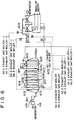
- FIG. 6 shows one example of a well-known multi-shaft reheat type combined power generation plant.
- This plant includes gas turbines 601, exhaust gas boilers 602, a steam turbine 603, and generators. Although three gas turbines 601 and three exhaust gas boilers are provided, only one each is shown, and No. 2 and No. 3 gas turbines and exhaust gas boilers are omitted in the figure.
- the gas turbine 601 takes in air from the compression side, feeds burned fuel to the expansion side, and sends exhaust gas to the exhaust gas boiler 602. This gas turbine 601 generates electric power.
- the exhaust gas boiler 602 uses a triple pressure reheat type construction having low-, intermediate-, and high-pressure waste heat recovery sections.
- this exhaust gas boiler includes a low-pressure economizer (LF ECO) 604, a low-pressure evaporator (LP EVA) 605, a high-and intermediate-pressure economizer (IF ECO & HP ECO1) 606, an intermediate-pressure evaporator (IF EVA) 607, a low-pressure superheater (LP SH) 608, an intermediate-pressure superheater (IF SP) 609, a high-pressure economizer (HF ECO2) 610, a high-pressure evaporator (HP EVA) 611, a high-pressure superheater (HP SH) 612, and a reheater (IP RH) 613.
- the operations of these pieces of the aforesaid equipment are the same as those of the publicly known equipment.
- an NOx removal system 614 is provided at the subsequent stage of the high-pressure evapor
- BFP stands for a boiler feed water pump.
- CP stands for a condensed water pump.
- GC stands for a grand condenser heater.
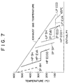
- FIG. 7 shows a sequence for waste heat recovery in the aforesaid waste heat recovery equipment.
- the abbreviation indicated by alphabets corresponds to each of the aforesaid waste heat recovery equipment.
- the exhaust gas boiler 602 recovers waste heat from the exhaust gas introduced from the inlet by using the aforesaid equipment, and feeds the generated steam to the steam turbine 603 to generate electric power.
- the exhaust gas is finally discharged through a stack.
- the solid lines indicate the flow of feed water
- the dotted lines indicate the flow of steam.
- steam is sent from not only the shown No. 1 exhaust gas boiler 602 but also No. 2 and No.3 exhaust gas boilers. Also, water from a condenser and make-up water are sent to these exhaust boilers through lines.
- exhaust gas boiler 602 is of a triple pressure reheat type having low-, intermediate-, and high-pressure waste heat recovery sections is that as seen from FIG. 7, waste heat cannot be recovered well at low temperatures by the high-pressure waste heat recovery section (HP ECO, HP EVA, HP SH) only.
- an object of the present invention is to provide a combined power generation plant which increases the power generation efficiency by raising the temperature of exhaust gas without combustion due to fuel ignition in an exhaust gas boiler.
- one aspect of the present invention is a combined power generation plant in which electric power is generated by a power generation gas turbine, exhaust gas from the power generation gas turbine is sent to an exhaust gas boiler, and a power generation steam turbine is rotated with the steam generated by heat recovered by the exhaust gas boiler to generate electric power
- the improvement resides in that the exhaust gas boiler consists of a high-pressure reheat type steam system in which fuel is supplied to the exhaust gas boiler, and the supplied fuel undergoes catalytic reaction in a combustion catalysis section to increase the temperature of exhaust gas, whereby the power generation efficiency is improved.
- the combustion catalysis section can be provided at the preceding stage of either one or both of a reheater and a superheater. Further, the combustion catalysis section can be provided at the preceding stage of at least any one of a reheater, a re-reheater, and a superheater.
- a catalyst used in the combustion catalysis section can be a catalyst containing a transition metal or an oxide thereof. Any of the combustion catalysis sections may have an NOx removal performance.
- the exhaust gas boiler may be provided with a temperature sensor
- an LNG supply system may be provided with a flow control and a flow regulating valve, and the flow regulating valve may be controlled by the flow control to control the supply amount of LNG, whereby the temperature of exhaust gas can be kept proper.
- a combined power generation plant which increases the power generation efficiency by raising the temperature of exhaust gas without combustion due to fuel ignition in an exhaust gas boiler.
- an automotive exhaust gas combustion catalyst whose performance has already been verified practically as described above, can be used.
- Such a catalyst in a small amount is expected to achieve a sufficient effect, so that too large an apparatus is not needed.
- unburned combustibles of LNG in the exhaust gas from the gas turbine can be burned completely.
- the temperature control of exhaust gas can be carried out relatively easily by controlling the quantity of LNG supplied to the exhaust gas boiler. Therefore, in designing the pipes in which steam circulates, excessive material quality and wall thickness need not be set.
- FIG. 1 shows one embodiment of a combined power generation plant in accordance with the present invention.
- This embodiment relates to a multi-shaft reheat type combined plant in which a gas turbine 1, exhaust gas boiler (waste heat recovery boiler) 2, and a steam turbine 3 are combined.
- a gas turbine 1 and only one exhaust gas boiler 2 are shown in the figure, a plurality of these pieces of equipment may be provided in parallel as in the above-described conventional example.
- the gas turbine 1 takes in air from the compression side 4, burns fuel (LNG gas) in a combustion chamber 6 and feeds it to the expansion side 5, and sends exhaust gas to an exhaust gas boiler 2.
- the rotation of this gas turbine 1 generates electric power by using a generator 7.
- the steam system of the exhaust gas boiler 2 is of a high-pressure reheat type.
- feed water flows through a high-pressure economizer (HP ECO) 8, a high-pressure evaporator (HP EVA) 9, and a high-pressure superheater (HP SH) 10 to recover waste heat.
- HP ECO high-pressure economizer
- HP EVA high-pressure evaporator
- HP SH high-pressure superheater
- the steam from the high-pressure superheater 10 is supplied to the high pressure side (HP) 11 of the steam turbine 3, returned to a reheater (RH) 12, and then supplied to the intermediate pressure side (IP) 13 of the steam turbine. Then, the steam is sent from the intermediate pressure side to the low pressure side (LP) 14, being returned to water by a condenser 15, and fed to the exhaust gas boiler 2 through a compressor 16 as feed water. Although not shown, make-up water is appropriately supplied separately.
- the steam turbine 3 is rotated, so that electric power is generated by using a generator 17.
- the exhaust gas from the exhaust gas boiler 3 is finally discharged through a stack 21.
- the exhaust gas boiler 2 includes combustion catalysis sections 18 and 19, which are the characteristic portions of the present invention, and a fuel supply line 20.
- the combustion catalysis sections 18 and 19 are provided at the preceding stage of the reheater 12 and the high-pressure superheater 10 as shown in the figure.
- a fuel injection system for supplying fuel from the fuel (LNG gas) supply line 20 is provided.
- a catalyst containing a transition metal or its oxide preferably, a catalyst containing a metal of iron group element and/or platinum group element or its oxide can be enumerated.
- the following catalyst can be used.
- the quantity of catalyst used in the combustion catalysis sections 18 and 19 should be sufficient for at least the assumed gas flow rate and the intended exhaust gas temperature.
- the combustion caused by catalytic reaction is not a combustion reaction such that the fire flames up, unlike the combustion reaction caused by ordinary ignition. Therefore, the control is relatively easy.
- temperature sensors 22, 23, 24, and 25 are provided at appropriate positions, and flow regulating valves 28 and 29 are appropriately controlled by flow controls 26 and 27 to control the supply of LNG, by which the temperature is kept proper.
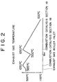
- FIG. 2 shows the distribution of exhaust gas temperature.
- the exhaust gas temperature of 585°C at the exhaust gas boiler inlet is changed to 650°C after the gas passes through the combustion catalysis section 18, decreased to 550°C after the gas passes through the reheater 12, and changed again to 650°C after the gas passes through the combustion catalysis section 19.
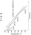
- FIG. 3 shows a thermodynamic sequence of waste heat recovery according to this embodiment.
- the abbreviation indicated by alphabets corresponds to each of the aforesaid waste heat recovery equipment.
- the thermal efficiency of the exhaust gas boiler 2 is increased.
- waste heat recovery is carried out like the high-pressure economizer (HP ECO), high-pressure evaporator (HP EVA), and high-pressure superheater (HP SH) indicated by the thick solid line and the reheater (RH) indicated by the dotted line.
- HP ECO high-pressure economizer
- HP EVA high-pressure evaporator
- HP SH high-pressure superheater
- RH reheater
- This embodiment has the same configuration as that of the above embodiment described with reference to FIG. 1, except that the aforesaid combustion catalysis sections 18 and 19 are also used as NOx removal sections.
- a catalyst having not only a function of combustion catalyst but also a function of NOx removal catalyst is used.
- catalysts having both of the functions of combustion catalyst and NOx removal catalyst various catalysts can be used.
- catalysts in which an active metal such as Ga, Pd, Cu, and Co is supported on a carrier such as ZSM-5 type zeolite, mordenite, and Al 2 O 3 can be enumerated.
- Co-Beta, Co-Mor, Co-ZSM-5, and Co/Al 2 O 3 are preferable, which are listed in Table 1 in "Takeshi Tabata, Takatoshi Nakahira, and Hirofumi Ohtsuka, NOx Selecting Reduction Catalyst for Natural Gas Combustion Exhaust Gas Purification, Catalysts & Catalysis (issued by Catalysis Society of Japan) Vol. 39, No. 3, 1997".
- the Co-Beta catalyst which is one kind of Co-ZSM-5 catalyst, is ideal.
- This catalyst decomposes 100% of LNG component at 500°C, and at the same time decomposes NOx component with high efficiency.
- This catalyst also has an enhanced life.
- Pt/Al 2 O 3 , Rh/Al 2 O 3 , Ag/Al 2 O 3 , Co/Al 2 O 3 , AuMn/Al 2 O 3 , Pt-ZSM-5, Cu-ZSM-5, Ir/In-ZSM-5, and Mn 2 O 3 /Ce-ZSM-5 can also be used, which are listed in Table 1 in "Akira Obuchi, Isamu Kaneko, Junko Ohi, Akihiko Ohi, Atushi Ogata, Satoshi Kushiyama, and koichi Mizuno, Evaluation of NOx Selecting Reduction Catalyst Using Organic Compound with Diesel Exhaust Gas Actual Scale, Catalysts & Catalysis (issued by Catalysis Society of Japan) Vol. 38, No. 2, 1996".
- the concentration of NOx component is usually 30 to 50 ppm (O 2 16% conversion) at the exhaust gas boiler inlet. This concentration must be kept at a value of 5 ppm or less at the exhaust gas boiler outlet.
- a concentration of about 2000 ppm (O 2 16% conversion) is added. Therefore, of this concentration, 50 ppm (O 2 16% conversion) at the most is consumed in NOx removal. For this reason, the combustion catalysis section can have an NOx removal performance without hindrance.
- propane is the most efficient. Therefore, standard LNG from Indonesia, Malaysia, and Australia containing propane of about 1/40 (molar ratio) is preferable. For LNG containing less propane, propane may be added so that the LNG contains propane of about 1/40 (molar ratio). Further, only propane can be supplied.
- LNG in the combustion catalysis sections 18 and 19, LNG can be burned, and also NOx can be removed efficiently.
- This embodiment has advantages over the case of ammonia injection that a high-pressure ammonia supply facility (tank, etc.) is not needed, the leakage of ammonia need not be considered, and only an LNG facility is necessary.
- the combined power generation plant in accordance with the present invention is not limited to the above-described embodiments, and can be modified variously in the scope of technical conception of the present invention.
- the combustion catalysis section (NOx removal section) 18, 19 may be provided at the preceding stage of either one of the reheater and superheater.
- the combustion catalysis section can be provided at the preceding stage of at least any one of the reheater, re-reheater, and superheater.
- combustion catalysis sections Although all combustion catalysis sections have NOx removal performance in the above-described embodiment (No. 2), at least one combustion catalysis section may have NOx removal performance. Further, in the above-described embodiment (No. 2), a combustion catalyst having NOx removal performance is used. However, both of a combustion catalyst and an NOx removal catalyst are used so as to give NOx removal performance to the combustion catalysis section. Still further, the NOx removal performance can be given to the combustion catalysis section by providing two-layer combustion catalysis section consisting of a combustion catalyst layer and an NOx removal catalyst layer.
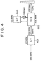
- FIGS. 4 and 5 are schematic views for clarifying the calculation procedure.
- FIG. 4 relates to a combined power generation plant in operation at present.
- Raw material LNG gas corresponding to 658.9 MW is introduced to the gas turbine 601, where electric power of 226 MW is generated, and exhaust gas of 585°C corresponding to 432.9 MW is discharged.
- This gas turbine 601 uses a 1500°C-class gas turbine which has a higher efficiency than the aforesaid conventional 1350°C-class gas turbine.
- the exhaust gas is sent to the aforesaid conventional triple pressure reheat type exhaust gas boiler 602, and receives heat corresponding to 306.4 MW by waste heat recovery. This heat generates electric power of 103.5 MW by using the steam turbine 603. Of the received energy, the energy corresponding to 200.8 MW is discharged by the condenser, and 2.1 MW is lost by mechanical loss. Exhaust gas of 100°C is discharged from the exhaust gas boiler 602, and the energy corresponding to 126.5 MW is also discharged.
- FIG. 5 relates to a combined power generation plant of the above-described embodiment shown in FIG. 1.
- Raw material LNG gas corresponding to 658.9 MW is introduced to the gas turbine 1, where electric power of 226 MW is generated, and exhaust gas of 585°C corresponding to 432.9 MW is discharged.
- This gas turbine 1 uses a 1500°C-class gas turbine.
- the exhaust gas is sent to the exhaust gas boiler 2 of the embodiment shown in FIG. 1, supplied with LNG gas corresponding to 81.7 MW, and receives heat corresponding to 379.9 MW by waste heat recovery. This heat generates electric power of 169.4 MW by using the steam turbine 3. Of the received energy, the energy corresponding to 207.1 MW is consumed by the condenser 15, and 3.4 MW is lost by mechanical loss. Exhaust gas is discharged from the exhaust gas boiler 2, and the energy corresponding to 134.7 MW is also discharged.
- a combustion catalysis test was made for the purpose of utilization for gas turbine vehicles using methane of natural gas component.
- a catalyst in which a heat-resistant base material of cordierite is coated with powder in which platinum is supported as an active component on an alumina carrier was used.
- the test was made under the conditions that the methane concentration in the inlet gas is 1.85%, the GHSV(Gas Hourly Space Velocity) is 2 x 10 4 to 6 x 10 4 h -1 , and test temperature is 350 to 450°C.
- the test result is given in Table 1. Methane combustion test result GHSV (h -1 ) 350°C 400°C 450°C Methane conc. (ppm) Combustion rate (%) Methane conc.
Landscapes
- Engineering & Computer Science (AREA)
- Chemical & Material Sciences (AREA)
- Combustion & Propulsion (AREA)
- Life Sciences & Earth Sciences (AREA)
- Sustainable Development (AREA)
- Sustainable Energy (AREA)
- Physics & Mathematics (AREA)
- Thermal Sciences (AREA)
- Mechanical Engineering (AREA)
- General Engineering & Computer Science (AREA)
- Engine Equipment That Uses Special Cycles (AREA)
- Control Of Steam Boilers And Waste-Gas Boilers (AREA)
Abstract
Description
| Methane combustion test result | ||||||
| GHSV (h-1) | 350°C | 400°C | 450°C | |||
| Methane conc. (ppm) | Combustion rate (%) | Methane conc. (ppm) | Combustion rate (%) | Methane conc. (ppm) | Combustion rate (%) | |
| 2×10⁴ | 0.6 | 99.9968 | 0.2 | 99.9989 | 0.1 | 99.9995 |
| 4×10⁴ | 2.50 | 99.9865 | 1.54 | 99.9917 | 0.76 | 99.9959 |
| 6×10⁴ | 27.2 | 99.8530 | 20.2 | 99.8908 | 15.2 | 99.9178 |
Claims (10)
- A combined power generation plant in which electric power is generated by a power generation gas turbine, exhaust gas from said power generation gas turbine is sent to an exhaust gas boiler, and a power generation steam turbine is rotated with the steam generated by heat recovered by said exhaust gas boiler to generate electric power, characterized in that said exhaust gas boiler consists of a high-pressure reheat type steam system in which fuel is supplied to said exhaust gas boiler, and the supplied fuel undergoes catalytic reaction in a combustion catalysis section to increase the temperature of exhaust gas, whereby the power generation efficiency is improved.
- A combined power generation plant according to claim 1, wherein said combustion catalysis section is provided at the preceding stage of either one or both of a reheater and a superheater.
- A combined power generation plant according to claim 1, wherein said combustion catalysis section is provided at the preceding stage of at least any one of a reheater, a re-reheater, and a superheater.
- A combined power generation plant according to any one of claims 1 to 3, wherein a catalyst used in said combustion catalysis section is a catalyst containing a transition metal or an oxide thereof.
- A combined power generation plant according to any one of claims 1 to 3, wherein at least one of said combustion catalysis sections has an NOx removal performance.
- A combined power generation plant in which electric power is generated by a power generation gas turbine, exhaust gas from said power generation gas turbine is sent to an exhaust gas boiler, and a power generation steam turbine is rotated with the steam generated by heat recovered by said exhaust gas boiler to generate electric power, characterized in that said exhaust gas boiler consists of a high-pressure reheat type steam system in which fuel is supplied to said exhaust gas boiler, and the supplied fuel undergoes catalytic reaction in a combustion catalysis section to increase the temperature of exhaust gas, wherein said exhaust gas boiler is provided with a temperature sensor, an LNG supply system is provided with a flow control and a flow regulating valve, and said flow regulating valve is controlled by said flow control to control the supply amount of LNG, whereby the temperature of exhaust gas is kept proper.
- A combined power generation plant according to claim 6, wherein said combustion catalysis section is provided at the preceding stage of either one or both of a reheater and a superheater.
- A combined power generation plant according to claim 6, wherein said combustion catalysis section is provided at the preceding stage of at least any one of a reheater, a re-reheater, and a superheater.
- A combined power generation plant according to any one of claims 6 to 8, wherein a catalyst used in said combustion catalysis section is a catalyst containing a transition metal or an oxide thereof.
- A combined power generation plant according to any one of claims 6 to 8, wherein at least one of said combustion catalysis sections has an NOx removal performance.
Applications Claiming Priority (6)
| Application Number | Priority Date | Filing Date | Title |
|---|---|---|---|
| JP23378597 | 1997-08-29 | ||
| JP23378597 | 1997-08-29 | ||
| JP233785/97 | 1997-08-29 | ||
| JP254970/97 | 1997-09-19 | ||
| JP25497097 | 1997-09-19 | ||
| JP25497097A JP3794796B2 (en) | 1997-08-29 | 1997-09-19 | Combined power plant |
Publications (3)
| Publication Number | Publication Date |
|---|---|
| EP0899505A2 true EP0899505A2 (en) | 1999-03-03 |
| EP0899505A3 EP0899505A3 (en) | 2001-10-04 |
| EP0899505B1 EP0899505B1 (en) | 2005-03-09 |
Family
ID=26531202
Family Applications (1)
| Application Number | Title | Priority Date | Filing Date |
|---|---|---|---|
| EP98110981A Expired - Lifetime EP0899505B1 (en) | 1997-08-29 | 1998-06-16 | Combined power generation plant |
Country Status (8)
| Country | Link |
|---|---|
| US (1) | US6141956A (en) |
| EP (1) | EP0899505B1 (en) |
| JP (1) | JP3794796B2 (en) |
| CN (1) | CN1167894C (en) |
| CA (1) | CA2240919C (en) |
| DE (1) | DE69829250T2 (en) |
| ID (1) | ID20892A (en) |
| MY (1) | MY116749A (en) |
Cited By (6)
| Publication number | Priority date | Publication date | Assignee | Title |
|---|---|---|---|---|
| WO2007090692A3 (en) * | 2006-02-06 | 2008-01-10 | Siemens Ag | Waste heat steam generator with pore burners |
| WO2008107916A1 (en) * | 2007-03-02 | 2008-09-12 | Ansaldo Energia S.P.A. | Combined cycle electric power plant and relating operating method |
| EP2199547A1 (en) * | 2008-12-19 | 2010-06-23 | Siemens Aktiengesellschaft | Heat steam producer and method for improved operation of same |
| FR2966905A1 (en) * | 2010-10-29 | 2012-05-04 | Gen Electric | HEAT RECOVERY VAPOR GENERATOR WITH NOX REDUCTION |
| EP2647802A1 (en) * | 2012-04-04 | 2013-10-09 | Siemens Aktiengesellschaft | Power plant and method for operating a power plant assembly |
| WO2023057191A1 (en) * | 2021-10-05 | 2023-04-13 | Umicore Ag & Co. Kg | A combustion turbine and heat recovery system combination with scr reactor assembly, and methods of assembling and using the same |
Families Citing this family (19)
| Publication number | Priority date | Publication date | Assignee | Title |
|---|---|---|---|---|
| DE19829088C2 (en) * | 1998-06-30 | 2002-12-05 | Man Turbomasch Ag Ghh Borsig | Electricity generation in a composite power plant with a gas and a steam turbine |
| DE10228335B3 (en) * | 2002-06-25 | 2004-02-12 | Siemens Ag | Heat recovery steam generator with auxiliary steam generation |
| JP3702267B2 (en) * | 2002-11-13 | 2005-10-05 | 三菱重工業株式会社 | Single-shaft combined cycle plant |
| US7272932B2 (en) * | 2002-12-09 | 2007-09-25 | Dresser, Inc. | System and method of use of expansion engine to increase overall fuel efficiency |
| US8181463B2 (en) * | 2005-10-31 | 2012-05-22 | Ormat Technologies Inc. | Direct heating organic Rankine cycle |
| CA2659278A1 (en) * | 2006-07-28 | 2008-01-31 | William S. Rollins Iii | High efficiency integrated gasification combined cycle power plant |
| US20080145805A1 (en) * | 2006-12-14 | 2008-06-19 | Towler Gavin P | Process of Using a Fired Heater |
| US8220274B2 (en) * | 2008-05-15 | 2012-07-17 | Johnson Matthey Inc. | Emission reduction method for use with a heat recovery steam generation system |
| JP5148426B2 (en) * | 2008-09-17 | 2013-02-20 | 三菱重工業株式会社 | Reheat boiler |
| US8347634B1 (en) * | 2009-02-19 | 2013-01-08 | Florida Turbine Technologies, Inc. | Combined cycle power plant |
| US9435534B2 (en) * | 2009-08-31 | 2016-09-06 | Holistic Engineering Inc | Energy-recovery system for a production plant |
| JP5537475B2 (en) * | 2011-03-25 | 2014-07-02 | 株式会社東芝 | Waste heat recovery boiler and power plant |
| JP5774381B2 (en) * | 2011-05-31 | 2015-09-09 | 株式会社東芝 | Waste heat recovery boiler and power plant |
| US9689347B2 (en) * | 2013-03-11 | 2017-06-27 | Charles A. Evans, JR. | Engine generating energy through physical and chemical energy conversions of a compressed gaseous fuel |
| EP2806114B1 (en) * | 2013-05-24 | 2018-08-15 | Honeywell spol s.r.o. | Combined cycle duct firing control |
| US9500103B2 (en) * | 2013-08-22 | 2016-11-22 | General Electric Company | Duct fired combined cycle system |
| EP3001102B1 (en) * | 2014-09-26 | 2020-10-28 | Stork Thermeq B.V. | A heat recovery unit and power plant |
| KR102468987B1 (en) * | 2015-02-20 | 2022-11-22 | 존슨 맛쎄이 퍼블릭 리미티드 컴파니 | Exhaust system for power plant |
| CN115075918B (en) * | 2021-03-16 | 2024-01-16 | 日本碍子株式会社 | Honeycomb structure, method for manufacturing electrically heated carrier, and filler press-fitting device |
Family Cites Families (9)
| Publication number | Priority date | Publication date | Assignee | Title |
|---|---|---|---|---|
| US3930367A (en) * | 1974-10-23 | 1976-01-06 | General Electric Company | Fluid flow control system |
| JPS6155501A (en) * | 1984-08-24 | 1986-03-20 | 株式会社日立製作所 | Waste-heat recovery boiler |
| US4572110A (en) * | 1985-03-01 | 1986-02-25 | Energy Services Inc. | Combined heat recovery and emission control system |
| ES2030871T3 (en) * | 1987-11-18 | 1992-11-16 | Radian Corporation | COGENERATION PROCESS OF LOW NOX CONTENT. |
| US5247907A (en) * | 1992-05-05 | 1993-09-28 | The M. W. Kellogg Company | Process furnace with a split flue convection section |
| GB9309735D0 (en) * | 1993-05-12 | 1993-06-23 | British Gas Plc | Steam turbine |
| US5628179A (en) * | 1993-11-04 | 1997-05-13 | General Electric Co. | Steam attemperation circuit for a combined cycle steam cooled gas turbine |
| JP3500686B2 (en) * | 1994-02-21 | 2004-02-23 | 三浦工業株式会社 | Operating method of cogeneration system |
| US5851498A (en) * | 1996-12-02 | 1998-12-22 | Catalytic Systems Technologies, Ltd. | Boiler heated by catalytic combustion |
-
1997
- 1997-09-19 JP JP25497097A patent/JP3794796B2/en not_active Expired - Fee Related
-
1998
- 1998-06-12 MY MYPI98002636A patent/MY116749A/en unknown
- 1998-06-16 EP EP98110981A patent/EP0899505B1/en not_active Expired - Lifetime
- 1998-06-16 DE DE69829250T patent/DE69829250T2/en not_active Expired - Lifetime
- 1998-06-17 CA CA002240919A patent/CA2240919C/en not_active Expired - Fee Related
- 1998-07-01 US US09/108,897 patent/US6141956A/en not_active Expired - Lifetime
- 1998-07-07 ID IDP980955A patent/ID20892A/en unknown
- 1998-08-28 CN CNB981185045A patent/CN1167894C/en not_active Expired - Fee Related
Cited By (12)
| Publication number | Priority date | Publication date | Assignee | Title |
|---|---|---|---|---|
| WO2007090692A3 (en) * | 2006-02-06 | 2008-01-10 | Siemens Ag | Waste heat steam generator with pore burners |
| WO2008107916A1 (en) * | 2007-03-02 | 2008-09-12 | Ansaldo Energia S.P.A. | Combined cycle electric power plant and relating operating method |
| EP2199547A1 (en) * | 2008-12-19 | 2010-06-23 | Siemens Aktiengesellschaft | Heat steam producer and method for improved operation of same |
| WO2010069671A1 (en) * | 2008-12-19 | 2010-06-24 | Siemens Aktiengesellschaft | Waste heat steam generator and method for improved operation of a waste heat steam generator |
| US20110247335A1 (en) * | 2008-12-19 | 2011-10-13 | Erich Schmid | Waste heat steam generator and method for improved operation of a waste heat steam generator |
| RU2516068C2 (en) * | 2008-12-19 | 2014-05-20 | Сименс Акциенгезелльшафт | Gas turbine plant, heat recovery steam generator and method to operate heat recovery steam generator |
| FR2966905A1 (en) * | 2010-10-29 | 2012-05-04 | Gen Electric | HEAT RECOVERY VAPOR GENERATOR WITH NOX REDUCTION |
| EP2647802A1 (en) * | 2012-04-04 | 2013-10-09 | Siemens Aktiengesellschaft | Power plant and method for operating a power plant assembly |
| WO2013149900A1 (en) * | 2012-04-04 | 2013-10-10 | Siemens Aktiengesellschaft | Power plant and method for operating a power plant facility |
| US9574462B2 (en) | 2012-04-04 | 2017-02-21 | Siemens Aktiengesellschaft | Method for operating a power plant installation |
| WO2023057191A1 (en) * | 2021-10-05 | 2023-04-13 | Umicore Ag & Co. Kg | A combustion turbine and heat recovery system combination with scr reactor assembly, and methods of assembling and using the same |
| US11635010B1 (en) | 2021-10-05 | 2023-04-25 | Umicore Ag & Co. Kg | Combustion turbine and heat recovery system combination with SCR reactor assembly, and methods of assembling and using the same |
Also Published As
| Publication number | Publication date |
|---|---|
| CA2240919A1 (en) | 1999-02-28 |
| ID20892A (en) | 1999-03-25 |
| CN1210220A (en) | 1999-03-10 |
| DE69829250T2 (en) | 2005-07-28 |
| CA2240919C (en) | 2002-09-17 |
| JP3794796B2 (en) | 2006-07-12 |
| CN1167894C (en) | 2004-09-22 |
| MY116749A (en) | 2004-03-31 |
| JPH11132401A (en) | 1999-05-21 |
| DE69829250D1 (en) | 2005-04-14 |
| EP0899505A3 (en) | 2001-10-04 |
| EP0899505B1 (en) | 2005-03-09 |
| US6141956A (en) | 2000-11-07 |
Similar Documents
| Publication | Publication Date | Title |
|---|---|---|
| US6141956A (en) | Combined power generation plant | |
| CA1144079A (en) | Apparatus for removing nox and for providing better plant efficiency in combined cycle plants | |
| JP2581825B2 (en) | Power plant | |
| US8741239B2 (en) | Method and apparatus for operation of CO/VOC oxidation catalyst to reduce NO2 formation for gas turbine | |
| US6442941B1 (en) | Compressor discharge bleed air circuit in gas turbine plants and related method | |
| US7107774B2 (en) | Method and apparatus for combined cycle power plant operation | |
| EP1388643B1 (en) | Combined cycle plant | |
| EP0190366B1 (en) | Boiler capable of recovering waste heat and having denitration devices | |
| CN1143993A (en) | Method of operating gas and steam turbine installation and installation operating according to said method | |
| US4811555A (en) | Low NOX cogeneration process | |
| JP2012097739A (en) | Apparatus for reducing emissions and method of assembly | |
| US6341486B2 (en) | Gas and steam turbine plant | |
| EP1172525A1 (en) | Method of repowering boiler turbine generator plants and repowered boiler turbine generator plants | |
| EP3514340B1 (en) | Systems and methods for warming a catalyst in a combinbed cycle system | |
| GB2327371A (en) | Reducing the oxygen content of waste gas | |
| White | Hybrid gas turbine and fuel cell systems in perspective review | |
| JPH0323807B2 (en) | ||
| Najjar et al. | Energy conservation in the refinery by utilizing reformed fuel gas and furnace flue gases | |
| JP2002349801A (en) | Exhaust heat recovery boiler | |
| US20180111085A1 (en) | Steam generator | |
| MXPA98005569A (en) | Apparatus and method for reducing oxygen content in a cald exhaust gas | |
| Pasha | Optimization of Gas Turbine HRSG Cycles Some Concepts | |
| Bazzini | Repowering a Steam Turbine-Generator Power Plant Through Heat Recovery Type Combined Cycle: Selection of the Cycle—A Case Study | |
| JP3014738B2 (en) | Denitration equipment | |
| Smith | Power Engineering touts" clean" projects for awards |
Legal Events
| Date | Code | Title | Description |
|---|---|---|---|
| PUAI | Public reference made under article 153(3) epc to a published international application that has entered the european phase |
Free format text: ORIGINAL CODE: 0009012 |
|
| 17P | Request for examination filed |
Effective date: 19980616 |
|
| AK | Designated contracting states |
Kind code of ref document: A2 Designated state(s): AT BE CH CY DE DK ES FI FR GB GR IE IT LI LU MC NL PT SE Kind code of ref document: A2 Designated state(s): DE FR GB IT NL |
|
| AX | Request for extension of the european patent |
Free format text: AL;LT;LV;MK;RO;SI |
|
| PUAL | Search report despatched |
Free format text: ORIGINAL CODE: 0009013 |
|
| AK | Designated contracting states |
Kind code of ref document: A3 Designated state(s): AT BE CH CY DE DK ES FI FR GB GR IE IT LI LU MC NL PT SE |
|
| AX | Request for extension of the european patent |
Free format text: AL;LT;LV;MK;RO;SI |
|
| AKX | Designation fees paid |
Free format text: DE FR GB IT NL |
|
| 17Q | First examination report despatched |
Effective date: 20031008 |
|
| GRAP | Despatch of communication of intention to grant a patent |
Free format text: ORIGINAL CODE: EPIDOSNIGR1 |
|
| GRAS | Grant fee paid |
Free format text: ORIGINAL CODE: EPIDOSNIGR3 |
|
| GRAA | (expected) grant |
Free format text: ORIGINAL CODE: 0009210 |
|
| AK | Designated contracting states |
Kind code of ref document: B1 Designated state(s): DE FR GB IT NL |
|
| REG | Reference to a national code |
Ref country code: GB Ref legal event code: FG4D |
|
| REF | Corresponds to: |
Ref document number: 69829250 Country of ref document: DE Date of ref document: 20050414 Kind code of ref document: P |
|
| PLBE | No opposition filed within time limit |
Free format text: ORIGINAL CODE: 0009261 |
|
| STAA | Information on the status of an ep patent application or granted ep patent |
Free format text: STATUS: NO OPPOSITION FILED WITHIN TIME LIMIT |
|
| 26N | No opposition filed |
Effective date: 20051212 |
|
| ET | Fr: translation filed | ||
| REG | Reference to a national code |
Ref country code: FR Ref legal event code: PLFP Year of fee payment: 18 |
|
| PGFP | Annual fee paid to national office [announced via postgrant information from national office to epo] |
Ref country code: GB Payment date: 20150610 Year of fee payment: 18 Ref country code: DE Payment date: 20150609 Year of fee payment: 18 |
|
| PGFP | Annual fee paid to national office [announced via postgrant information from national office to epo] |
Ref country code: NL Payment date: 20150510 Year of fee payment: 18 Ref country code: FR Payment date: 20150608 Year of fee payment: 18 |
|
| PGFP | Annual fee paid to national office [announced via postgrant information from national office to epo] |
Ref country code: IT Payment date: 20150625 Year of fee payment: 18 |
|
| REG | Reference to a national code |
Ref country code: DE Ref legal event code: R119 Ref document number: 69829250 Country of ref document: DE |
|
| REG | Reference to a national code |
Ref country code: NL Ref legal event code: MM Effective date: 20160701 |
|
| GBPC | Gb: european patent ceased through non-payment of renewal fee |
Effective date: 20160616 |
|
| REG | Reference to a national code |
Ref country code: FR Ref legal event code: ST Effective date: 20170228 |
|
| PG25 | Lapsed in a contracting state [announced via postgrant information from national office to epo] |
Ref country code: DE Free format text: LAPSE BECAUSE OF NON-PAYMENT OF DUE FEES Effective date: 20170103 Ref country code: FR Free format text: LAPSE BECAUSE OF NON-PAYMENT OF DUE FEES Effective date: 20160630 |
|
| PG25 | Lapsed in a contracting state [announced via postgrant information from national office to epo] |
Ref country code: NL Free format text: LAPSE BECAUSE OF NON-PAYMENT OF DUE FEES Effective date: 20160701 Ref country code: GB Free format text: LAPSE BECAUSE OF NON-PAYMENT OF DUE FEES Effective date: 20160616 |
|
| PG25 | Lapsed in a contracting state [announced via postgrant information from national office to epo] |
Ref country code: IT Free format text: LAPSE BECAUSE OF NON-PAYMENT OF DUE FEES Effective date: 20160616 |