EP0900999A2 - Gyroscope à vibration et sa méthode d' ajustement - Google Patents
Gyroscope à vibration et sa méthode d' ajustement Download PDFInfo
- Publication number
- EP0900999A2 EP0900999A2 EP98116825A EP98116825A EP0900999A2 EP 0900999 A2 EP0900999 A2 EP 0900999A2 EP 98116825 A EP98116825 A EP 98116825A EP 98116825 A EP98116825 A EP 98116825A EP 0900999 A2 EP0900999 A2 EP 0900999A2
- Authority
- EP
- European Patent Office
- Prior art keywords
- vibrator
- resonant frequency
- divided electrodes
- common electrode
- vibrating gyroscope
- Prior art date
- Legal status (The legal status is an assumption and is not a legal conclusion. Google has not performed a legal analysis and makes no representation as to the accuracy of the status listed.)
- Granted
Links
Images


Classifications
-
- G—PHYSICS
- G01—MEASURING; TESTING
- G01C—MEASURING DISTANCES, LEVELS OR BEARINGS; SURVEYING; NAVIGATION; GYROSCOPIC INSTRUMENTS; PHOTOGRAMMETRY OR VIDEOGRAMMETRY
- G01C19/00—Gyroscopes; Turn-sensitive devices using vibrating masses; Turn-sensitive devices without moving masses; Measuring angular rate using gyroscopic effects
- G01C19/56—Turn-sensitive devices using vibrating masses, e.g. vibratory angular rate sensors based on Coriolis forces
- G01C19/5642—Turn-sensitive devices using vibrating masses, e.g. vibratory angular rate sensors based on Coriolis forces using vibrating bars or beams
- G01C19/5663—Manufacturing; Trimming; Mounting; Housings
Definitions
- the present invention relates to a vibrating gyroscope, and more particularly to a vibrating gyroscope used in a video camera or the like to detect external vibrations such as hand shaking by detecting a rotational angular velocity and cancel out the vibrations on the basis of the detected information.
- the invention also relates to a method for adjusting the above type of vibrating gyroscope.
- Fig. 9 shows one example of the vibrating gyroscopes disclosed in Japanese Laid-Open Patent Publication No. 7-332988. This gyroscope is explained hereinbelow with reference to the drawings.
- a vibrating gyroscope 100 includes a vibrator 101.
- the vibrator 101 has a vibrating member 102.
- the vibrating member 102 is integrally formed by stacking a first piezoelectric substrate 103 and a second piezoelectric substrate 104 with an intermediate electrode 105 therebetween.
- Two divided electrodes 106a and 106b are formed on the main surface of the first piezoelectric substrate 103 in the longitudinal direction of the first piezoelectric substrate 103 in such a manner that they are separated from each other.
- a common electrode 107 is disposed on the entire main surface of the second piezoelectric substrate 104.
- the common electrode 107 serves as a driving electrode for vibrating the vibrator 101, while the divided electrodes 106a and 106b serve as detecting electrodes.
- the vibrator 101 vibrates under a bending mode in the direction orthogonal to the main surfaces of the first piezoelectric substrate 103 and the second piezoelectric substrate 104 (hereinafter referred to as "the driving direction DX").
- An application of the rotational angular velocity ⁇ around the center axis O of the vibrator 101 causes a Coriolis force in the direction orthogonal to the driving direction DX (hereinafter referred to as "the detecting direction DY").
- a lateral portion S1 of the first piezoelectric substrate 103 and a lateral portion S2 of the second piezoelectric substrate 104 are removed to shift (lower) the resonant frequency in the detecting direction DY, whereby the resonant frequency fx in the driving direction DX is caused to match the resonant frequency fy in the detecting direction DY in the vibrating gyroscope 100.
- the resonant frequency fx in the driving direction DX is unstable. This is because the resonance point in the driving direction DX is split causing discrete oscillation frequencies. The vibration of the vibrator thus becomes unstable, and the S/N ratio of the vibrating gyroscope is degraded.
- the resonant frequency fx in the driving direction DX is so unstable that the sensitivity is decreased or deviated when the resonant frequency fx in the driving direction DX coincides with the resonant frequency fy in the detecting direction DY.
- a stable signal resulting from the Coriolis force cannot be obtained.
- the base on which the vibrator 101 is mounted is not considered at all.
- the lateral surface is difficult to etch depending on the shape of the base.
- the vibrating gyroscope comprises a columnar vibrator, a driver and a detector.
- the columnar vibrator includes first and second piezoelectric substrates polarized in mutually opposite directions along the thickness directions thereof and stacked with each other, two divided electrodes formed on one main surface of the first piezoelectric substrate and spaced in the direction perpendicular to the longitudinal direction of the first piezoelectric substrate, and a common electrode formed on one main surface of the second piezoelectric substrate.
- the driver is connected between the divided electrodes and the common electrode and drives the vibrator in the thickness direction of the first and second piezoelectric substrates.
- the detector is connected to the divided electrodes and detects a displacement caused by bending vibration of the vibrator.
- the vibrator has substantially the same resonant frequency in the two diagonal directions which diagonally connect four edges elongating in the longitudinal direction of the vibrator.
- a difference between the resonant frequency in a driving direction of the vibrator and the resonant frequency in a detecting direction which is substantially orthogonal to the driving direction of the vibrator is a predetermined value. More specifically, the predetermined value is within the range of 20 to 50 Hz and the resonant frequency in a driving direction of the vibrator is lower than the resonant frequency in a detecting direction of the vibrator.
- the method for adjusting a vibrating gyroscope comprises the step of etching a portion of at least one of the divided electrodes and the common electrode such that the vibrator has substantially the same resonant frequency in the two diagonal directions which diagonally connect four edges elongating in the longitudinal direction of the vibrator.
- the method may further comprise the step of adjusting a difference between the resonant frequency in a driving direction of the vibrator and the resonant frequency in a detecting direction which is substantially orthogonal to the driving direction, at a predetermined value by further etching the portion of at least one of the divided electrodes and the common electrode.
- the predetermined value is preferably selected with the range of 20 to 50 Hz and the resonant frequency in a driving direction of the vibrator is made lower than the resonant frequency in a detecting direction of the vibrator.
- the method may further comprise, before the etching step, the steps of: providing the vibrator with a support member at a position where at least one of the divided electrodes and the common electrode is placed, the position being around a node which is generated during vibration of the vibrator; and fixing the vibrator to a frame-like base via the support member by attaching an end of the support member to the base.
- the resonant frequencies in the two diagonal directions are adapted to substantially match each other. Therefore, the resonant frequency in the driving direction of the vibrating gyroscope can be stable, further stabilizing vibration of the vibrator. This makes it possible to stabilize detection signals and to obtain correct angular velocity signals.
- the Q factor in the detecting direction is apparently lowered.
- the output response characteristic is thus improved, thereby speedily detecting angular velocity signals corresponding to external vibration, such as a shaking hand, and shortening the time required for correcting for a shaking hand.
- the drift characteristics in response to temperature changes are also enhanced.
- the vibrating gyroscope in adjusting the vibrating gyroscope, the divided electrodes formed on the top surface of the vibrator or the common electrode formed on the bottom surface of the vibrator is cut. Consequently, even when the vibrating gyroscope is structured in such a manner that it is supported by using a frame-like base, the vibrator can be easily cut, free from obstacles on the upper surface or the lower surface of the frame member, thereby enhancing the simplicity of characteristic adjustment.
- Fig. 1 illustrates a vibrating gyroscope according to a first embodiment of the present invention.
- the vibrating gyroscope 10 includes a vibrator 11.
- the vibrator 11 has a vibrating member 12 having a general square prism shape.
- the vibrating member 12 has a first piezoelectric substrate 13 and a second piezoelectric substrate 14, both of which are made from PZT (lead zirconate titanate) and are stacked with an intermediate electrode 15 interposed therebetween.
- the first piezoelectric substrate 13 and the second piezoelectric substrate 14 are polarized in mutually opposite directions along their thickness, as indicated by the arrows shown in Fig. 1.
- Two divided electrodes 16a and 16b are formed parallel to each other in the longitudinal direction of the vibrating member 12 on one main surface of the first piezoelectric substrate 13, i.e., on the surface which does not abut against the second piezoelectric substrate 14.
- Each of the divided electrodes 16a and 16b is further divided at both ends of the longitudinal direction of the vibrating member 11 according to two nodes N, which are generated during vibration of the vibrating member 11.
- a common electrode 17 is disposed on one main surface of the second piezoelectric substrate 14, i.e., on the entire surface of the first piezoelectric substrate 13 which does not abut against the second piezoelectric substrate 14.
- Support members 18 are fixed by means such as soldering at the two nodes N, which are generated during vibration of the vibrator 11, to the divided electrodes 16a and 16b that are positioned on the upper portion of the vibrator 11.
- support members 19 are fixed at the nodes N to the common electrode 17 that is positioned on the lower portion of the vibrator 11.
- the support members 18 and 19 are formed of a permanently elastic metal material, such as elinvar, into a narrow metal plate generally formed in a Z-shape.
- Fig. 2 illustrates the state in which the vibrating gyroscope 10 of the present invention is mounted.
- the vibrator 11 is simplified into a square prism shape by omitting the electrodes.
- the vibrator 11 is accommodated in a frame-like base 20 made from a metal or a resin in such a manner that it hangs by the support members 18 and 19, and the ends of the support members 18 are fixed to the upper surface of the base 20 by means such as soldering. Likewise, the ends of the support members 19 are fixed to the lower surface of the base 20 by means such as soldering. With this configuration, the vibrator 11 is supported within the hollow base 20.
- the vibrating gyroscope 10 further comprises a circuit shown in Fig. 3. More specifically, one output terminal of an oscillation circuit 21, which serves as a driver, is connected to the divided electrodes 16a and 16b via resistors 22a and 22b, respectively. The other output terminal of the oscillation circuit 21 is connected to the common electrode 17. Moreover, the divided electrodes 16a and 16b are respectively connected to the non-inverting input terminal (+) and the inverting input terminal (-) of a differential amplifier circuit 24, which serves as a detector, via resistors 23a and 23b, respectively. A resistor 25 is connected between the output terminal of the differential amplifier circuit 24 and the inverting input terminal (-) of the differential amplifier circuit 24.
- a driving signal, such as a sine-wave signal, output from the oscillation circuit 21 is applied to the divided electrodes 16a and 16b of the vibrator 11 via the resistors 22a and 22b, respectively, thereby causing vibrations under a bending mode in the first piezoelectric substrate 13 and the second piezoelectric substrate 14 in the direction DX orthogonal to their main surfaces (hereinafter referred to as "the driving direction DX"). Then, the vibrating gyroscope 10 rotates around the center axis O of the vibrator 11 to generate a Coriolis force in response to the rotational angular velocity.
- the generated Coriolis force acts in the direction DY (hereinafter referred to as "the detecting direction DY") parallel to the main surface of the first piezoelectric substrate 13 and the second piezoelectric substrate 14 and orthogonal to the center axis O of the vibrator 11. Due to this Coriolis force, the vibrator 11 changes the direction of its bending vibration, and a signal is generated in response to the rotational angular velocity between the divided electrodes 16a and 16b. The signal is then detected by the differential amplifier circuit 24 via the resistors 23a and 23b. The rotational angular velocity can be further detected by an output signal from the differential amplifier circuit 24.
- one of the essential features of the vibrating gyroscope 10 is that the vibrator 11 has substantially the same resonant frequency in the two diagonal directions D1 and D2 which diagonally connect four edges elongating in the longitudinal direction of the vibrator 11.
- the resonant frequency fx is successfully stabilized, as the resonance in direction D1 and the resonance in direction D2 both of which constitute the resonance in the driving direction DX are substantially made the same.
- the structure can be obtained by removing a portion of the vibrator 11 so that the resonant frequency f1 and the resonant frequency f2 in the respective two directions D1 and D2, i.e., along the diagonal lines of the vibrator 11 connecting the four longitudinal edges substantially match each other.
- a portion of the vibrator 11 should be removed at at least one of the following positions: at the divided electrodes 16a and 16b and at the common electrode 17 corresponding to the position facing the divided electrodes 16a and 16b.
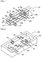
- positions S, S of the common electrode 17 facing the divided electrodes 16a and 16b are removed, as illustrated in Fig. 5. Note that the support members 18 are not shown for clarity.
- the reason for removing or etching the common electrode 17 in this embodiment is as follows.
- the etching of the divided electrodes 16a and 16b, which serve as detection electrodes, may variously produce adverse influences on signals to be detected.
- the etching of the common electrode 17, which serves as a driving electrode hardly changes signals to be detected. For this reason, it is desirable that the common electrode 17 be etched.
- the resonant frequencies f1 and f2 in the diagonal directions D1 and D2 substantially coincide with each other, the resonant frequency fx in the driving direction DX can be stabilized.
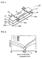
- Fig. 6 illustrates the impedance characteristics of the vibrating gyroscope 10 according to the embodiment of the present invention.
- Fig. 7 illustrates the impedance characteristics of the known vibrating gyroscope 100.
- the horizontal axis represents the frequency
- the vertical axis indicates the impedance.
- the frequency on the horizontal axis represents only a region around the resonance point.
- Figs. 6 and 7 reveal the following facts.
- the resonance point of the impedance characteristics in the driving direction DX is split into two points. This is because the resonance points of the impedance characteristic curves in the oblique directions D1 and D2 are separated from each other.
- the resonance points of the impedance characteristic curves in the two oblique directions D1 and D2 substantially coincide with each other, thus resulting in a single resonance point of the impedance characteristic in the driving direction DX.
- the vibrating gyroscope therefore generates stable vibrations and exhibits stable sensitivity and temperature characteristics.
- the vibrating gyroscope 10 is then adjusted so that a difference [fx - fy
- This step is performed by further etching the positions S, S of the common electrode 17 while the resonant frequencies in the diagonal directions D1 and D2 are kept at the substantial same value.
- the predetermined value is selected within the range of 20 ⁇
- the resonant frequency fx in the driving direction DX and the resonant frequency fy in the detecting direction DY are adjusted so that the resonant frequencies fx and fy satisfy the expression: 22 ⁇ fy - fx ⁇ 28 Hz .
- the output response characteristic of the vibrating gyroscope is indicated by the following expression.
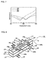
- positions S', S' at the divided electrodes 16a and 16b may be etched, as shown in Fig. 8.
- the divided electrodes 16a and 16b placed on the upper surface of the vibrator 11 or the common electrode 17 placed on the lower surface of the vibrator 11 is etched. Accordingly, even when the vibrating gyroscope is supported by using the frame-like base 20 shown in Fig. 2, the vibrator 11 can be easily etched to adjust the characteristics since it is free from obstacles on the upper surface or the lower surface of the base 20.
- the vibrator is formed by laminating two piezoelectric substrates that are polarized in mutually opposite directions along their thickness.
- the vibrator may be formed by laminating two piezoelectric substrates polarized in the same direction and by grounding an intermediate electrode, though it is not particularly shown.
- Various means for removing or etching the vibrator may be used, such as laser beam, a router, or sandblasting, according to the purpose of use or characteristics of the vibrating gyroscope.
- the resonant frequency in the driving direction there is some difference between the resonant frequency in the driving direction and the resonant frequency in the detecting direction.
- the two resonant frequencies may be adapted to substantially coincide with each other, in which case, the sensitivity is enhanced.
- a difference between the resonant frequencies improves the various characteristics, such as response. Accordingly, by considering the total performance of the gyroscope, it is preferable that the resonant frequencies be differentiated to adjust the gyroscope.
- the shape to be removed is not limited to two parallel slits in the longitudinal direction of the vibrator 11, as illustrated in Fig. 5 or Fig. 8. Only one slit may be formed, and the shape to be cut is not particularly restricted.
Landscapes
- Engineering & Computer Science (AREA)
- Manufacturing & Machinery (AREA)
- Physics & Mathematics (AREA)
- General Physics & Mathematics (AREA)
- Radar, Positioning & Navigation (AREA)
- Remote Sensing (AREA)
- Gyroscopes (AREA)
Applications Claiming Priority (6)
| Application Number | Priority Date | Filing Date | Title |
|---|---|---|---|
| JP23967797 | 1997-09-04 | ||
| JP239677/97 | 1997-09-04 | ||
| JP23967797 | 1997-09-04 | ||
| JP29839597A JP3285140B2 (ja) | 1997-09-04 | 1997-10-30 | 振動ジャイロの調整方法 |
| JP298395/97 | 1997-10-30 | ||
| JP29839597 | 1997-10-30 |
Publications (3)
| Publication Number | Publication Date |
|---|---|
| EP0900999A2 true EP0900999A2 (fr) | 1999-03-10 |
| EP0900999A3 EP0900999A3 (fr) | 2000-07-05 |
| EP0900999B1 EP0900999B1 (fr) | 2006-10-18 |
Family
ID=26534368
Family Applications (1)
| Application Number | Title | Priority Date | Filing Date |
|---|---|---|---|
| EP98116825A Expired - Lifetime EP0900999B1 (fr) | 1997-09-04 | 1998-09-04 | Gyroscope à vibration et sa méthode d' ajustement |
Country Status (5)
| Country | Link |
|---|---|
| US (1) | US6023973A (fr) |
| EP (1) | EP0900999B1 (fr) |
| JP (1) | JP3285140B2 (fr) |
| CN (1) | CN1091514C (fr) |
| DE (1) | DE69836180T2 (fr) |
Cited By (1)
| Publication number | Priority date | Publication date | Assignee | Title |
|---|---|---|---|---|
| WO2003025506A1 (fr) * | 2001-09-20 | 2003-03-27 | Honeywell International Inc. | Capteur inertiel micromecanique presentant un amortissement de resonance de detecteur d'ecart accru |
Families Citing this family (28)
| Publication number | Priority date | Publication date | Assignee | Title |
|---|---|---|---|---|
| CA2241929A1 (fr) * | 1996-10-29 | 1998-05-07 | Mitsui Chemicals, Incorporated | Gyroscope a vibrations |
| US6101878A (en) * | 1997-03-24 | 2000-08-15 | Denso Corporation | Angular rate sensor and method of improving output characteristic thereof |
| JP3341661B2 (ja) * | 1997-12-10 | 2002-11-05 | 株式会社村田製作所 | 振動ジャイロ |
| JP2000002539A (ja) * | 1998-06-15 | 2000-01-07 | Tokai Rika Co Ltd | 平行平板型振動ジャイロ及び平行平板型振動ジャイロ装置 |
| US6271985B1 (en) | 1998-08-06 | 2001-08-07 | Fujitsu Limited | Flanged cover for a low profile magnetic disk apparatus |
| JP3494096B2 (ja) * | 1999-11-05 | 2004-02-03 | 株式会社村田製作所 | 振動ジャイロ |
| US6621194B1 (en) * | 1999-11-15 | 2003-09-16 | Matsushita Electric Industrial Co., Ltd. | Piezoelectric element having thickness shear vibration and mobile communication device using the same |
| JP3613117B2 (ja) * | 2000-02-23 | 2005-01-26 | 株式会社村田製作所 | 振動子及びそれを用いた振動ジャイロ及びそれを用いた電子装置 |
| JP3656544B2 (ja) * | 2000-11-10 | 2005-06-08 | 株式会社村田製作所 | 複合振動子及びそれを用いた振動ジャイロ、及び複合振動子の製造方法 |
| JP2002228449A (ja) * | 2001-01-29 | 2002-08-14 | Murata Mfg Co Ltd | 振動ジャイロの製造方法 |
| JP2002250630A (ja) * | 2001-02-26 | 2002-09-06 | Murata Mfg Co Ltd | 振動子支持構造およびそれを用いた振動ジャイロおよびそれを用いた電子装置 |
| JP3741041B2 (ja) * | 2001-05-09 | 2006-02-01 | 株式会社村田製作所 | 振動ジャイロおよびそれを用いた電子装置 |
| JP4305623B2 (ja) * | 2002-03-13 | 2009-07-29 | セイコーエプソン株式会社 | 振動子および振動型ジャイロスコープ |
| JP4288914B2 (ja) * | 2002-08-21 | 2009-07-01 | パナソニック株式会社 | 共振デバイスの製造方法 |
| DE10317158B4 (de) * | 2003-04-14 | 2007-05-10 | Litef Gmbh | Verfahren zur Ermittlung eines Nullpunktfehlers in einem Corioliskreisel |
| DE10317159B4 (de) * | 2003-04-14 | 2007-10-11 | Litef Gmbh | Verfahren zur Kompensation eines Nullpunktfehlers in einem Corioliskreisel |
| DE10360962B4 (de) * | 2003-12-23 | 2007-05-31 | Litef Gmbh | Verfahren zur Quadraturbias-Kompensation in einem Corioliskreisel sowie dafür geeigneter Corioliskreisel |
| US7392702B2 (en) * | 2005-08-08 | 2008-07-01 | Litton Systems Inc. | Method for modifying the location of nodal points of a vibrating beam |
| CN101258382B (zh) * | 2005-11-21 | 2011-03-30 | 株式会社村田制作所 | 振动器及其制作方法 |
| CN101339026B (zh) * | 2008-08-14 | 2010-09-22 | 上海交通大学 | 具有正方形通孔压电振子的全固态双轴陀螺仪 |
| CN101339028B (zh) * | 2008-08-14 | 2010-08-18 | 上海交通大学 | 具有“回”型槽结构压电振子的全固态双轴陀螺仪 |
| CN101339029B (zh) * | 2008-08-14 | 2011-06-08 | 上海交通大学 | 具有“回”型柱状体振子磁致伸缩压电陀螺仪 |
| CN101339027B (zh) * | 2008-08-14 | 2010-12-15 | 上海交通大学 | 具有长方体振子的全固态双轴磁致伸缩压电陀螺仪 |
| CN101339030B (zh) * | 2008-08-14 | 2010-10-20 | 上海交通大学 | 具有磁致伸缩振子的双轴压电检测陀螺仪 |
| RU2417351C2 (ru) * | 2009-02-26 | 2011-04-27 | Открытое акционерное общество "Научно-исследовательский институт "Элпа" с опытным производством" (ОАО "НИИ "Элпа") | Способ балансировки пьезоэлектрического балочного биморфного чувствительного элемента вибрационного датчика угловой скорости |
| JP5327279B2 (ja) * | 2011-06-13 | 2013-10-30 | 株式会社デンソー | 超音波センサ装置 |
| JP6802125B2 (ja) * | 2017-08-24 | 2020-12-16 | 株式会社豊田中央研究所 | 振動ジャイロ |
| CN110300263B (zh) * | 2019-06-28 | 2021-06-08 | Oppo广东移动通信有限公司 | 陀螺仪处理方法和装置、电子设备、计算机可读存储介质 |
Family Cites Families (8)
| Publication number | Priority date | Publication date | Assignee | Title |
|---|---|---|---|---|
| JPH02298812A (ja) * | 1989-05-12 | 1990-12-11 | Murata Mfg Co Ltd | 振動ジャイロ |
| JPH02260909A (ja) * | 1989-03-31 | 1990-10-23 | Kyocera Corp | 圧電振動子 |
| JPH03149913A (ja) * | 1989-11-06 | 1991-06-26 | Fujitsu Ltd | 圧電振動子 |
| JP3292934B2 (ja) * | 1992-04-10 | 2002-06-17 | エヌイーシートーキン株式会社 | 圧電振動ジャイロ及び圧電振動ジャイロの共振周波数の調整方法 |
| US5430342A (en) * | 1993-04-27 | 1995-07-04 | Watson Industries, Inc. | Single bar type vibrating element angular rate sensor system |
| JP2780643B2 (ja) * | 1994-06-03 | 1998-07-30 | 株式会社村田製作所 | 振動ジャイロ |
| JPH09178487A (ja) * | 1995-12-22 | 1997-07-11 | Nikon Corp | 圧電振動角速度計用振動子の共振周波数調節方法 |
| US5765046A (en) * | 1994-08-31 | 1998-06-09 | Nikon Corporation | Piezoelectric vibration angular velocity meter and camera using the same |
-
1997
- 1997-10-30 JP JP29839597A patent/JP3285140B2/ja not_active Expired - Lifetime
-
1998
- 1998-09-03 US US09/146,795 patent/US6023973A/en not_active Expired - Lifetime
- 1998-09-04 EP EP98116825A patent/EP0900999B1/fr not_active Expired - Lifetime
- 1998-09-04 DE DE69836180T patent/DE69836180T2/de not_active Expired - Lifetime
- 1998-09-04 CN CN98119105A patent/CN1091514C/zh not_active Expired - Lifetime
Cited By (2)
| Publication number | Priority date | Publication date | Assignee | Title |
|---|---|---|---|---|
| WO2003025506A1 (fr) * | 2001-09-20 | 2003-03-27 | Honeywell International Inc. | Capteur inertiel micromecanique presentant un amortissement de resonance de detecteur d'ecart accru |
| US6598475B2 (en) | 2001-09-20 | 2003-07-29 | Honeywell International Inc. | Micromechanical inertial sensor having increased pickoff resonance damping |
Also Published As
| Publication number | Publication date |
|---|---|
| CN1091514C (zh) | 2002-09-25 |
| JPH11142155A (ja) | 1999-05-28 |
| JP3285140B2 (ja) | 2002-05-27 |
| US6023973A (en) | 2000-02-15 |
| EP0900999B1 (fr) | 2006-10-18 |
| DE69836180D1 (de) | 2006-11-30 |
| CN1210255A (zh) | 1999-03-10 |
| EP0900999A3 (fr) | 2000-07-05 |
| DE69836180T2 (de) | 2007-01-25 |
Similar Documents
| Publication | Publication Date | Title |
|---|---|---|
| US6023973A (en) | Vibrating gyroscope and adjusting method therefor | |
| EP0649002B1 (fr) | Gyroscope de vibration | |
| JP2780643B2 (ja) | 振動ジャイロ | |
| JP2005527783A (ja) | 電子整列および同調を有するマイクロジャイロスコープ | |
| US5837895A (en) | Vibrating gyroscope including a piezoelectric substrate polarized by a polarization inversion phenomenon | |
| US6907783B2 (en) | Vibrating gyroscope and angular velocity sensor | |
| US6201341B1 (en) | Vibrator for detecting angular velocities about two axes and vibrating gyroscope having the same | |
| EP0800058B1 (fr) | Gyroscope à vibration | |
| EP0563761A1 (fr) | Vibrateur avec des arêtes calibrés | |
| JPH03150914A (ja) | 振動子 | |
| EP0834719B1 (fr) | Méthode pour régler la caractéristique de température d'un gyroscope à vibration | |
| JP3649090B2 (ja) | 振動ジャイロ用振動子及びそれを用いた振動ジャイロ及びそれを用いた電子装置 | |
| JP3767212B2 (ja) | 振動ジャイロの支持構造および支持方法 | |
| JP2005345404A (ja) | 圧電振動ジャイロ用振動子及びその製造方法 | |
| JP4309814B2 (ja) | 圧電振動ジャイロ用振動子の調整方法 | |
| JP3293487B2 (ja) | 振動ジャイロ | |
| EP0563762B1 (fr) | Gyroscope vibrateur dont les éléments piézoélectriques se trouvent près noeuds vibratoires | |
| EP0684450B1 (fr) | Structure de support d'un vibreur | |
| JP3371608B2 (ja) | 振動ジャイロ | |
| JPH0914972A (ja) | 音片形振動ジャイロ | |
| JP3304722B2 (ja) | 振動ジャイロ | |
| JPH0854244A (ja) | 振動ジャイロ | |
| JPH0791963A (ja) | 振動ジャイロ | |
| JPH1062178A (ja) | 振動ジャイロ | |
| JPH0791959A (ja) | 振動ジャイロ |
Legal Events
| Date | Code | Title | Description |
|---|---|---|---|
| PUAI | Public reference made under article 153(3) epc to a published international application that has entered the european phase |
Free format text: ORIGINAL CODE: 0009012 |
|
| 17P | Request for examination filed |
Effective date: 19980904 |
|
| AK | Designated contracting states |
Kind code of ref document: A2 Designated state(s): DE FR GB SE |
|
| AX | Request for extension of the european patent |
Free format text: AL;LT;LV;MK;RO;SI |
|
| PUAL | Search report despatched |
Free format text: ORIGINAL CODE: 0009013 |
|
| AK | Designated contracting states |
Kind code of ref document: A3 Designated state(s): AT BE CH CY DE DK ES FI FR GB GR IE IT LI LU MC NL PT SE |
|
| AX | Request for extension of the european patent |
Free format text: AL;LT;LV;MK;RO;SI |
|
| RIC1 | Information provided on ipc code assigned before grant |
Free format text: 7G 01C 19/56 A, 7H 01L 41/09 B, 7H 03H 9/02 B |
|
| AKX | Designation fees paid |
Free format text: DE FR GB SE |
|
| 17Q | First examination report despatched |
Effective date: 20050617 |
|
| GRAP | Despatch of communication of intention to grant a patent |
Free format text: ORIGINAL CODE: EPIDOSNIGR1 |
|
| GRAS | Grant fee paid |
Free format text: ORIGINAL CODE: EPIDOSNIGR3 |
|
| GRAA | (expected) grant |
Free format text: ORIGINAL CODE: 0009210 |
|
| AK | Designated contracting states |
Kind code of ref document: B1 Designated state(s): DE FR GB SE |
|
| REG | Reference to a national code |
Ref country code: GB Ref legal event code: FG4D |
|
| REF | Corresponds to: |
Ref document number: 69836180 Country of ref document: DE Date of ref document: 20061130 Kind code of ref document: P |
|
| PG25 | Lapsed in a contracting state [announced via postgrant information from national office to epo] |
Ref country code: SE Free format text: LAPSE BECAUSE OF FAILURE TO SUBMIT A TRANSLATION OF THE DESCRIPTION OR TO PAY THE FEE WITHIN THE PRESCRIBED TIME-LIMIT Effective date: 20070118 |
|
| EN | Fr: translation not filed | ||
| PLBE | No opposition filed within time limit |
Free format text: ORIGINAL CODE: 0009261 |
|
| 26N | No opposition filed |
Effective date: 20070719 |
|
| RAP2 | Party data changed (patent owner data changed or rights of a patent transferred) |
Owner name: MURATA MANUFACTURING CO., LTD. |
|
| PG25 | Lapsed in a contracting state [announced via postgrant information from national office to epo] |
Ref country code: FR Free format text: LAPSE BECAUSE OF FAILURE TO SUBMIT A TRANSLATION OF THE DESCRIPTION OR TO PAY THE FEE WITHIN THE PRESCRIBED TIME-LIMIT Effective date: 20070601 |
|
| GBPC | Gb: european patent ceased through non-payment of renewal fee |
Effective date: 20070904 |
|
| PG25 | Lapsed in a contracting state [announced via postgrant information from national office to epo] |
Ref country code: GB Free format text: LAPSE BECAUSE OF NON-PAYMENT OF DUE FEES Effective date: 20070904 Ref country code: FR Free format text: LAPSE BECAUSE OF FAILURE TO SUBMIT A TRANSLATION OF THE DESCRIPTION OR TO PAY THE FEE WITHIN THE PRESCRIBED TIME-LIMIT Effective date: 20061018 |
|
| PGFP | Annual fee paid to national office [announced via postgrant information from national office to epo] |
Ref country code: DE Payment date: 20170928 Year of fee payment: 20 |
|
| REG | Reference to a national code |
Ref country code: DE Ref legal event code: R071 Ref document number: 69836180 Country of ref document: DE |