EP0901768A1 - Wannenträger - Google Patents
Wannenträger Download PDFInfo
- Publication number
- EP0901768A1 EP0901768A1 EP98111952A EP98111952A EP0901768A1 EP 0901768 A1 EP0901768 A1 EP 0901768A1 EP 98111952 A EP98111952 A EP 98111952A EP 98111952 A EP98111952 A EP 98111952A EP 0901768 A1 EP0901768 A1 EP 0901768A1
- Authority
- EP
- European Patent Office
- Prior art keywords
- tub support
- section
- sub
- wall
- walls
- Prior art date
- Legal status (The legal status is an assumption and is not a legal conclusion. Google has not performed a legal analysis and makes no representation as to the accuracy of the status listed.)
- Granted
Links
Images


Classifications
-
- A—HUMAN NECESSITIES
- A47—FURNITURE; DOMESTIC ARTICLES OR APPLIANCES; COFFEE MILLS; SPICE MILLS; SUCTION CLEANERS IN GENERAL
- A47K—SANITARY EQUIPMENT; ACCESSORIES THEREFOR, e.g. TOILET ACCESSORIES
- A47K3/00—Baths; Showers; Appurtenances therefor
- A47K3/16—Devices for fastening baths to floors or walls; Adjustable bath feet ; Lining panels or attachments therefor
- A47K3/1605—Hard foam bathtub supports
Definitions
- the invention relates to tub support with angled mutually extending walls, for example two Longitudinal walls and two transverse walls, which tub support consists of several sub-elements and kits is composed, the sub-elements made of rigid foam, such as particulate foam in particular, are shaped and by means of undercuts Projections are locked against each other.
- a tub support of this type is known from DE-PS 37 40 451 known.
- the sub-elements are each as Longitudinal elements, transverse walls or designed as a floor.
- the object of the invention is a generic Tub support safe to handle while maintaining strength to train.
- a sub-element a essentially complete wall and a section has a wall. This leaves room for one Addition in the sense of a module solution. It is also envisaged that a partial element is a complete wall and at both ends of the same in an integral connection each a section of another at an angle to it Wall.
- a sub-element has a bottom portion. In addition to a vertically oriented stabilization occurs also a horizontal stabilization close to the ground. Here too there is corner stabilization. It can do so be proceeded that the bottom section only on one the walls are molded.
- the bottom section connecting formations has for connection to another Bottom section.
- the further bottom section is expedient arranged on another sub-element. So equal joining partners are created.
- a wall section of a partial element by means of an intermediate wall section with a further wall element is connected.
- Such intermediate sections are in the valid different dimensional framework such tub support kept ready.
- the basic concept of the tub support is the intermediate section formed essentially bottom free.
- a Bottom section of a sub-element by means of a Intermediate floor section with a further floor section connected is.
- An embodiment of even independent meaning is seen in the fact that the Intermediate wall section a recess for receiving an overflow pipe.
- the corresponding pre-assembly is interesting on the market and even modular; also can adapt to certain pipe diameters be made without the basic body of the To change the shape of the tub support as a whole.
- the measure is then that the partition section integral with a floor is trained.
- a design becomes interesting in that that the intermediate section is two sections opposite Has walls that by means of a integrally molded bottom portion are connected. So is a profile disc oriented in the longitudinal direction reached. Your docking on the two-sided sub-elements can again be made using the undercuts have projections.
- the sunk Section can be reserved for cable routing be, so that no related rework on Tub support may be required. That is advantageous Sinking a continuous channel that is open at the end. In order to easily connect to the assembly opening, the sink is a continuous, end open gutter. It is further proposed that the intermediate sections one opposite the rest of the floor sunk, approximately parallel to the direction of extension of the wall extending section exhibit. Here is a line section. It is also convenient that in the groove across to her Longitudinal extension a break-out stabilizing wall is molded. In this way the gutter is one certain notch break function taken. Next is from Advantage that the projections to the composition in Direction of the longitudinal extension of the walls are.
- a Projection is designed as a swivel hook and opposite in an assigned end face of a partial element there is a pivoting opening. This leads to a good gripping attack. Alternatively can also be done so that the pivoting opening and the pivoting projection taken for itself also a connection by shifting the direction of extension of the walls. That comes a bayonet-like solution. Further Details are that a head start is designed as a locking projection and in a locking recess lies in. The latter means can be spaced to the swivel hook position.
- Locking projection or a locking rib in the locking recess is formed and that in the recess or in the locking projection an associated locking recess realized is.
- a corresponding recess for a projection is trained.
- the insertion position of the latching Parts can be easily secured by a part element essentially transverse to the direction of extension of the Walls formed an elongated projection is. The procedure is then that of a partial element with integrally molded bottom section to the bottom section assigned plug-in projection is formed.
- Prefers is further that a wall-side recess of the Partial element in whole or in part to the inside of the tub support is closed. Such a plotter Closure is in the rounding area of the bottom section.
- Such a rounding area is the concave contour the corresponding convex fee contour of the one to be used Tub or the like.
- the closure at two, assigned to different wall sections, however transverse to the direction of extension of a wall section opposite recesses with a view Tub support interior is formed only once.
- the receiving openings can be defined as Plug-in area can be used. Because the floor even less than load-bearing, rather than insulating Element acts, it is even possible that the receiving opening is designed as a through opening. It can have a large number of receiving openings in one element be provided.
- Such a receiving opening is expediently gutter-like and essentially transverse to the Walls are trimmed.
- the receiving openings can be used to assign an insert, which accordingly one adapted to the receiving opening Foot.
- An insert can have multiple feet Have plug-in projections.
- About such an insert relining can be compared to that in the tub support interior carry out the tub to be used.
- Such relines can be supportive.
- a Special function of corresponding inserts results advantageously in that two feet of the same Insert part in two receiving openings different Sub-elements are included. That can go as far as to a the parts firmly holding or clinging to each other Clamp function go.
- a structurally favorable Further training of the tub support is thereby further realizes that the assembly opening through a cover part is closable and that the cover part of two sections of cover parts clamped or latched together consists.
- the division of the otherwise relatively thick Cover part favors its space-saving accommodation. Nevertheless, in the unified state such cover parts accustomed to stability. It can go to a fundamental property.
- This Cover part is taking into account the so-called Vario type of tub supports, of course, optionally for both mounting openings applicable. It's also cheap that the cover part with overall plate-like training consisting of two cover sections that complement each other in panel thickness consists. So the cover remains coherent. It is particularly favorable that the cover part is partially chamfered at its corners is.
- the cover has three bevelled and one rectangular corner. It remains with a right-angled assembly opening Grip openings close to the corner zone, for example in terms of space requirements a finger.
- the cover can be so if necessary conveniently lift out of the assembly opening.
- a right-angled corner can act as a "key", so that with the same assembly opening contour only suitable for operation coordinated cover parts assigned become.
- the two sub-elements are quasi can be inserted into each other forming a cuboid. It is provided that the gutter of a partial element as a groove for a carrier trough edge section of the other sub-element serves and vice versa.
- the result is advantageous stiffening effect even if the Gap in the longitudinal direction of the tub support only on one Sub-section is filled by a sub-element. It there is also sufficient load-bearing area, according to the oblique division of the plate-like cover part Wedge pieces that grow the inner wall Take into account the slope towards the bottom of a tub support. The bevel area is thus in the packaging state supporting bridging. It happens even with constricting forces not to break through a shrink film. There is a sophisticated form of furniture packaging that saves space nested tub support.
- the connecting shoe is designed like a bridge, wherein the form-fitting recess is formed in the bridge piers are.
- the connecting shoe made of solid material will be produced. Sufficient is thought here hard plastic, cardboard or even metal. To be there nevertheless a support surface of the same material throughout to implement on the tub support continued as follows, that the connecting shoe has an opening on the top in which a foam wall section protrudes.
- a corresponding connecting shoe is further designed so that it is U-shaped in a cross section down is designed to open. It goes without saying The outside of this contour has the same profile as the rest of the edge the tub support.
- This barrier-like effect finds its counterpart in already existing grooves of the sub-elements to be connected or self-tapping when assigning.
- the bends in Continue barbs The latter avoid crawling back from the operational assignment position of the connecting shoe.
- the barbs provide at the same time an increase in the area of the bends. It there is more wing against separating pull effect.
- the tub support of all exemplary embodiments consists of Rigid plastic foam, in particular particle foam (EPP, EPS).
- EPP particle foam
- the tub support can be made up of several sub-elements T assemble as a kit as well as by corresponding profiles Complementary parts on bathtubs of various switch off the usual body measurements.
- the partial elements T are docked by means of undercuts having protrusions 1.
- the corresponding plug connection can, based on a flat footprint 3 of Tub support, be oriented vertically or horizontally. With the first-mentioned assignment, the recordings are 2 expediently against an upper edge 4 of the tub support closed and the projections 1 accordingly shortened.
- the plug connection is defined as a stop.
- the docking areas are at a corner.
- the corners of the Tub support are designated 5. You are part of the Wand W.
- rectangular plan having the shape of the tub support the wall W has two longitudinal walls 6 and two transverse walls 7. Both are aligned essentially in parallel.
- a sub-element T has at least one integral connection two sections a of the angled to each other, essentially vertically aligned walls, say longitudinal walls 6 or transverse walls 7.
- Ü essentially vertically aligned walls
- Such a section a can be significantly smaller than a longitudinal wall 6 or transverse wall 7. However, there is a massive elbow in front. On the other hand, it can also be proceeded so that a sub-element T in substantially complete wall 6 and 7 is detected and angled away a section a of a wall.
- This is the case when intermediate sections Z in the context of a Module system should be added. It can here, as can be seen, for example, from FIG. 1, to cross usable partition sections Z act. They are designed according to the wall profile and in the same Way equipped with projections 1 and 2 recordings. 1 is over one or two partition sections Z causes an extension of the longitudinal walls 6.
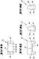
- the second embodiment (see, for example 9) relies on a multi-part structure of the transverse walls 7, by there an intermediate wall section Z essentially vertically oriented is introduced.
- the same is also true of a bottom 8 of the tub support possible by this also an intermediate floor section Z 'receives.
- Corresponding projections 1 and 2 recordings are on Section b of the floor 8 is taken into account as well as on Intermediate floor section Z of the floor 8 to be inserted.
- Each sub-element T of the tub support according to the second Embodiment accordingly has a complete Wall, here the entire longitudinal wall 6, and at both ends the same in an integral connection section a of in addition angled wall, here the proportional Transverse wall 7, on.
- the fixed Floor section b only on one of the walls, for example the one longitudinal wall 6, is formed, again here so that the bottom portion b docking connection formations has the same connection to the foot area the other wall or, as in principle explained on the further bottom section b, which then another sub-element T would be realized.
- transverse walls 7 assignable partition wall section Z up to on a floor-side fillet or shoulder 9 floor-free educated.
- This intermediate wall section Z faces the inside of the tub support a recess 10. This is where it comes from Overflow pipe of the bathtub drain under.
- the recess is in the form of a trapezoidal cross-section Vertical trough realized. The latter goes over the mentioned shoulder 9 on the bottom in one in the end regions the opening of the tub considered 11 over.
- a U-shaped profile forming intermediate sections Z represent the base 8 with respect to the U-web and with respect to of the essentially vertically aligned, each other opposite U-legs the walls of this Formed.
- a complete assembly opening 11 is circumscribed.
- the assembly opening is sufficient 11, however, not to the docking level of the intermediate section Z. Rather, a floor bridge B in remains Direction of extension arrow x of the wall W, here the longitudinal walls 6.
- the between two opposite wall sections of the longitudinal walls 6 extending floor bridge B has a dimension that is smaller than that in the same Direction of the opening dimension of the assembly opening 11.
- the width of the web-like floor bridge B can be about half the size of the opening.
- the Floor bridge B acts as a footbridge in the end area of the Longitudinal walls 6. It acts as a frame.
- This too Medium proves to be gentle on the corner of the partial element T.
- This is essentially perpendicular to the direction of extension x opening dimensions of the wall sections the mounting opening larger than that in the direction of extension x of the wall sections measured dimension the floor bridge B. In this regard it is practically the entire floor width created opening.
- the Partially recessed bottom area of the tub support educated. Regarding the sinking it is about around a gutter 12. It covers at least the area of the Floor bridge B. However, a continuous one is preferred Alignment of said sinking or groove 12 parallel to the direction of extension of the walls, more precisely Longitudinal walls 6, at the foot of which it runs.
- the module system has a corresponding counterpart.
- This is embodied in that the intermediate sections Z one that sinks in relation to the rest of the floor surface, approximately parallel to the direction of extension x the walls, here also the longitudinal walls 6, extending Have section.
- the gutter 12 continues congruently.
- the basic version of the tub support can be simple by assembling the two shovel-like Sub-elements T are created.
- This type of docking will explained on an airfoil-like partial element T and an intermediate section to be assigned in the direction of extension x Z. This is close, that is not far below the edge 4 of the intermediate section Z a projection 1 is formed, which is hook-shaped is. His hooked nose points upwards. The hook back is curved so that the projection 1 of the intermediate section Z hooking into the next sub-element T can swing in.
- the corresponding swivel opening here forms the receptacle 2 14 and pivoting opening 15 are contoured so that the bottom area of the intermediate section Z in one Bow y swings around the docking point above.
- both the male-like pivoting projection 14 as well as the die-like pivoting opening 15 extends across the entire wall width, i.e. to is open to the outside and inside of the same, the plug connection can also be a Connection by moving the parts to be connected reached across the direction of extension x of the walls become.
- the intermediate section Z has both functional parts on, namely on its one, the sub-element T facing stand 16 the pivoting projection and on its other end face facing away from this area 17 the pivoting opening 15 for coupling the next intermediate section or the other Sub-element T.
- the lateral end edges of the plug-in projection 20 lie in front of corresponding side edges of the recess 23. In such a facility, the tub support so well and important for the action, held together.
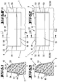
- FIGS. 25 and 26 The variant according to FIGS. 25 and 26 is in principle same, also with regard to a cross plug limit.
- Both solutions have a recess 23 on the wall of the sub-element T closed to the tub support interior. It can be a partial closure act (see Fig. 25).
- the recess 23 has one vertical blocking surface 25 Section of the projection 1. Said locking surface 25 is set so low that with operational coupling External and internal walls of parts T and Z together align at the same level.
- the second variant of the fourth embodiment shows a much larger root the projection 1.
- the undercuts 24 are accordingly both downwards and upwards directed.
- the recess 23 is adapted in outline.
- the height extension of this projection 1 corresponds at least a quarter of the height of the wall W of the tub support.
- the illustrated embodiment looks even a height extension of slightly more than that Half the height of a wall W.
- the surface of the bottom 8 of the parts T and Z is lower than the counter support 26. This allows a comfortable bayonet-type latching of the to be coupled Parts.
- the recess 23 is preferably larger Material accumulation.
- the closure in the Rounding region 27 of the base section realized, namely both the bottom 8 of the sub-element T as also the bottom 8 of the intermediate section Z. proceeded so that the closure at two, different Wall sections assigned, but transversely opposite to the direction of extension x of the wall section Recesses 23 with respect to the tub support interior is trained only once. Prefers here you choose the side that is convenient from the one Bevelling of the longitudinal wall 6 allowing foot underfoot is not affected.
- the sub-element is similar to the solution according to FIG T assigned a recess 23 according to FIG. 25. However, it is designed to run continuously and works with a strip-shaped seat on the next part Plug projection 22 together. These funds are too on both end faces 16, 17 of the intermediate section Z provided and stabilize the joint area of the added Soils 8.
- This tub support is basically that of the first Embodiment closer, only that there sloping front wall is missing.
- the longitudinal walls 6 are outside rather kept parallel to the room. Accordingly, it also does not apply the precaution, the assembly opening 11 in both end areas of the floor. Otherwise, the reference numbers applied analogously, partly without textual repetitions.
- Training is there before all the measure that a sub-element T has a receiving opening 29 has. That is in the present case the assignment of a mounting opening 11 in addition and formed separately from the mounting opening 11.
- the Receiving opening 29 connects interrupted by web.
- the Receiving opening 29 is designed as a through opening, i.e. it goes to the bottom of the bottom 8 through that rests on bars or a lattice structure. It is integrally formed on the parts T and Z and Z '.
- a large number of receiving openings 29 can be seen realized. They are in compliance with a certain one Reports.
- the width of the individual intake openings 29 corresponds approximately to twice the width between webs 30 remaining in receiving openings 29.
- receiving openings 29 assignable inserts 31 would allow.
- the across the walls, i.e. Longitudinal walls 6, receiving openings 29 are covered across the web by the insert parts 31.
- Such insert parts 31 can optionally be used supportive relining of those to be lowered Complete the tub.
- the insert parts 31 point to the receiving opening adjusted foot 32 on. There are inserts 31 shown, which have two identical feet 32 and those that have four identical legs 32.
- Feet 32 carrying insert 31 act as a joint clamp. This is done in such a way that two feet 32 the same insert 31 in two adjacent receiving openings Intervene 29 different sub-elements T. In a figurative sense, this also applies to the joint areas between sub-element T and intermediate section Z.
- the gap width between two feet 32 corresponds two web widths.
- the partial elements stabilized by a high corner strength T can be due to a skillful Piece by piece also in a space-saving packaging arrangement V transfer by an otherwise the tub support space forming part element free space F as a box space is used for a further sub-element T etc. It is refer to Figure 8.
- the underfloor area of the floor 8 of the sub-elements T is opposite in the outward direction directed.
- the longitudinal walls 6 are under sections Use of the horizontal insertion depth of the box room running parallel. It is in front of a transverse wall 7th on the inside a free space section in the form of a space gap 33 takes into account that of the direction of extension measured length of the wall sections of the intermediate section Z corresponds.
- Such a packaging arrangement V is usually strapped or also in Foil wrapped, preferably in a shrink film shrink wrapped.
- the gutter 12 which acts as a conduit, carries also saves space, because the Channel 12 of a partial element T as a groove for one Beam trough edge section (edge 4) of the other section T serves and vice versa. That brings a clear one Congestion gain in the vertical shown. Also the tub support according to the fifth embodiment can be turned into an even more affordable one Transfer packaging arrangement V by the intermediate section there too Z with its one free end in the Assembly opening 11 protrudes and with its other free Ends in the mentioned transverse space gap.
- the sub-elements T of the tub support which is longitudinally divided here with respect to the Sections of the transverse walls 7 are offset from one another in a plane inserted here using the bay-like parts the open cut assembly opening 11.
- the others Intermediate wall sections Z etc can be found in the Figure 15 accommodate clear space F.
- the packaging arrangement V of the third exemplary embodiment which is based on a division of the tub support into four lies, opens up a stack like it 18 and 19 can be seen. Here is one space-saving nested in the same direction.
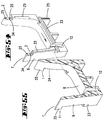
- FIG. 54 On the connecting sides of the sub-elements T is the in Figure 25 with 25 designated blocking area over a realized larger vertical section of the walls. It extends in a zone of the longitudinal wall 6 lying below the floor 8 and is practically only pierced by the crossing plug-in projections 22 together with the associated recess 23 in the attaching part. Said blocking surface 25 is, as shown in FIG. 54, also in the Area of the upper edge of the tub support, namely in the recording there 2, which in the usual Way the described projections 1 of the other sub-element T or partition Z section assigned are.
- the blocking area 25 is somewhat shorter, but full sufficiently provided.
- tub support according to the sixth embodiment further developed in that the in Mounting openings 11 located in both end regions can be closed are.
- a corresponding outline is used for this Cover part 36 (see FIG. 31). That can, like that Floor 8 itself, also have a supporting function.
- the particle foam, plate-like cover part 36 is in one plane larger area extension divided into two.
- the sections bear the reference symbol 36 ', 36' '. These are in plate thickness practically complementary to a cube slice Parts 36 ', 36' 'are clamped or latched together.
- strip-shaped bars facing each other can be used Serve webs 37. There is also a certain amount material-related frictional attachment of each other Portions 36 ', 36' 'assigned congruently.
- quadrangular cover part 36 at its corners partially beveled. There are three chamfered corners and one right corner.
- cover part 36 also used for packaging. It is in this regard refer to Figure 32. It has to be said that the cover part 36 is divided to form a wedge. Leave that resulting from the corresponding dividing line 38 in FIG 31 perceive. Taking into account the explanations with regard to the packaging arrangement V is space-saving Housing the cover part 36 also proceeded that an essentially vertical wall, in particular the longitudinal wall 6 of a partial element T a inclined wall, in particular longitudinal wall 6 of the is assigned to other sub-element T. It is on figure 35 referenced. This clearly leads to a free space in Form a wedge-shaped cross-section with gap spaces 39. They are according to the nesting Forend assignment of the sub-elements T in the opposite direction and opening offset.
- FIG. 36 to 40 Variant is embodied by joining projections 41 of the a sub-element T, the congruent with receding lying recesses 42 of the other interact. These are strip-like joining projections 41 and around knob-like joining projections 41. The latter are for example in the form of a barrel-like shape at both ends tapered cube.
- the joining fixture 42 is constructed and sized so that it becomes one effective clamping seat engagement comes.
- the strip-shaped Joining projections 41 which extend over the height of a extend corresponding sub-element end wall, are less exposed. A bar height is sufficient (seen of a few, for example 5 mm.
- strip-shaped protection against lateral jump Joining projections 41 is in the area of the edge 4 of the tub support formed another effective docking zone. This is done with the help of a joint Connection shoe 43. The is from above in the Edge 4 inserted.
- the connecting shoe 43 exercises here Bracket function and counteracts a tendency to separate the insertion direction counterhand.
- the connecting shoe 43 is made according to its basic design made of particle foam.
- the edge offers 4 on the assignment side with the material of the sub-elements T and optionally the partition section Z a material-identical pad for the edge of the tub to be suspended in the tub support.
- the connecting shoe 43 is bridge-shaped.
- the horizontal section 44 of the bridge part runs conforming to the edge. Go from the ends of this bridge part then essentially vertically aligned bridge piers 45 out. Between the bottom of the horizontal Section 44 and the insides of the bridge piers 45 is an underpass-like form-fitting recess 46.
- the towards the stand area 3 of the tub support open form-fit recess 46 has its matching Counterpart in the form of a vertically oriented tine. It consists of two single prongs 47 of the same size together. They are close to the edge and in the area of both End faces of the sub-elements T or intermediate sections Z trained. Groundbreaking, behind the Single prongs 47 lying, there is one Well 48. The latter corresponds with regard to the sub-elements T the negative shape of the bridge pier 45. With regard to the intermediate section Z, however, there is a Clearing double the size of the recess 48 in front. The addition is in plug direction x. Hereby there are two adjacent bridge pillars 45 two Connection shoes 43 under. This is the case here a double fugue before, as they result from the synopsis of Figures 38 to 42 can be easily imagined.
- the cross-sectional profile is the connecting shoes 43 that of the edge 4 adjusted. Also on the different wall course the longitudinal walls 6 are considered in terms of shape.
- FIGS. 47 to 53 A design modification of the connecting shoe described 43 results from FIGS. 47 to 53.
- the connecting shoe 43 consists of a hard part.
- a corresponding solid material hard cardboard, Plastic, even metal serve.
- This connecting shoe 43 has, seen in cross section, U-shaped shape.
- the U opening points in Direction of the stand area 3. It can be kind of rather Assign edge strips, this overlap the edge 4 from above, with the profiling the top of the edge, the inside of it and the outside overlap the edge.
- the edge 4 of the sub-elements T docked to one another has in the assignment area of the connecting shoe described 43 a joint-parallel engagement recess 56 on (see Figure 50). This applies at least to of bends 52, if not already provided is that the blade-like bends 52 emboss / cut such engagement openings 56 themselves. This can be done mechanically or thermomechanically. On the other hand, when it comes to shaping the Sub-elements T a light, the corresponding Joining contour for the connecting shoe 43 already beforehand form.
- the connecting shoe 43 from FIG. 47 ff points above it a special feature as far as the Area of the U-web 55 of this connecting shoe 43 Openings 57 are taken into account.
- the latter are through a foam wall section 58 of the rim 4 protrudes.
- the corresponding penetration level is that the top of the foam wall section 58 with the corresponding top of the edge 4 of the Sub-elements T are aligned in accordance with the cross-sectional contour.
- Two such window-like openings 57 are taken into account. Each lies well spaced apart and in the middle of the partial element T. In this way, the edge of the one to be found Tub a homogeneous, i.e. evenly aligned foam surface in front.
- foam wall section 58 also an isolating function. He lies like a bolt in a U-web 55 formed "Striking plate". The joint-facing are not active Cross sides of the long rectangular, window-shaped openings 57. So the longer extension is more effective Latch bodies available.
- FIGS. 47 to 49 A further development is then shown in FIGS. 47 to 49 evident, which is that the bends 52 continue in barbs 59. Show the latter Sawtooth structure.
- the steeper flank of the in line arranged barb 59 is horizontal, that is vertical to the pin assignment direction of the connecting shoe 43.
- the other flank is aligned to it.
- the corresponding gearing begins right at the free ends of the bends 52.
- FIGS. 51 and 53 A comparison of FIGS. 51 and 53 shows that the connecting shoe 43 is identical here is.
- Wall projection 60 of the U-leg lying on the outside 54 still comes in an outward-facing niche 61 of the engagement opening 56 under.
- Said niche is 61 51 towards the lower outer edge cut back due to skew.
- a tub support in which a partial element T a substantially complete wall and one Section a has a wall.
- a tub support in which a partial element T a complete wall and at both ends of the same in an integral connection a section a a further wall 7 standing at an angle thereto.
- Subject of the invention alone or in combination with the previously explained objects of importance is also a tub support, in which the sinking is a continuous, open end channel 12.
- Subject of the invention alone or in combination with the previously explained objects of importance is also a tub support, in which the intermediate sections Z one compared to the rest of the floor area sunk, approximately parallel to the direction of extension x section of the wall exhibit.
- Subject of the invention alone or in combination with the previously explained objects of importance is also a tub support, in which the projections 1 on the composition in the direction of the longitudinal extent x of the walls are formed.
- a tub support with a head start 1 is designed as a locking projection 18 and in a recess 19 is inserted.
- Subject of the invention alone or in combination with the previously explained objects of importance is also a tub support, on which on the Locking projection 18 or a locking rib in the locking recess 21 is formed, and that in the locking recess 19 or in the locking projection 18 an associated locking recess 20 is realized.
- Subject of the invention alone or in combination with the previously explained objects of importance is also a tub support, in which the locking rib 21 essentially transversely to the extension x of the walls is trained.
- a tub support in which the height extension a projection 1 at least a quarter corresponds to the height of a wall W.
- Subject of the invention alone or in combination with the previously explained objects of importance is also a tub support, in which a wall-side Recess 23 of the partial element T completely or is partially closed to the inside of the tub support.
- Subject of the invention alone or in combination with the previously explained objects of importance is also a tub support, in which the closure with two different wall sections assigned, but transverse to the direction x a recess 23 opposite a wall section with regard to a tub support interior only once is trained.
- a tub support in which a partial element T has a receiving opening 29, this in In the case of a mounting opening 11 additionally and separately to the mounting opening 11 is formed.
- Subject of the invention alone or in combination with the previously explained objects of importance is also a tub support, in which the receiving opening 29 is designed as a through opening.
- Subject of the invention alone or in combination with the previously explained objects of importance is also a tub support, in which a receiving opening 29 gutter-like and essentially across the walls are trending.
- Subject of the invention alone or in combination with the previously explained objects of importance is also a packaging arrangement in which an intermediate section Z with a free end in the Mounting opening 11 protrudes and with the other free end is accommodated in a transverse space gap 33.
- a substantially vertical wall in particular Longitudinal wall 6 of a sub-element T is an oblique one Wall, in particular longitudinal wall 6 of the other sub-element T is assigned leaving one in cross section wedge-shaped gap 39.
Landscapes
- Health & Medical Sciences (AREA)
- Public Health (AREA)
- Epidemiology (AREA)
- General Health & Medical Sciences (AREA)
- Floor Finish (AREA)
- Percussion Or Vibration Massage (AREA)
- Materials For Photolithography (AREA)
- Containers Having Bodies Formed In One Piece (AREA)
- Packages (AREA)
- Packaging Of Annular Or Rod-Shaped Articles, Wearing Apparel, Cassettes, Or The Like (AREA)
- Bathtubs, Showers, And Their Attachments (AREA)
Abstract
Description
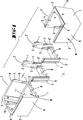
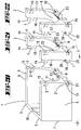
- Fig. 1
- einen aus Teilelementen zusammensetzbaren Wannenträger in perspektivischer Darstellung, gemäß erstem Ausführungsbeispiel,
- Fig. 2
- die Draufsicht auf den noch nicht zusammengefügten Wannenträger,
- Fig. 3
- den Schnitt gemaß Linie III-III in Figur 2, in die Gebrauchsstellung überführt,
- Fig. 4
- den Schnitt gemäß Linie IV-IV in Figur 2,
- Fig. 5
- den Schnitt gemäß Linie V-V in Figur 2,
- Fig. 6
- diesen Wannenträger in eine raumsparende Verpackungsanordnung überführt, das in Draufsicht zeigend,
- Fig. 7
- dasselbe in perspektivischer Darstellung,
- Fig. 8
- einen Querschnitt durch Figur 6, ohne Zwischenwandabschnitt,
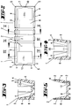
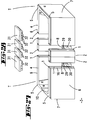
- Fig. 9
- einen aus Teilelementen zusammensetzbaren Wannenträger in Draufsicht, gemäß zweitem Ausführungsbeispiel,
- Fig. 10
- den Schnitt gemäß Linie X-X in Figur 9, in eine gebrauchsgerechte Stellung überführt,
- Fig. 11
- einen Zwischenwandabschnitt in Draufsicht,
- Fig. 12
- einen weiteren Zwischenwandabschnitt, gleichfalls in Draufsicht,
- Fig. 13
- einen Bodenzwischenabschnitt in Draufsicht,
- Fig. 14
- einen bezüglich der Wände und des Bodens zusammengefaßten Zwischenabschnitt,
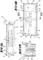
- Fig. 15
- den längsgeteilten Wannenträger in eine raumsparende Verpackungsanordnung überführt,
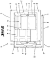
- Fig. 16
- einen aus Teilelementen zusammensetzbaren Wannenträger in Draufsicht, gemäß drittem Ausführungsbeispiel, viergeteilt,
- Fig. 17
- eine Stirnansicht aus einer Teilungsebene XVII-XVII in Figur 16 gesehen, noch nicht zusammengefügt,
- Fig. 18
- die Teilelemente in eine raumsparende Verpackungsanordnung überführt, und zwar in Draufsicht gesehen,
- Fig. 19
- den Schnitt gemaß Linie XIX-XIX in Figur 18,
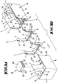
- Fig. 20
- einen aus Teilelementen zusammensetzbaren Wannenträger gemäß viertem Ausführungsbeispiel (nur eins ist dargestellt), mit Mitteln zum Andocken additiver Teilelemente in Form von Zwischenabschnitten, in perspektivischer Darstellung,
- Fig. 21
- einen Zwischenabschnitt in Perspektive,
- Fig. 22
- einen gleichen Zwischenabschnitt in Perspektive,
- Fig. 23
- einen partiell dargestellten Wannenträger gemäß viertem Ausfährungsbeispiel mit abgewandelten Mitteln zum Zusammensetzen additiver Teilelemente, in perspektivischer Darstellung,
- Fig. 24
- gleichfalls in schaubildlicher Wiedergabe einen passenden Zwischenabschnitt,
- Fig. 25
- einen Wannenträger mit abgewandelten Mitteln zum Zusammensetzen additiver Teilelemente in weiter abgewandelter Ausbildung,
- Fig. 26
- den zugehörigen Zwischenabschnitt, gleichfalls in perspektivischer Wiedergabe,
- Fig. 27
- einen aus Teilelementen zusammensetzbaren Wannenträger gemäß fünftem Ausführungsbeispiel in Perspektive,
- Fig. 28
- in schaubildlicher Darstellung zugehörige Boden-Einlegeteile,
- Fig. 29
- die Draufsicht auf den Wannenträger gemäß Figur 27,
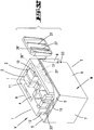
- Fig. 30
- einen aus Teilelementen zusammensetzbaren Wannenträger in perspektivischer Darstellung gemäß sechstem Ausführungsbeispiel,
- Fig. 31
- ein zugehöriges Abdeckteil für die Montageöffnung, ebenfalls in schaubildlicher Darstellung,
- Fig. 32
- diesen Wannenträger in eine raumsparende Verpackungsanordnung überführt, in perspektivischer Darstellung, wobei ein Abdeckteil-Teilstück als Raumfüller einem Spaltraum der Verpackungsanordnung zugeordnet wird,
- Fig. 33
- den Wannenträger in raumsparender Verpackungsanordnung, nun in Draufsicht,
- Fig. 34
- den Schnitt gemäß Linie XXXIV-XXXIV in Figur 33,
- Fig. 35
- den Schnitt gemäß Linie XXXV-XXXV in Figur 33,
- Fig. 36
- eine Innenansicht gegen das eine Teilelement des Wannenträgers,
- Fig. 37
- eine Innenansicht gegen das andere Teilelement, beide Darstellungen, weitestgehend schematisiert und abgewandelte Fügevorsprünge und Fügeausnehmungen zeigend, insofern eine Variante des sechsten Ausführungsbeispieles verkörpernd,
- Fig. 38
- eine Seitenansicht des einen Teilelements,
- Fig. 39
- eine Seitenansicht des anderen Teilelements,
- Fig. 40
- eine Seitenansicht des zugehörigen Zwischenabschnitts, sämtliche Darstellungen die Fügemittel gemäß Figur 36 und 37 aufweisend,
- Fig. 41
- eine der linksseitigen Fuge des Wannenträgers zuordbarer Verbindungsschuh, in Seitenansicht,
- Fig. 42
- einen der rechtsseitigen Fuge desselben zuordbaren Verbindungsschuh,
- Fig. 43
- den Verbindungsschuh in Seitenansicht, gegenüber Fig, 41 vergrößert,
- Fig. 44
- die Unteransicht des Verbindungsschuhs,
- Fig. 45
- einen einer im wesentlichen vertikalen Wand, insbesondere Längswand zuordbaren Verbindungsschuh in Stirnansicht,
- Fig. 46
- einen einer schräg verlaufenden Wand, insbesondere Längswand, des Wannenträgers zuordbaren Verbindungsschuh in Stirnansicht,
- Fig. 47
- in Seitenansicht, teilweise aufgebrochen, eine Variante des Verbindungsschuhs als Hartteil,
- Fig. 48
- eine Stirnansicht hierzu,
- Fig. 49
- die Draufsicht auf Figur 47,
- Fig. 50
- den Verbindungsschuh in dem Wannenträger zugeordneten Zustand, in Seitenansicht, die schräge Wand betreffend,
- Fig. 51
- den Schnitt gemäß Linie LI-LI in Figur 50,
- Fig. 52
- den Verbindungsschuh in dem Wannenträger zugeordneten Zustand, in Seitenansicht, die vertikale Wand betreffend,
- Fig. 53
- den Schnitt gemäß Linie LIII-LIII in Figur 52,
- Fig. 54
- in Perspektive eine Ansicht gegen das verbindungsseitige Ende des einen, in Figur 31 linksseitigen Teilelements und
- Fig. 55
- den diesbezüglichen Bereich des anderen Teilelements in querseitiger Einfügebereitschaftsstellung beider Teile.
Claims (10)
- Wannenträger mit winklig zueinander verlaufenden Wänden, beispielsweise zwei Längswänden (6) und zwei Querwänden (7), welcher Wannenträger aus mehreren Teilelementen (T) besteht und bausatzartig zusammengesetzt ist, wobei die Teilelemente aus Partikelschaumstoff geformt sind und mittels Hinterschneidungen aufweisender Vorsprünge (1) gegeneinander verrastet sind, dadurch gekennzeichnet, daß ein Teilelement (T) in integraler Verbindung mindestens zwei Abschnitte (a) der winklig zueinander stehenden, im wesentlichen vertikal ausgerichteten Wände (6,7) aufweist derart, daß bei einer Projektion eines Wandprofils auf die Eckverbindung der andere Abschnitt (a) einen Überstand (Ü) ausbildet.
- Wannenträger nach einem oder mehreren der vorhergehenden Ansprüche oder insbesondere danach, dadurch gekennzeichnet, daß der Bodenabschnitt (b) Verbindungsausformungen (1, 2) aufweist zur Verbindung mit einem weiteren Bodenabschnitt (b).
- Wannenträger nach einem oder mehreren der vorhergehenden Ansprüche oder insbesondere danach, dadurch gekennzeichnet, daß ein Wandabschnitt eines Teilelements (T) vermittels eines Zwischenwandabschnitts (Z) mit einem weiteren Wandelement verbunden ist.
- Wannenträger nach einem oder mehreren der vorhergehenden Ansprüche oder insbesondere danach, dadurch gekennzeichnet, daß der Zwischenwandabschnitt (Z) zwei Abschnitte gegenüberliegender Wände aufweist, die vermittels eines integral angeformten Bodenabschnitts (b) verbunden sind.
- Wannenträger nach einem oder mehreren der vorhergehenden Ansprüche oder insbesondere danach, dadurch gekennzeichnet, daß in einem Teilelement (T) bodenseitig eine vollständige Montageöffnung (11) ausgebildet ist, wobei eine freistehende, zwischen zwei gegenüberliegenden Wandabschnitten verlaufende Bodenbrücke (B) in Erstreckungsrichtung der Wandabschnitte ein Maß aufweist, welches kleiner ist als das in gleicher Richtung abgenommene Öffnungsmaß der Montageöffnung (11).
- Wannenträger nach einem oder mehreren der vorhergehenden Ansprüche oder insbesondere danach, dadurch gekennzeichnet, daß das im wesentlichen senkrecht zur Erstreckungsrichtung (x) der Wandabschnitte verlaufende Öffnungsmaß der Montageöffnung (11) größer ist als das in Erstreckungsrichtung der Wandabschnitte gemessene Maß der Bodenbrücke (B).
- Wannenträger nach einem oder mehreren der vorhergehenden Ansprüche oder insbesondere danach, dadurch gekennzeichnet, daß ein Vorsprung (1) als Einschwenkhaken (14) ausgebildet ist und gegenüberliegend in einer zugeordneten Stirnfläche (16) eines Teilelements (T) bzw. Zwischenabschnittes (Z) eine Einschwenköffnung (15) ausgebildet ist.
- Wannenträger nach einem oder mehreren der vorhergehenden Ansprüche oder insbesondere danach, dadurch gekennzeichnet, daß an einem Teilelement (T) mit integral angeformtem Bodenabschnitt ein dem Bodenabschnitt zugeordneter Steckvorsprung (22) ausgebildet ist.
- Verpackungsanordnung (V) eines zu einem Wannenträger oder Duschtassenträger zusammenfügbaren Teilelemente-Satzes, wobei die Teilelemente (T) aus Partikelschaumstoff geformt sind, dadurch gekennzeichnet, daß ein Teilelement (T) in integraler Verbindung mindestens zwei Abschnitte (a) von winklig zueinander stehenden, im zusammengefügten Zustand im wesentlichen vertikal ausgebildete Wände aufweist, wobei ein sonst den Wannenträgerinnenraum bildender Teilelemente-Freiraum (F) als Schachtelraum für ein weiteres Teilelement (T) genutzt ist.
- Wannenträger mit winklig zueinander verlaufenden Wänden, beispielweise zwei Längswänden (6) und zwei Querwänden (7), welcher Wannenträger aus mehreren Teilelementen (T) besteht und bausatzartig zusammengesetzt ist, wobei die Teilelemente (T) aus Hartschaumstoff, insbesondere Partikelschaumstoff bestehen und untereinander verbunden sind, gekennzeichnet durch zwei Teilelemente (T) an einem oberen Rand (4) übergreifenden Verbindungsschuh (43).
Priority Applications (1)
| Application Number | Priority Date | Filing Date | Title |
|---|---|---|---|
| DE29823888U DE29823888U1 (de) | 1997-09-15 | 1998-06-29 | Wannenträger |
Applications Claiming Priority (4)
| Application Number | Priority Date | Filing Date | Title |
|---|---|---|---|
| DE19740446 | 1997-09-15 | ||
| DE19740446 | 1997-09-15 | ||
| DE19806006A DE19806006A1 (de) | 1997-09-15 | 1998-02-16 | Wannenträger |
| DE19806006 | 1998-02-16 |
Publications (2)
| Publication Number | Publication Date |
|---|---|
| EP0901768A1 true EP0901768A1 (de) | 1999-03-17 |
| EP0901768B1 EP0901768B1 (de) | 2004-05-06 |
Family
ID=26039979
Family Applications (1)
| Application Number | Title | Priority Date | Filing Date |
|---|---|---|---|
| EP98111952A Expired - Lifetime EP0901768B1 (de) | 1997-09-15 | 1998-06-29 | Wannenträger |
Country Status (4)
| Country | Link |
|---|---|
| EP (1) | EP0901768B1 (de) |
| AT (1) | ATE265818T1 (de) |
| DK (1) | DK0901768T3 (de) |
| ES (1) | ES2216211T3 (de) |
Cited By (3)
| Publication number | Priority date | Publication date | Assignee | Title |
|---|---|---|---|---|
| GB2525236A (en) * | 2014-04-17 | 2015-10-21 | Trojan Plastics Ltd | A reinforcement block for the rim of a bath |
| EP3659479A3 (de) * | 2018-11-30 | 2020-09-09 | poresta systems GmbH | Wannenträger aus einem hartschaumstoff sowie zur versandanordnung gestapelte teile eines wannenträgers |
| CN117401282A (zh) * | 2023-03-15 | 2024-01-16 | 深圳Tcl新技术有限公司 | 一种显示屏的包装结构 |
Citations (6)
| Publication number | Priority date | Publication date | Assignee | Title |
|---|---|---|---|---|
| DE8703968U1 (de) * | 1987-03-17 | 1987-04-23 | Correcta GmbH, 3590 Bad Wildungen | Armaturenblock einer Wanneneinfassung aus Kunststoffschaum |
| DE8708684U1 (de) | 1987-06-23 | 1987-08-06 | Wesko GmbH Sanitär- und Baubedarf, 6121 Hesseneck | Bauteilesatz für einen Badewannenträger |
| DE3740451A1 (de) | 1987-11-28 | 1989-06-08 | Correcta Gmbh | Wannentraeger, insbesondere fuer bade- oder duschwannen |
| EP0640313A2 (de) * | 1993-08-31 | 1995-03-01 | Correcta GmbH | Wannenträger |
| DE29603236U1 (de) * | 1996-02-23 | 1997-06-26 | Correcta GmbH, 34537 Bad Wildungen | Wannenträger |
| EP0783862A1 (de) * | 1996-01-12 | 1997-07-16 | Kunststofftechnik Schedel GmbH | Wannenträgter für Bade- oder Duschwannen |
-
1998
- 1998-06-29 ES ES98111952T patent/ES2216211T3/es not_active Expired - Lifetime
- 1998-06-29 AT AT98111952T patent/ATE265818T1/de not_active IP Right Cessation
- 1998-06-29 DK DK98111952T patent/DK0901768T3/da active
- 1998-06-29 EP EP98111952A patent/EP0901768B1/de not_active Expired - Lifetime
Patent Citations (6)
| Publication number | Priority date | Publication date | Assignee | Title |
|---|---|---|---|---|
| DE8703968U1 (de) * | 1987-03-17 | 1987-04-23 | Correcta GmbH, 3590 Bad Wildungen | Armaturenblock einer Wanneneinfassung aus Kunststoffschaum |
| DE8708684U1 (de) | 1987-06-23 | 1987-08-06 | Wesko GmbH Sanitär- und Baubedarf, 6121 Hesseneck | Bauteilesatz für einen Badewannenträger |
| DE3740451A1 (de) | 1987-11-28 | 1989-06-08 | Correcta Gmbh | Wannentraeger, insbesondere fuer bade- oder duschwannen |
| EP0640313A2 (de) * | 1993-08-31 | 1995-03-01 | Correcta GmbH | Wannenträger |
| EP0783862A1 (de) * | 1996-01-12 | 1997-07-16 | Kunststofftechnik Schedel GmbH | Wannenträgter für Bade- oder Duschwannen |
| DE29603236U1 (de) * | 1996-02-23 | 1997-06-26 | Correcta GmbH, 34537 Bad Wildungen | Wannenträger |
Cited By (5)
| Publication number | Priority date | Publication date | Assignee | Title |
|---|---|---|---|---|
| GB2525236A (en) * | 2014-04-17 | 2015-10-21 | Trojan Plastics Ltd | A reinforcement block for the rim of a bath |
| GB2525236B (en) * | 2014-04-17 | 2021-03-24 | Trojan Plastics Ltd | A reinforcement block for the rim of a bath |
| EP3659479A3 (de) * | 2018-11-30 | 2020-09-09 | poresta systems GmbH | Wannenträger aus einem hartschaumstoff sowie zur versandanordnung gestapelte teile eines wannenträgers |
| CN117401282A (zh) * | 2023-03-15 | 2024-01-16 | 深圳Tcl新技术有限公司 | 一种显示屏的包装结构 |
| CN117401282B (zh) * | 2023-03-15 | 2025-11-21 | 深圳Tcl新技术有限公司 | 一种显示屏的包装结构 |
Also Published As
| Publication number | Publication date |
|---|---|
| DK0901768T3 (da) | 2004-09-13 |
| ATE265818T1 (de) | 2004-05-15 |
| EP0901768B1 (de) | 2004-05-06 |
| ES2216211T3 (es) | 2004-10-16 |
Similar Documents
| Publication | Publication Date | Title |
|---|---|---|
| DE1486511A1 (de) | Einsatzkasten | |
| DE1509841A1 (de) | Tragbarer Fussboden | |
| DE3635288A1 (de) | Tischsystem | |
| DE2708167A1 (de) | Schublade aus kunststoff | |
| DE7816302U1 (de) | Schublade | |
| DE2950138C2 (de) | Plattensystem, insbesondere für Behälter od.dgl. | |
| DE202012003483U1 (de) | Besteckeinsatz | |
| DE102018121479A1 (de) | Behälteranordnung mit mindestens zwei vertikal stapelbaren Behältern | |
| DE102013200336B4 (de) | Modulares System mit Rahmenmodul für einen Schrank oder eine Schublade | |
| DE3024972C2 (de) | Auszug, insbesondere Topfauszug, für Möbel | |
| EP0901768A1 (de) | Wannenträger | |
| DE19806006A1 (de) | Wannenträger | |
| DE29823888U1 (de) | Wannenträger | |
| DE3030199A1 (de) | Auszug, insbesondere topfauszug | |
| EP1217127B1 (de) | Bausatz für eine Fertigteil-Stützmauer | |
| DE202010007429U1 (de) | Schubladenwandelement und Schublade | |
| DE7612672U1 (de) | Transportgestell mit Laufrollen | |
| EP4338647B1 (de) | Wascheimer | |
| DE3223097C2 (de) | Ständer für Bierfässer | |
| DE102010016309A1 (de) | Mehrfach verwendbares Versandbehältnis | |
| DE20205927U1 (de) | Verstärkte Zapfen-Aufnahme | |
| CH687805A5 (de) | Fussstuetze mit verstellbarer Trittplatte. | |
| AT508011B1 (de) | Vorrichtung und verfahren zum verbinden von bauteilen | |
| DE102024102905A1 (de) | Teilbares Kettenglied | |
| DE4330352A1 (de) | Verpackungsbehälter |
Legal Events
| Date | Code | Title | Description |
|---|---|---|---|
| PUAI | Public reference made under article 153(3) epc to a published international application that has entered the european phase |
Free format text: ORIGINAL CODE: 0009012 |
|
| AK | Designated contracting states |
Kind code of ref document: A1 Designated state(s): AT BE CH DE DK ES FI FR GB GR IE IT LI LU NL PT SE |
|
| AX | Request for extension of the european patent |
Free format text: AL;LT;LV;MK;RO;SI |
|
| 17P | Request for examination filed |
Effective date: 19990813 |
|
| AKX | Designation fees paid |
Free format text: AT BE CH DE DK ES FI FR GB GR IE IT LI LU NL PT SE |
|
| 17Q | First examination report despatched |
Effective date: 20010702 |
|
| RAP1 | Party data changed (applicant data changed or rights of an application transferred) |
Owner name: ILLBRUCK GMBH |
|
| GRAP | Despatch of communication of intention to grant a patent |
Free format text: ORIGINAL CODE: EPIDOSNIGR1 |
|
| GRAS | Grant fee paid |
Free format text: ORIGINAL CODE: EPIDOSNIGR3 |
|
| RAP1 | Party data changed (applicant data changed or rights of an application transferred) |
Owner name: ILLBRUCK BUILDING SYSTEMS GMBH |
|
| GRAA | (expected) grant |
Free format text: ORIGINAL CODE: 0009210 |
|
| AK | Designated contracting states |
Kind code of ref document: B1 Designated state(s): AT BE CH DE DK ES FI FR GB GR IE IT LI LU NL PT SE |
|
| PG25 | Lapsed in a contracting state [announced via postgrant information from national office to epo] |
Ref country code: IE Free format text: LAPSE BECAUSE OF FAILURE TO SUBMIT A TRANSLATION OF THE DESCRIPTION OR TO PAY THE FEE WITHIN THE PRESCRIBED TIME-LIMIT Effective date: 20040506 Ref country code: FI Free format text: LAPSE BECAUSE OF FAILURE TO SUBMIT A TRANSLATION OF THE DESCRIPTION OR TO PAY THE FEE WITHIN THE PRESCRIBED TIME-LIMIT Effective date: 20040506 |
|
| REG | Reference to a national code |
Ref country code: GB Ref legal event code: FG4D Free format text: NOT ENGLISH |
|
| REG | Reference to a national code |
Ref country code: CH Ref legal event code: EP |
|
| GBT | Gb: translation of ep patent filed (gb section 77(6)(a)/1977) |
Effective date: 20040506 |
|
| REF | Corresponds to: |
Ref document number: 59811312 Country of ref document: DE Date of ref document: 20040609 Kind code of ref document: P |
|
| REG | Reference to a national code |
Ref country code: IE Ref legal event code: FG4D Free format text: GERMAN |
|
| REG | Reference to a national code |
Ref country code: CH Ref legal event code: NV Representative=s name: R. A. EGLI & CO. PATENTANWAELTE |
|
| PG25 | Lapsed in a contracting state [announced via postgrant information from national office to epo] |
Ref country code: SE Free format text: LAPSE BECAUSE OF FAILURE TO SUBMIT A TRANSLATION OF THE DESCRIPTION OR TO PAY THE FEE WITHIN THE PRESCRIBED TIME-LIMIT Effective date: 20040806 |
|
| REG | Reference to a national code |
Ref country code: GR Ref legal event code: EP Ref document number: 20040402476 Country of ref document: GR |
|
| REG | Reference to a national code |
Ref country code: DK Ref legal event code: T3 |
|
| REG | Reference to a national code |
Ref country code: ES Ref legal event code: FG2A Ref document number: 2216211 Country of ref document: ES Kind code of ref document: T3 |
|
| ET | Fr: translation filed | ||
| REG | Reference to a national code |
Ref country code: IE Ref legal event code: FD4D |
|
| PLBE | No opposition filed within time limit |
Free format text: ORIGINAL CODE: 0009261 |
|
| STAA | Information on the status of an ep patent application or granted ep patent |
Free format text: STATUS: NO OPPOSITION FILED WITHIN TIME LIMIT |
|
| 26N | No opposition filed |
Effective date: 20050208 |
|
| PGFP | Annual fee paid to national office [announced via postgrant information from national office to epo] |
Ref country code: GR Payment date: 20050526 Year of fee payment: 8 |
|
| PGFP | Annual fee paid to national office [announced via postgrant information from national office to epo] |
Ref country code: FR Payment date: 20050607 Year of fee payment: 8 |
|
| PGFP | Annual fee paid to national office [announced via postgrant information from national office to epo] |
Ref country code: NL Payment date: 20050608 Year of fee payment: 8 Ref country code: BE Payment date: 20050608 Year of fee payment: 8 Ref country code: AT Payment date: 20050608 Year of fee payment: 8 |
|
| PGFP | Annual fee paid to national office [announced via postgrant information from national office to epo] |
Ref country code: LU Payment date: 20050610 Year of fee payment: 8 Ref country code: CH Payment date: 20050610 Year of fee payment: 8 |
|
| PG25 | Lapsed in a contracting state [announced via postgrant information from national office to epo] |
Ref country code: AT Free format text: LAPSE BECAUSE OF NON-PAYMENT OF DUE FEES Effective date: 20060629 |
|
| PG25 | Lapsed in a contracting state [announced via postgrant information from national office to epo] |
Ref country code: LI Free format text: LAPSE BECAUSE OF NON-PAYMENT OF DUE FEES Effective date: 20060630 Ref country code: CH Free format text: LAPSE BECAUSE OF NON-PAYMENT OF DUE FEES Effective date: 20060630 Ref country code: BE Free format text: LAPSE BECAUSE OF NON-PAYMENT OF DUE FEES Effective date: 20060630 |
|
| REG | Reference to a national code |
Ref country code: GB Ref legal event code: 732E |
|
| PG25 | Lapsed in a contracting state [announced via postgrant information from national office to epo] |
Ref country code: NL Free format text: LAPSE BECAUSE OF NON-PAYMENT OF DUE FEES Effective date: 20070101 |
|
| REG | Reference to a national code |
Ref country code: CH Ref legal event code: PL |
|
| REG | Reference to a national code |
Ref country code: ES Ref legal event code: PC2A |
|
| NLV4 | Nl: lapsed or anulled due to non-payment of the annual fee |
Effective date: 20070101 |
|
| REG | Reference to a national code |
Ref country code: FR Ref legal event code: ST Effective date: 20070228 |
|
| PGFP | Annual fee paid to national office [announced via postgrant information from national office to epo] |
Ref country code: ES Payment date: 20070605 Year of fee payment: 10 |
|
| PGFP | Annual fee paid to national office [announced via postgrant information from national office to epo] |
Ref country code: DK Payment date: 20070606 Year of fee payment: 10 |
|
| PGFP | Annual fee paid to national office [announced via postgrant information from national office to epo] |
Ref country code: GB Payment date: 20070607 Year of fee payment: 10 |
|
| BERE | Be: lapsed |
Owner name: *ILLBRUCK BUILDING SYSTEMS G.M.B.H. Effective date: 20060630 |
|
| PG25 | Lapsed in a contracting state [announced via postgrant information from national office to epo] |
Ref country code: PT Free format text: LAPSE BECAUSE OF NON-PAYMENT OF DUE FEES Effective date: 20041006 |
|
| PGFP | Annual fee paid to national office [announced via postgrant information from national office to epo] |
Ref country code: IT Payment date: 20070628 Year of fee payment: 10 |
|
| PG25 | Lapsed in a contracting state [announced via postgrant information from national office to epo] |
Ref country code: FR Free format text: LAPSE BECAUSE OF NON-PAYMENT OF DUE FEES Effective date: 20060630 |
|
| PG25 | Lapsed in a contracting state [announced via postgrant information from national office to epo] |
Ref country code: LU Free format text: LAPSE BECAUSE OF NON-PAYMENT OF DUE FEES Effective date: 20060629 |
|
| PG25 | Lapsed in a contracting state [announced via postgrant information from national office to epo] |
Ref country code: GR Free format text: LAPSE BECAUSE OF NON-PAYMENT OF DUE FEES Effective date: 20070104 |
|
| REG | Reference to a national code |
Ref country code: DK Ref legal event code: EBP |
|
| GBPC | Gb: european patent ceased through non-payment of renewal fee |
Effective date: 20080629 |
|
| PG25 | Lapsed in a contracting state [announced via postgrant information from national office to epo] |
Ref country code: GB Free format text: LAPSE BECAUSE OF NON-PAYMENT OF DUE FEES Effective date: 20080629 |
|
| REG | Reference to a national code |
Ref country code: ES Ref legal event code: FD2A Effective date: 20080630 |
|
| PG25 | Lapsed in a contracting state [announced via postgrant information from national office to epo] |
Ref country code: IT Free format text: LAPSE BECAUSE OF NON-PAYMENT OF DUE FEES Effective date: 20080629 |
|
| PG25 | Lapsed in a contracting state [announced via postgrant information from national office to epo] |
Ref country code: ES Free format text: LAPSE BECAUSE OF NON-PAYMENT OF DUE FEES Effective date: 20080630 |
|
| PGFP | Annual fee paid to national office [announced via postgrant information from national office to epo] |
Ref country code: DE Payment date: 20090611 Year of fee payment: 12 |
|
| PG25 | Lapsed in a contracting state [announced via postgrant information from national office to epo] |
Ref country code: DK Free format text: LAPSE BECAUSE OF NON-PAYMENT OF DUE FEES Effective date: 20090106 |
|
| PG25 | Lapsed in a contracting state [announced via postgrant information from national office to epo] |
Ref country code: DK Free format text: LAPSE BECAUSE OF NON-PAYMENT OF DUE FEES Effective date: 20080630 |
|
| PG25 | Lapsed in a contracting state [announced via postgrant information from national office to epo] |
Ref country code: DE Free format text: LAPSE BECAUSE OF NON-PAYMENT OF DUE FEES Effective date: 20110101 |