EP0905452B1 - High-frequency cooker and method of manufacturing the same - Google Patents
High-frequency cooker and method of manufacturing the same Download PDFInfo
- Publication number
- EP0905452B1 EP0905452B1 EP97922136A EP97922136A EP0905452B1 EP 0905452 B1 EP0905452 B1 EP 0905452B1 EP 97922136 A EP97922136 A EP 97922136A EP 97922136 A EP97922136 A EP 97922136A EP 0905452 B1 EP0905452 B1 EP 0905452B1
- Authority
- EP
- European Patent Office
- Prior art keywords
- side wall
- high frequency
- cooking apparatus
- steel plate
- heating compartment
- Prior art date
- Legal status (The legal status is an assumption and is not a legal conclusion. Google has not performed a legal analysis and makes no representation as to the accuracy of the status listed.)
- Expired - Lifetime
Links
Images


Classifications
-
- F—MECHANICAL ENGINEERING; LIGHTING; HEATING; WEAPONS; BLASTING
- F24—HEATING; RANGES; VENTILATING
- F24C—DOMESTIC STOVES OR RANGES ; DETAILS OF DOMESTIC STOVES OR RANGES, OF GENERAL APPLICATION
- F24C7/00—Stoves or ranges heated by electric energy
- F24C7/08—Arrangement or mounting of control or safety devices
-
- H—ELECTRICITY
- H05—ELECTRIC TECHNIQUES NOT OTHERWISE PROVIDED FOR
- H05B—ELECTRIC HEATING; ELECTRIC LIGHT SOURCES NOT OTHERWISE PROVIDED FOR; CIRCUIT ARRANGEMENTS FOR ELECTRIC LIGHT SOURCES, IN GENERAL
- H05B6/00—Heating by electric, magnetic or electromagnetic fields
- H05B6/64—Heating using microwaves
- H05B6/6426—Aspects relating to the exterior of the microwave heating apparatus, e.g. metal casing, power cord
Definitions
- the present invention relates to a high frequency heating cooking apparatus with a heater or a microwave oven, and more particularly to the constitution of its heating compartment and method of manufacturing the same.
- a high frequency heating cooking apparatus according to the preamble of claim is known from JP-A-586397.
- FIG. 3 and Fig. 4 A structural diagram of the heating compartment of the conventional high frequency heating cooking apparatus is shown in Fig. 3.
- FIG. 4 A front sectional view of the conventional high frequency heating cOoking apparatus is given in Fig. 4.
- the heating compartment is composed of an assembly of a left side wall 101, a right side wall 101, and an upper wall 103, a bottom panel 102, and a back panel 104. Each member is joined by welding or crimping.
- the side wall 101 is provided with a power feed port 107 for feeding high frequency electromagnetic waves generated by a magnetron 108 into the heating compartment, and an intake hole 105 for ventilation.
- the back panel 104 is provided with an exhaust hole 106 for exhaust.
- the outer side of the bottom panel 102 is provided with a lower heater 111, and the outer side of the upper wall 103, with an upper heater 112.
- each one of the left side wall, the right side wall, and the back side wall does not have a cut section end portion of hole or opening.
- the surface treated steel plate is a plated steel plate having a function of preventing from rusting.
- the surface treated steel plate is an aluminum plated steel plate.
- the surface treated steel plate is a painted steel plate.
- the surface treated steel plate is a fluorine resin coated steel plate.
- the top panel is formed of a stainless steel having a function for preventing from rusting.
- the top panel forms an intake hole, an exhaust hole, and a power feed port for feeding the high frequency electric power into the heating compartment formed at specified positions.
- the side wall of the heating compartment composed of left side wall, right side wall, and back side wall is a surface treated steel plate integrally formed in a pi-form or U-form. Hence, rusting is prevented, and the manufacturing cost is reduced at the same time. More particularly, notable effects are obtained when the surface treated steel plate aluminum plated steel plate or fluorine resin coated steel plate.
- the top panel is formed of stainless steel, and penetration holes such as power feed opening, intake hole and exhaust hole are formed in the stainless steel, and the side wall made of steel plate does not have penetration hole. Accordingly, if inexpensive plated steel plate is used in the side wall, since it does not have cut section end portion of penetration hole or opening, the high frequency heating cooking apparatus preventing from rusting is obtained.
- the heater is installed outside of the top panel or bottom panel made of stainless steel, and is not installed at the side wall made of steel plate.
- the high frequency heating cooking apparatus highly reliable in heat resistance can be obtained. As a result, the manufacturing cost is lowered.
- the heater is installed at the lower side of the bottom plate, and a bead form reducing portion is formed near the end of the surface of inside of the bottom panel, which prevents water generated inside from passing through the junction part to contact with the heater. As a result, an excellent electric insulation of the heater is guaranteed.
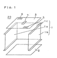
- FIG. 1 and Fig. 2 A perspective view for explaining the constitution of an embodiment of a high frequency heating cooking apparatus of the invention is shown in Fig. 1, and its front sectional view is given in Fig. 2.
- a heating compartment 20 for heating the food is composed of a nearly rectangular parallelepiped having a left side wall 1a, a right side wall 1b, a back side wall 4, a top panel 3, a bottom panel 4, and a door.
- a lower heater 11 is provided at the outside of the bottom panel 2, and an upper heater (not shown) at the outside of the top. panel 3.
- a magnetron 8 for generating high frequency electromagnetic waves, and a waveguide 15 are installed at the outside of the heating compartment 20 .
- the top panel 3 is manufactured from a stainless steel material. Stainless steel has a property of preventing from rusting and an excellent heat resistance.
- a power feed port 7, an intake hole 5, and an exhaust hole 6 are formed in the top panel 3.
- the waveguide 15 is installed between the power feed port 7 and magnetron 8.
- the high frequency electromagnetic waves generated by the magnetron 9 are guided into the heating compartment 20 through the waveguide 15 and power feed port 7.
- the intake hole 5 has plural tiny penetration holes, and plays the role of taking in the air for ventilating inside the heating compartment 20.
- the exhaust hole 6 has plural tiny penetration holes, and plays the role of exhausting the steam or gas in the heating compartment 20 to outside. It is preferred that the intake hole 5 is formed at a position remote from the exhaust hole 6.
- the intake hole 5, exhaust hole 6, and power feed port 7 are formed, for example, by blanking.
- the left side wall 1a, right side wall 1b, and back side wall 1c are integrally composed into a pi-form or a U-form. That is, the side wall 1 composed of the left side wall 1a, right side wall 1b, and back side wall 1c is an integral structure manufactured by folding and processing one plate material. Moreover, the left side wall 1a, right side wall 1b, and back side wall 1c do not have holes such as intake hole and exhaust hole.
- the side wall 1 composed of the left side wall 1a, right side wall 1b, and back side wall 1c is manufactured from a surface treated steel plate. The door is installed as the front side of the heating compartment so as to be opened and closed.
- the side wall 1 and bottom panel 2 are joined by welding, caulking or crimping.
- the side wall 1 and top panel 3 are joined by welding or crimping.
- the surface treated steel plate used in the side wall 1 composed of the left side wall 1a, right side wall 1b, and back side wall 1c is preferably a surface plated steel plate for preventing from rusting.
- the plated steel plate is not particularly limited, but, for example, an aluminum plated steel plate is used.
- the bottom panel 2 is manufactured from a stainless steel material.
- Stainless steel has an excellent heat resistance and a property of preventing from rusting.
- a protruding reducing portion 13 in a bead form is formed in the bottom panel 2 near the junction 9 of the side wall 1 and bottom plate 2, a protruding reducing portion 13 in a bead form is formed. If moisture released from the food in the heating compartment or water used when cleaning the inside of the heating compartment escapes from the junction 9, it is captured by the reducing portion 13, and is not propagated to the lower heater 11.
- the cooking material is put into the heating compartment 20, and the cooking material is heated and cooked by application of the magnetron 8 or heater 11.
- the air in the heating compartment 20 flows by convection in the heating compartment 20. and part of the air is discharged outside of the heating compartment 20 through the exhaust hole 6, while fresh air flows into the heating compartment 20.
- part of the steam generated from the cooking material is discharged outside of the heating compartment 20 through the exhaust port 6.
- the side wall 1 Since the side wall 1 is remote in distance from the lower heater 11 and upper heater, it is not heated to high temperature. Therefore, the plated steel plate used in the side wall 1 can sufficiently maintain its reliability in terms of temperature. Moreover, since the plated steel plate is generally less expensive than the stainless steel, the material cost of the side wall 1 is saved.
- rusting due to temperature and moisture is likely to occur in the cut section ends of the opening of the intake hole 5, exhaust hole 6, and power feed port 7.
- the intake hole 5, exhaust hole 6, and power feed power 7 are formed on the top panel which is made of stainless steel which prevents from rusting, rust is not formed.
- the side wall I made of plated steel plate does not have cut sections of penetration holes or opening, rust is not formed at the end face of holes. As a result, a rust-free heating compartment is obtained.
- a resin paint on the inner surface of the side wall.
- fluorine resin for example, fluorocarbon can be used.
- a painted steel plate of fluorine resin may be used on the surface of the steel plate.
- Application of fluorine resin on the steel plate is extremely easy. In this constitution, the same action and effect as mentioned above can be obtained.
Landscapes
- Physics & Mathematics (AREA)
- Electromagnetism (AREA)
- Engineering & Computer Science (AREA)
- Chemical & Material Sciences (AREA)
- Combustion & Propulsion (AREA)
- Mechanical Engineering (AREA)
- General Engineering & Computer Science (AREA)
- Electric Ovens (AREA)
Abstract
Description
- The present invention relates to a high frequency heating cooking apparatus with a heater or a microwave oven, and more particularly to the constitution of its heating compartment and method of manufacturing the same.
- A high frequency heating cooking apparatus according to the preamble of claim is known from JP-A-586397.
- The constitution of a heating compartment of a conventional high frequency heating cooking apparatus is described below while referring to Fig. 3and Fig. 4. A structural diagram of the heating compartment of the conventional high frequency heating cooking apparatus is shown in Fig. 3. A front sectional view of the conventional high frequency heating cOoking apparatus is given in Fig. 4. In Fig. 3 and Fig. 4, the heating compartment is composed of an assembly of a
left side wall 101, aright side wall 101, and anupper wall 103, abottom panel 102, and aback panel 104. Each member is joined by welding or crimping. Theside wall 101 is provided with apower feed port 107 for feeding high frequency electromagnetic waves generated by amagnetron 108 into the heating compartment, and anintake hole 105 for ventilation. Theback panel 104 is provided with anexhaust hole 106 for exhaust. The outer side of thebottom panel 102 is provided with a lower heater 111, and the outer side of theupper wall 103, with an upper heater 112. At the junction end of thebottom panel 102, there is aflange 110 for preventing the water escaping from ajunction 109 from propagating into the direction of the lower heater 111. - In such conventional constitution of the heating compartment, however, since the
upper wall 103 andbottom plate 102 in which the upper heater 112 and lower heater 111 are provided are exposed to high temperature, stainless steel materials of high heat resistance are needed. On the other hand, the right andleft side walls 101 are low in temperature, and do not need expensive stainless steel materials. In the conventional constitution, since theleft side wall 101,right side wall 101, andupper wall 103 are in an integral structure, stainless steel materials must be used, which resulted in a cost increase. - In the
side wall 101 andback panel 104, if plated steel plates other than stainless steel are used. rust is formed in theside wall 101 in other portions than the plated layers in the end portion of the holes of thepower feed port 107,intake hole 105, andexhaust hole 106. Another problem is the increase of material cost of theflange 110 for avoiding insulation failure by preventing water leak from thejunction 109 of theside wall 101 andbottom panel 102 from propagating into the lower heater 111. - It is hence an object of the invention to provide a high frequency heating cooking apparatus capable of preventing rusting, reducing cost, and insulating the heater easily.
- This is accomplished by the heater according to
claim 1 and the manufacturing method according toclaim 8. - Preferably, each one of the left side wall, the right side wall, and the back side wall does not have a cut section end portion of hole or opening.
- Preferably, the surface treated steel plate is a plated steel plate having a function of preventing from rusting.
- Preferably, the surface treated steel plate is an aluminum plated steel plate.
- Preferably, the surface treated steel plate is a painted steel plate.
- Preferably, the surface treated steel plate is a fluorine resin coated steel plate.
- Preferably, the top panel is formed of a stainless steel having a function for preventing from rusting.
- Preferably, the top panel forms an intake hole, an exhaust hole, and a power feed port for feeding the high frequency electric power into the heating compartment formed at specified positions.
- In the above constitution, the side wall of the heating compartment composed of left side wall, right side wall, and back side wall is a surface treated steel plate integrally formed in a pi-form or U-form. Hence, rusting is prevented, and the manufacturing cost is reduced at the same time. More particularly, notable effects are obtained when the surface treated steel plate aluminum plated steel plate or fluorine resin coated steel plate.
- Moreover, the top panel is formed of stainless steel, and penetration holes such as power feed opening, intake hole and exhaust hole are formed in the stainless steel, and the side wall made of steel plate does not have penetration hole. Accordingly, if inexpensive plated steel plate is used in the side wall, since it does not have cut section end portion of penetration hole or opening, the high frequency heating cooking apparatus preventing from rusting is obtained.
- Still more, the heater is installed outside of the top panel or bottom panel made of stainless steel, and is not installed at the side wall made of steel plate. Hence, if inexpensive plated steel plate is used in the side wall, the high frequency heating cooking apparatus highly reliable in heat resistance can be obtained. As a result, the manufacturing cost is lowered.
- In addition, the heater is installed at the lower side of the bottom plate, and a bead form reducing portion is formed near the end of the surface of inside of the bottom panel, which prevents water generated inside from passing through the junction part to contact with the heater. As a result, an excellent electric insulation of the heater is guaranteed.
-
- Fig. 1 is a perspective view for explaining the assembling constitution of a heating compartment of a high frequency heating cooking apparatus in an embodiment of the invention.
- Fig. 2 is a front sectional view of a high frequency heating cooking apparatus in an embodiment of the invention.
- Fig. 3 is a perspective view for explaining the assembling constitution of a heating compartment of a high frequency heating cooking apparatus in a prior art.
- Fig. 4 is a front sectional view of a high frequency heating cooking apparatus in a prior art.
-
- An embodiment of a high frequency heating cooking apparatus of the invention is described below while referring to Fig. 1 and Fig 2. A perspective view for explaining the constitution of an embodiment of a high frequency heating cooking apparatus of the invention is shown in Fig. 1, and its front sectional view is given in Fig. 2. In Fig. 1 and Fig. 2, a
heating compartment 20 for heating the food is composed of a nearly rectangular parallelepiped having a left side wall 1a, a right side wall 1b, a back side wall 4, atop panel 3, a bottom panel 4, and a door. A lower heater 11 is provided at the outside of thebottom panel 2, and an upper heater (not shown) at the outside of the top.panel 3. At the outside of theheating compartment 20, amagnetron 8 for generating high frequency electromagnetic waves, and a waveguide 15 are installed. - The
top panel 3 is manufactured from a stainless steel material. Stainless steel has a property of preventing from rusting and an excellent heat resistance. Apower feed port 7, anintake hole 5, and anexhaust hole 6 are formed in thetop panel 3. At the upper side of thetop panel 3, the waveguide 15 is installed between thepower feed port 7 andmagnetron 8. The high frequency electromagnetic waves generated by the magnetron 9 are guided into theheating compartment 20 through the waveguide 15 andpower feed port 7. Theintake hole 5 has plural tiny penetration holes, and plays the role of taking in the air for ventilating inside theheating compartment 20. Theexhaust hole 6 has plural tiny penetration holes, and plays the role of exhausting the steam or gas in theheating compartment 20 to outside. It is preferred that theintake hole 5 is formed at a position remote from theexhaust hole 6. Theintake hole 5,exhaust hole 6, andpower feed port 7 are formed, for example, by blanking. - The left side wall 1a, right side wall 1b, and back side wall 1c are integrally composed into a pi-form or a U-form. That is, the
side wall 1 composed of the left side wall 1a, right side wall 1b, and back side wall 1c is an integral structure manufactured by folding and processing one plate material. Moreover, the left side wall 1a, right side wall 1b, and back side wall 1c do not have holes such as intake hole and exhaust hole. Theside wall 1 composed of the left side wall 1a, right side wall 1b, and back side wall 1c is manufactured from a surface treated steel plate. The door is installed as the front side of the heating compartment so as to be opened and closed. - The
side wall 1 andbottom panel 2 are joined by welding, caulking or crimping. Theside wall 1 andtop panel 3 are joined by welding or crimping. - The surface treated steel plate used in the
side wall 1 composed of the left side wall 1a, right side wall 1b, and back side wall 1c is preferably a surface plated steel plate for preventing from rusting. The plated steel plate is not particularly limited, but, for example, an aluminum plated steel plate is used. - The
bottom panel 2 is manufactured from a stainless steel material. Stainless steel has an excellent heat resistance and a property of preventing from rusting. - In the
bottom panel 2 near the junction 9 of theside wall 1 andbottom plate 2, a protruding reducingportion 13 in a bead form is formed. If moisture released from the food in the heating compartment or water used when cleaning the inside of the heating compartment escapes from the junction 9, it is captured by the reducingportion 13, and is not propagated to the lower heater 11. - In this constitution, the cooking material is put into the
heating compartment 20, and the cooking material is heated and cooked by application of themagnetron 8 or heater 11. At this time, the air in theheating compartment 20 flows by convection in theheating compartment 20. and part of the air is discharged outside of theheating compartment 20 through theexhaust hole 6, while fresh air flows into theheating compartment 20. At this time, part of the steam generated from the cooking material is discharged outside of theheating compartment 20 through theexhaust port 6. - In this constitution, the following action and effect are obtained.
- Since the
side wall 1 is remote in distance from the lower heater 11 and upper heater, it is not heated to high temperature. Therefore, the plated steel plate used in theside wall 1 can sufficiently maintain its reliability in terms of temperature. Moreover, since the plated steel plate is generally less expensive than the stainless steel, the material cost of theside wall 1 is saved. - Generally speaking, rusting due to temperature and moisture is likely to occur in the cut section ends of the opening of the
intake hole 5,exhaust hole 6, andpower feed port 7. In this embodiment, however, since theintake hole 5,exhaust hole 6, andpower feed power 7 are formed on the top panel which is made of stainless steel which prevents from rusting, rust is not formed. Moreover, since the side wall I made of plated steel plate does not have cut sections of penetration holes or opening, rust is not formed at the end face of holes. As a result, a rust-free heating compartment is obtained. - By the constitution of forming the projecting reducing
portion 13 in thebottom panel 2 near the junction 9 of the side wall I andbottom panel 2, water in theheating compartment 20 is prevented from escaping from thebottom panel 2, so that the electric insulation of the lower heater 11 can be easily assured. - In the embodiment, to enhance prevention of contamination of the inner wall of the heating compartment, it is also possible to apply a resin paint on the inner surface of the side wall. As the fluorine resin, for example, fluorocarbon can be used. For instance, as the material for the
side wall 1, a painted steel plate of fluorine resin may be used on the surface of the steel plate. Application of fluorine resin on the steel plate is extremely easy. In this constitution, the same action and effect as mentioned above can be obtained. - Thus, in the high frequency cooking apparatus of the invention, it is not required to use an expensive stainless steel in the side wall, and an inexpensive plated steel plate can be used, while preventing from rusting on the hole end surface, so that the cost is reduced substantially.
- Besides, by forming a bead form reducing portion near the junction of the bottom panel of the heating compartment, water escaping from the junction is not propagated up to the heater, so that insulation of the heater can be assured in a simple constitution.
-
- 1
- Side wall
- 1a
- Left side wall
- 1b
- Right side wall
- 1d
- Back side wall
- 2
- Bottom panel
- 3
- Top panel
- 5
- Intake hole
- 6
- Exhaust hole
- 7
- Power feed port
- 8
- Magnetron
- 9
- Jonction
- 11
- Heater
- 13
- Bead form reducing portion
- 15
- Waveguide
- 20
- Heating compartment
Claims (13)
- A high frequency heating cooking apparatus comprising:wherein said heater is installed at said outside of at least one of said bottom panel and said top panel, anda heating compartment having a left side wall, a right side wall, back side wall, a bottom panel, and a top panel, for containing and heating food therein,a magnetron installed at an outside of said heating compartment, for generating a high frequency electric power,a duct for leading said high frequency electric power into said heating compartment, and said left side wall, said right side wall, and said back side wall are formed integrally of one plate, characterised in thata heater is installed at an outside of said heating compartment,
each of said left side wall, said right side wall, and said back side wall is a plated steel plate on the inner side and said plated steel plate has a function of preventing from rusting. - A high frequency heating cooking apparatus of claim 1, wherein said each of said left side wall, said right side wall, and said back side wall does not have a cut section end portion of hole or opening.
- A high frequency heating cooking apparatus of any preceding claim, wherein said plated steel plate is an aluminum plated steel plate.
- A high frequency heating cooking apparatus of any preceding claim, wherein said top panel is formed of a stainless steel having a function for preventing from rusting.
- A high frequency heating cooking apparatus of any preceding claim, wherein said top panel forms a penetration hole having functions of intake and exhaust formed at a specified position.
- A high frequency heating cooking apparatus of any preceding claim wherein said top panel forms an intake hole, an exhaust hole, and a power feed opening for feeding said high frequency electric power into said heating compartment formed at specified positions.
- A high frequency heating cooking apparatus of any preceding claim,
wherein each one of said left side wall, right side wall, and back side wall has a junction portion bonded to said bottom panel,
said heater is installed at the lower side of said bottom panel,
a bead form reducing portion is formed near the end of surface of the inner side of said bottom panel, and
flow of water generated inside of said heating compartment into said junction portion is arrested by said reducing portion. - A manufacturing method of a high frequency heating cooking apparatus according to one of claims 1-7 comprising:1) a step of manufacturing a heating compartment, having(a) a step of folding and processing one plated steel plate to form side walls having a left side wall, a right side wall, and a back side wall, wherein said steel plate is plated on the inner side,(b) a step of joining a top panel above said walls,(c) a step of joining a bottom panel below said side walls, and(d) a step of placing a door to be opened and closed, before said side walls,(2) a step of installing a magnetron for generating a high frequency electric power to an outside of said heating compartment,(3) a step of installing a duct for leading said high frequency electric power into said heating compartment, and(4) a step of installing a heater at an outside of said heating compartment; wherein said plated steel plate has a function of preventing rusting.
- A manufacturing method of high frequency heating cooking apparatus of claim 8, wherein said side walls do not have cut section end portion of hole or opening.
- A manufacturing method of high frequency heating cooking apparatus of claim 8 or 9, wherein said plated steel plate is an aluminum plated steel plate.
- A manufacturing method of high frequency heating cooking apparatus of claims 8, 9 or 10, wherein said top panel is formed of a stainless steel having a function for preventing from rusting.
- A manufacturing method of high frequency heating cooking apparatus of claim 8, 9, 10 or 11, wherein said top panel forms an intake hole, an exhaust hole, and a power feed opening for feeding said high frequency electric power into said heating compartment formed at specified positions.
- A manufacturing method of high frequency heating cooking apparatus of claim 8, 9, 10, 11 or 12,
wherein said heater is installed at the lower side of said bottom panel, a bead form reducing portion is formed near the end of surface of the inner side of said bottom panel, and
flow of water generated inside of said heating compartment into said junction portion is arrested by said reducing portion.
Applications Claiming Priority (4)
| Application Number | Priority Date | Filing Date | Title |
|---|---|---|---|
| JP138080/96 | 1996-05-31 | ||
| JP13808096 | 1996-05-31 | ||
| JP8138080A JPH09318066A (en) | 1996-05-31 | 1996-05-31 | High frequency heating cooker |
| PCT/JP1997/001722 WO1997045679A1 (en) | 1996-05-31 | 1997-05-21 | High-frequency cooker and method of manufacturing the same |
Publications (3)
| Publication Number | Publication Date |
|---|---|
| EP0905452A1 EP0905452A1 (en) | 1999-03-31 |
| EP0905452A4 EP0905452A4 (en) | 2000-03-15 |
| EP0905452B1 true EP0905452B1 (en) | 2003-12-10 |
Family
ID=15213498
Family Applications (1)
| Application Number | Title | Priority Date | Filing Date |
|---|---|---|---|
| EP97922136A Expired - Lifetime EP0905452B1 (en) | 1996-05-31 | 1997-05-21 | High-frequency cooker and method of manufacturing the same |
Country Status (7)
| Country | Link |
|---|---|
| US (1) | US6191403B1 (en) |
| EP (1) | EP0905452B1 (en) |
| JP (1) | JPH09318066A (en) |
| KR (1) | KR100433334B1 (en) |
| CN (1) | CN1129735C (en) |
| CA (1) | CA2257144C (en) |
| WO (1) | WO1997045679A1 (en) |
Cited By (2)
| Publication number | Priority date | Publication date | Assignee | Title |
|---|---|---|---|---|
| EP2295867A2 (en) | 2009-09-09 | 2011-03-16 | BSH Bosch und Siemens Hausgeräte GmbH | Gas range and gas stove with associated gas range |
| US8895902B2 (en) | 2010-03-17 | 2014-11-25 | Duke Manufacturing Co. | Oven for heating food |
Families Citing this family (2)
| Publication number | Priority date | Publication date | Assignee | Title |
|---|---|---|---|---|
| KR101411156B1 (en) * | 2007-11-29 | 2014-07-02 | 엘지전자 주식회사 | Cooking equipment |
| EP2547962A4 (en) * | 2010-03-17 | 2013-07-31 | Duke Mfg Co | OVEN FOR HEATING FOOD |
Family Cites Families (21)
| Publication number | Priority date | Publication date | Assignee | Title |
|---|---|---|---|---|
| JPS5638322Y2 (en) * | 1974-07-01 | 1981-09-08 | ||
| JPS516553A (en) | 1974-07-05 | 1976-01-20 | Fuji Photo Film Co Ltd | SHORYOEKIHOJUSOCHI |
| JPS5293952U (en) * | 1976-01-07 | 1977-07-13 | ||
| JPS5938726B2 (en) | 1976-02-02 | 1984-09-19 | 株式会社福井村田製作所 | Manufacturing method of columnar porcelain capacitor |
| JPS5850169Y2 (en) * | 1977-03-31 | 1983-11-15 | 松下電器産業株式会社 | High frequency heating device |
| JPS53135657A (en) | 1977-04-30 | 1978-11-27 | Minolta Camera Co Ltd | Eye lens in eyepiece system |
| JPS5563329A (en) * | 1978-11-01 | 1980-05-13 | Matsushita Electric Ind Co Ltd | Multi-function type heating cooker |
| JPS56149531A (en) * | 1980-04-22 | 1981-11-19 | Sharp Corp | Hot-air circulation type cooker |
| JPS5721722A (en) * | 1980-07-14 | 1982-02-04 | Mitsubishi Electric Corp | Manufacture of heating box |
| JPS586397A (en) | 1981-07-03 | 1983-01-13 | Matsushita Refrig Co | Heat exchanger due to brazing within furnace |
| JPS586397U (en) * | 1981-07-03 | 1983-01-17 | 松下電器産業株式会社 | High frequency heating device |
| JPS60155430A (en) | 1984-01-25 | 1985-08-15 | Kishimoto Akira | Method and apparatus for manufacturing welded can body with corrected weld part |
| JPS613302U (en) * | 1984-06-13 | 1986-01-10 | 三洋電機株式会社 | microwave oven |
| JPS613302A (en) | 1984-06-15 | 1986-01-09 | Hitachi Ltd | automatic tracking device |
| JPS60155430U (en) * | 1985-01-17 | 1985-10-16 | シャープ株式会社 | heating cooker |
| EP0198500B1 (en) * | 1985-04-17 | 1991-09-25 | Matsushita Electric Industrial Co., Ltd. | Heat cooking apparatus |
| JPS62110298A (en) * | 1985-11-08 | 1987-05-21 | 松下電器産業株式会社 | High frequency heating device |
| US4680439A (en) * | 1986-05-30 | 1987-07-14 | Litton Systems, Inc. | Plastic microwave oven cavity |
| JPH02306578A (en) * | 1989-05-19 | 1990-12-19 | Matsushita Electric Ind Co Ltd | How to clean the heating cooker and the dirt inside it |
| JP2614336B2 (en) * | 1989-11-24 | 1997-05-28 | 株式会社東芝 | High frequency cooking device |
| JPH04244518A (en) * | 1991-01-29 | 1992-09-01 | Matsushita Electric Ind Co Ltd | heating cooker |
-
1996
- 1996-05-31 JP JP8138080A patent/JPH09318066A/en active Pending
-
1997
- 1997-05-21 EP EP97922136A patent/EP0905452B1/en not_active Expired - Lifetime
- 1997-05-21 KR KR10-1998-0709673A patent/KR100433334B1/en not_active Expired - Fee Related
- 1997-05-21 WO PCT/JP1997/001722 patent/WO1997045679A1/en not_active Ceased
- 1997-05-21 CA CA002257144A patent/CA2257144C/en not_active Expired - Fee Related
- 1997-05-21 US US09/194,636 patent/US6191403B1/en not_active Expired - Fee Related
- 1997-05-21 CN CN97195114A patent/CN1129735C/en not_active Expired - Fee Related
Cited By (2)
| Publication number | Priority date | Publication date | Assignee | Title |
|---|---|---|---|---|
| EP2295867A2 (en) | 2009-09-09 | 2011-03-16 | BSH Bosch und Siemens Hausgeräte GmbH | Gas range and gas stove with associated gas range |
| US8895902B2 (en) | 2010-03-17 | 2014-11-25 | Duke Manufacturing Co. | Oven for heating food |
Also Published As
| Publication number | Publication date |
|---|---|
| CN1129735C (en) | 2003-12-03 |
| EP0905452A4 (en) | 2000-03-15 |
| US6191403B1 (en) | 2001-02-20 |
| KR20000016106A (en) | 2000-03-25 |
| HK1021017A1 (en) | 2000-05-26 |
| WO1997045679A1 (en) | 1997-12-04 |
| CN1220728A (en) | 1999-06-23 |
| EP0905452A1 (en) | 1999-03-31 |
| CA2257144A1 (en) | 1997-12-04 |
| KR100433334B1 (en) | 2004-08-16 |
| CA2257144C (en) | 2005-04-12 |
| JPH09318066A (en) | 1997-12-12 |
Similar Documents
| Publication | Publication Date | Title |
|---|---|---|
| KR100233437B1 (en) | Door of a microwave oven | |
| CA1163682A (en) | Microwave oven feed system | |
| CA1202374A (en) | High-frequency heating device | |
| KR20040052325A (en) | Wall mounting type microwave oven | |
| US6191403B1 (en) | High frequency heating cooking apparatus and manufacturing method thereof | |
| GB2126060A (en) | High-frequency heating apparatus | |
| CN1184919A (en) | Micro-wave oven | |
| US4449025A (en) | Door seal construction for high frequency heating appliance | |
| US4114013A (en) | Choke for combined microwave and self-cleaning oven | |
| EP0131324A2 (en) | A method of manufacturing doors for domestic ovens combining microwave and electrical resistance heating | |
| EP0584933B1 (en) | Heating apparatus enclosed in a cabinet during its use | |
| EP0374520A1 (en) | A microwave oven optionally also having thermal operation | |
| KR100551489B1 (en) | Wall-mounted Microwave | |
| KR200238113Y1 (en) | Connector assembly structure of microwave oven | |
| KR20000006061U (en) | microwave | |
| WO2026041894A1 (en) | Cooking appliance | |
| HK1021017B (en) | High-frequency cooker and method of manufacturing the same | |
| CN121774370A (en) | Cooking equipment | |
| KR100259374B1 (en) | Convection Assembly for Microwave Oven | |
| JPH10169995A (en) | Cooker | |
| KR19990023521U (en) | Microwave Intake Device | |
| KR100261483B1 (en) | Microwave cabinet | |
| KR20000033478A (en) | Microwave easy to block leakage | |
| KR100936154B1 (en) | Microwave | |
| JPH0319450B2 (en) |
Legal Events
| Date | Code | Title | Description |
|---|---|---|---|
| PUAI | Public reference made under article 153(3) epc to a published international application that has entered the european phase |
Free format text: ORIGINAL CODE: 0009012 |
|
| 17P | Request for examination filed |
Effective date: 19981030 |
|
| AK | Designated contracting states |
Kind code of ref document: A1 Designated state(s): GB |
|
| A4 | Supplementary search report drawn up and despatched |
Effective date: 20000127 |
|
| AK | Designated contracting states |
Kind code of ref document: A4 Designated state(s): GB |
|
| RIC1 | Information provided on ipc code assigned before grant |
Free format text: 7F 24C 7/02 A, 7H 05B 6/64 B, 7H 05B 6/80 B |
|
| 17Q | First examination report despatched |
Effective date: 20020315 |
|
| GRAH | Despatch of communication of intention to grant a patent |
Free format text: ORIGINAL CODE: EPIDOS IGRA |
|
| GRAS | Grant fee paid |
Free format text: ORIGINAL CODE: EPIDOSNIGR3 |
|
| GRAA | (expected) grant |
Free format text: ORIGINAL CODE: 0009210 |
|
| AK | Designated contracting states |
Kind code of ref document: B1 Designated state(s): GB |
|
| REG | Reference to a national code |
Ref country code: GB Ref legal event code: FG4D |
|
| PLBE | No opposition filed within time limit |
Free format text: ORIGINAL CODE: 0009261 |
|
| STAA | Information on the status of an ep patent application or granted ep patent |
Free format text: STATUS: NO OPPOSITION FILED WITHIN TIME LIMIT |
|
| 26N | No opposition filed |
Effective date: 20040913 |
|
| PGFP | Annual fee paid to national office [announced via postgrant information from national office to epo] |
Ref country code: GB Payment date: 20150520 Year of fee payment: 19 |
|
| GBPC | Gb: european patent ceased through non-payment of renewal fee |
Effective date: 20160521 |
|
| PG25 | Lapsed in a contracting state [announced via postgrant information from national office to epo] |
Ref country code: GB Free format text: LAPSE BECAUSE OF NON-PAYMENT OF DUE FEES Effective date: 20160521 |