EP0905573A2 - Paper conditioning apparatus - Google Patents
Paper conditioning apparatus Download PDFInfo
- Publication number
- EP0905573A2 EP0905573A2 EP98307478A EP98307478A EP0905573A2 EP 0905573 A2 EP0905573 A2 EP 0905573A2 EP 98307478 A EP98307478 A EP 98307478A EP 98307478 A EP98307478 A EP 98307478A EP 0905573 A2 EP0905573 A2 EP 0905573A2
- Authority
- EP
- European Patent Office
- Prior art keywords
- rolls
- moisturizing
- pair
- metering
- paper
- Prior art date
- Legal status (The legal status is an assumption and is not a legal conclusion. Google has not performed a legal analysis and makes no representation as to the accuracy of the status listed.)
- Granted
Links
Images

Classifications
-
- B—PERFORMING OPERATIONS; TRANSPORTING
- B65—CONVEYING; PACKING; STORING; HANDLING THIN OR FILAMENTARY MATERIAL
- B65H—HANDLING THIN OR FILAMENTARY MATERIAL, e.g. SHEETS, WEBS, CABLES
- B65H37/00—Article or web delivery apparatus incorporating devices for performing specified auxiliary operations
-
- B—PERFORMING OPERATIONS; TRANSPORTING
- B65—CONVEYING; PACKING; STORING; HANDLING THIN OR FILAMENTARY MATERIAL
- B65H—HANDLING THIN OR FILAMENTARY MATERIAL, e.g. SHEETS, WEBS, CABLES
- B65H29/00—Delivering or advancing articles from machines; Advancing articles to or into piles
- B65H29/12—Delivering or advancing articles from machines; Advancing articles to or into piles by means of the nip between two, or between two sets of, moving tapes or bands or rollers
-
- G—PHYSICS
- G03—PHOTOGRAPHY; CINEMATOGRAPHY; ANALOGOUS TECHNIQUES USING WAVES OTHER THAN OPTICAL WAVES; ELECTROGRAPHY; HOLOGRAPHY
- G03G—ELECTROGRAPHY; ELECTROPHOTOGRAPHY; MAGNETOGRAPHY
- G03G15/00—Apparatus for electrographic processes using a charge pattern
- G03G15/65—Apparatus which relate to the handling of copy material
- G03G15/6555—Handling of sheet copy material taking place in a specific part of the copy material feeding path
- G03G15/6573—Feeding path after the fixing point and up to the discharge tray or the finisher, e.g. special treatment of copy material to compensate for effects from the fixing
-
- B—PERFORMING OPERATIONS; TRANSPORTING
- B05—SPRAYING OR ATOMISING IN GENERAL; APPLYING FLUENT MATERIALS TO SURFACES, IN GENERAL
- B05C—APPARATUS FOR APPLYING FLUENT MATERIALS TO SURFACES, IN GENERAL
- B05C1/00—Apparatus in which liquid or other fluent material is applied to the surface of the work by contact with a member carrying the liquid or other fluent material, e.g. a porous member loaded with a liquid to be applied as a coating
- B05C1/04—Apparatus in which liquid or other fluent material is applied to the surface of the work by contact with a member carrying the liquid or other fluent material, e.g. a porous member loaded with a liquid to be applied as a coating for applying liquid or other fluent material to work of indefinite length
- B05C1/08—Apparatus in which liquid or other fluent material is applied to the surface of the work by contact with a member carrying the liquid or other fluent material, e.g. a porous member loaded with a liquid to be applied as a coating for applying liquid or other fluent material to work of indefinite length using a roller or other rotating member which contacts the work along a generating line
- B05C1/0826—Apparatus in which liquid or other fluent material is applied to the surface of the work by contact with a member carrying the liquid or other fluent material, e.g. a porous member loaded with a liquid to be applied as a coating for applying liquid or other fluent material to work of indefinite length using a roller or other rotating member which contacts the work along a generating line the work being a web or sheets
- B05C1/0834—Apparatus in which liquid or other fluent material is applied to the surface of the work by contact with a member carrying the liquid or other fluent material, e.g. a porous member loaded with a liquid to be applied as a coating for applying liquid or other fluent material to work of indefinite length using a roller or other rotating member which contacts the work along a generating line the work being a web or sheets the coating roller co-operating with other rollers, e.g. dosing, transfer rollers
-
- B—PERFORMING OPERATIONS; TRANSPORTING
- B05—SPRAYING OR ATOMISING IN GENERAL; APPLYING FLUENT MATERIALS TO SURFACES, IN GENERAL
- B05C—APPARATUS FOR APPLYING FLUENT MATERIALS TO SURFACES, IN GENERAL
- B05C9/00—Apparatus or plant for applying liquid or other fluent material to surfaces by means not covered by any preceding group, or in which the means of applying the liquid or other fluent material is not important
- B05C9/04—Apparatus or plant for applying liquid or other fluent material to surfaces by means not covered by any preceding group, or in which the means of applying the liquid or other fluent material is not important for applying liquid or other fluent material to opposite sides of the work
-
- B—PERFORMING OPERATIONS; TRANSPORTING
- B65—CONVEYING; PACKING; STORING; HANDLING THIN OR FILAMENTARY MATERIAL
- B65H—HANDLING THIN OR FILAMENTARY MATERIAL, e.g. SHEETS, WEBS, CABLES
- B65H2301/00—Handling processes for sheets or webs
- B65H2301/50—Auxiliary process performed during handling process
- B65H2301/51—Modifying a characteristic of handled material
- B65H2301/514—Modifying physical properties
- B65H2301/5142—Moistening
-
- G—PHYSICS
- G03—PHOTOGRAPHY; CINEMATOGRAPHY; ANALOGOUS TECHNIQUES USING WAVES OTHER THAN OPTICAL WAVES; ELECTROGRAPHY; HOLOGRAPHY
- G03G—ELECTROGRAPHY; ELECTROPHOTOGRAPHY; MAGNETOGRAPHY
- G03G2215/00—Apparatus for electrophotographic processes
- G03G2215/00362—Apparatus for electrophotographic processes relating to the copy medium handling
- G03G2215/00535—Stable handling of copy medium
- G03G2215/0067—Damping device
Definitions
- This invention relates generally to a substrate conditioning system for an electrophotographic printing machine and, more particularly, concerns a system for metering and applying moisture to cut sheets or web material in a full color process printing machine.
- an architecture which comprises a plurality of image forming stations.
- One example of the plural image forming station architecture utilizes an image-on-image (IOI) system in which the photoreceptive member is recharged, reimaged and developed for each color separation.
- IIOI image-on-image
- This charging, imaging, developing and recharging, reimaging and developing, all followed by transfer to paper, is done in a single revolution of the photoreceptor in so-called single pass machines, while multipass architectures form each color separation with a single charge, image and develop, with separate transfer operations for each color.
- the single pass architecture offers a potential for high throughput.
- Paper curl is defined as any deviation from it's flat state. In the xerographic process, fusing drives moisture out. When regaining moisture from the environment, paper experiences curl due to differential hygroexpansitivity and thermalexpansitivity, between the paper and toner, as well as, the dimensional instability of paper due to it's moisture history. The paper expands due to moisture reabsorption, but the toner does not expand, thus developing curl. Paper curl is one of the primary causes for paper handling problems in copying machines. Problems, such as, stubbing, image deletions and improper stacking result from copy sheet curl. These problems are more severe for color copies than black and white due to differences in their toner mass area, substrates, and fuser characteristics.
- US-A-5,264,899 describes a system for adding moisture to a copy sheet.
- the toner fixation step of electrostatographic reproduction desiccates paper, which may lead to the formation of a wave along the sheet edge.
- US-A-5,434,029 describes an apparatus and method of preventing the curling of a substrate having toner images electrostatically adhered thereto which substrate has been subjected to heat for the purpose of fixing the toner images to the substrate. Simultaneous constraint of the copy substrate and the application of moisture thereto is effected by passing the substrate through the nip formed by two pressure engaged rollers, one of which is utilized for applying the water to the back side of the substrate as the substrate passes through the aforementioned nip.
- an apparatus for re-moisturizing sheets immediately after fusing to rapidly bring the sheets to temperature and moisture equilibrium comprises: a pair of troughs for storing a quantity of liquid; a pair of wicks with one each of said pair of wicks being positioned within one each of said pair of troughs; a soaker hose for wetting said wicks by supplying liquid to said troughs; a pair of generally cylindrical moisturizing rolls, each having an outer cylindrical surface, said moisturizing rolls being aligned with respect to one another along their axes so as to define a nip between said outer cylindrical surfaces when a sheet is present therebetween; a plurality of donor rolls with one each of said plurality of donor rolls being in contact with each of said pair of moisturizing rolls; a pair of metering rolls positioned in circumferential surface contact with a pair of said plurality of said donor rolls for supplying liquid from said troughs to said pair of moisturizing rolls; and a pair of metering blade
- This embodiment relates to an imaging system which is used to produce color output in a single revolution or pass of a photoreceptor belt but the conditioning system is also useable with a multiple pass color process system, a single or multiple pass highlight color system and a black and white printing system.
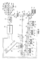
- the printing machine of the present invention uses a charge retentive surface in the form of an Active Matrix (AMAT) photoreceptor belt 10 supported for movement in the direction indicated by arrow 12, for advancing sequentially through the various xerographic process stations.
- the belt is entrained about a drive roller 14, tension roller 16 and fixed roller 18 and the roller 14 is operatively connected to a drive motor 20 for effecting movement of the belt through the xerographic stations.
- AMAT Active Matrix
- a portion of belt 10 passes through charging station A where a corona generating device, indicated generally by the reference numeral 22, charges the photoconductive surface of belt 10 to a relatively high, substantially uniform, preferably negative potential.
- a controller receives the image signals representing the desired output image and processes these signals to convert them to the various color separations of the image which is transmitted to a laser based output scanning device 24 which causes the charge retentive surface to be discharged in accordance with the output from the scanning device.
- the scanning device is a laser Raster Output Scanner (ROS) .
- ROS Raster Output Scanner
- the ROS could be replaced by other xerographic exposure devices such as LED arrays.
- the photoreceptor which is initially charged to a voltage V 0 , undergoes dark decay to a level V ddp equal to about -500 volts. When exposed at the exposure station B it is discharged to V expose equal to about -50 volts. Thus after exposure, the photoreceptor contains a monopolar voltage profile of high and low voltages, the former corresponding to charged areas and the latter corresponding to discharged or background areas.
- the development roll As a first development station C which contains black toner 35, developer structure, indicated generally by the reference numeral 42 utilizing a hybrid jumping development (HJD) system, the development roll, better known as the donor roll, is powered by two development fields (potentials across an air gap).
- the first field is the ac jumping field which is used for toner cloud generation.
- the second field is the dc development field which is used to control the amount of developed toner mass on the photoreceptor.
- the toner cloud causes charged toner particles to be attracted to the electrostatic latent image. Appropriate developer biasing is accomplished via a power supply.
- This type of system is a non-contact type in which only toner particles 35 (black, for example) are attracted to the latent image and there is no mechanical contact between the photoreceptor and a toner delivery device to disturb a previously developed, but unfixed, image.
- a corona recharge device 36 having a high output current vs. control surface voltage (I/V) characteristic slope is employed for raising the voltage level of both the toned and untoned areas on the photoreceptor to a substantially uniform level.
- the recharging device 36 serves to recharge the photoreceptor to a predetermined level.
- a second exposure/imaging device 38 which comprises a laser based output structure is utilized for selectively discharging the photoreceptor on toned areas and/or bare areas, pursuant to the image to be developed with the second color toner.
- the photoreceptor contains toned and untoned areas at relatively high voltage levels and toned and untoned areas at relatively low voltage levels. These low voltage areas represent image areas which are developed using discharged area development (DAD).
- DAD discharged area development
- a negatively charged, developer material 40 comprising color toner is employed.
- the toner which by way of example may be yellow, is contained in a developer housing structure 42 disposed at a second developer station D and is presented to the latent images on the photoreceptor by way of a second HSD developer system.
- a power supply (not shown) serves to electrically bias the developer structure to a level effective to develop the discharged image areas with negatively charged yellow toner particles 40.
- a negative pre-transfer dicorotron member 50 is provided to condition the toner for effective transfer to a substrate using positive corona discharge.
- a sheet of support material 52 is moved into contact with the toner images at transfer station G.
- the sheet of support material is advanced to transfer station G by conventional sheet feeding apparatus, not shown.
- the sheet feeding apparatus includes a feed roll contacting the uppermost sheet of a stack copy sheets in trays.
- the feed rolls rotate so as to advance the uppermost sheet from stack into a chute which directs the advancing sheet of support material into contact with photoconductive surface of belt 10 in a timed sequence so that the toner powder image developed thereon contacts the advancing sheet of support material at transfer station G.
- Transfer station G includes a transfer dicorotron 54 which sprays positive ions onto the backside of sheet 52. This attracts the negatively charged toner powder images from the belt 10 to sheet 52.
- a detack dicorotron 56 is provided for facilitating stripping of the sheets from the belt 10.
- Fusing station H includes a fuser assembly, indicated generally by the reference numeral 60, which permanently affixes the transferred powder image to sheet 52.
- fuser assembly 60 comprises a heated fuser roller 62 and a backup or pressure roller 64.
- Sheet 52 passes between fuser roller 62 and backup roller 64 with the toner powder image contacting fuser roller 62. In this manner, the toner powder images are permanently affixed to sheet 52.
- a chute guides the advancing sheets 52 to sheet moisture replacement system 100 and then to a catch tray, not shown, for subsequent removal from the printing machine by the operator.
- the residual toner particles carried by the non-image areas on the photoconductive surface are removed therefrom. These particles are removed at cleaning station I using a cleaning brush structure contained in a housing 66.
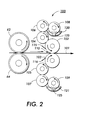
- the sheet conditioning device generally referred to as reference numeral 100, has hydrophilic moisturizing rollers 102, 103 which are rotated in a counter clockwise direction for 102 and a clockwise direction for 103 to receive the lead edge of incoming sheets 52 into the nip area 110.
- the conditioning agent in this case mostly water to which a surfactant can be added, is distributed to the moisturizing roll 102 from trough 120 and moisturizing 103 from trough 121, by way of metering rolls 108, 109.
- Troughs 120 and 121 each include a high density, cotton wick 125 to transfer a conditioning agent from supply trough 120 and 121 to metering rolls 108 and 109.
- the conditioning agent is applied onto the metering rolls and then transfers to donor rolls 106, 104 and donor rolls 107 and 105 from metering roll 109 and then to moisturizing rolls 102 and 103. Simply imersing part of each metering roll in a trough of water will not sufficiently wet it's surface.
- the agent does not stick to the rotating metering roll surface.
- high density wick 125 is added to each trough.
- the wick is kept in close contact with the textured metering roll.
- the amount of moisture added to a sheet is a function of the pressure between the sheet 52 and the moisturizing rolls 102, 103. The direction of the sheet is indicated by arrow 101.
- Moisturizing rolls 102 and 103 are textured to hold conditioning agent by capillary action. Excess conditioning agent applied to the moisturizing rolls must be removed. If left on the surface of the moisturizing rolls, it cannot penetrate the moisturizing nip 110 and will form a bead at the nip input. When a sheet enters, the agent will overmoisturize the lead edge resulting in excessive lead edge curl. Hence, metering blades 115 and 116 are included adjacent the outer cylindrical surface of moisturizing rolls 102 and 103, respectively. With blades 115 and 116 pressing against moisturizing rolls 102 and 103, respectively, beads of conditioning agent do not at the nip entrance.
- each blade is backed up by a piece of shim stock, for example, a 0.025" piece of plastic to give some rigidity to the blades.
- the blades are preferably 0.110" thick x 20 mm wide and positioned at an angle of approximately 45° with respect to a horizontal plane through the center of each of the moisturizing rolls.
- the blades are shown as wiper blades, but they may also operate as doctor blades.
- upper trough 120 and lower trough 121 are shown supplying conditioning agent to metering rolls 108 and 109, respectively.
- the troughs are supplied with conditioning agent from container 130 via a pump 140 and plumbing lines in the form of soaker hoses 150.
- metering rolls 108 and 109 are in contact with wicks 125 and to keep the wicks from being wetter on the end where the conditioning agent comes into the trough, a thin hose 150 containing multiple pin-holes 151 is positioned under each wick. The conditioning agent leaches out from the pin holes and uniformly wets the wicks.
- conditioning agent return tube 131 Overflow of conditioning agent from upper trough 120 exits through conditioning agent return tube 131 as does excess conditioning agent removed from the surfaces of moisturizing roll 102 at upper blade return 134 and from the surface of moisturizing roll 103 at lower blade return 135. Excess conditioning agent within lower trough 121 also exits through return tube 131 that is connected to empty into conditioning agent container 130.
- a paper conditioner adds a small amount of water to sheets in order to control sheet curl.
- the paper conditioner has plumbing that includes a pump, supply lines, overflow lines, metering blade lines and return lines.
- a soaker hose is used to uniformly distribute conditioner agent to a wick.
- the soaker hose has pin-holes that are evenly spaced adjacent the wick.
- the wick is a high density material, such as, cotton that contacts and supplies the conditioner agent to metering rolls. These rolls contact donor rolls, which contact moisturizing rolls which contact the paper. Metering blades are used to remove excess conditioning agent from the moisturizing rolls.
Landscapes
- Engineering & Computer Science (AREA)
- Mechanical Engineering (AREA)
- Physics & Mathematics (AREA)
- General Physics & Mathematics (AREA)
- Fixing For Electrophotography (AREA)
- Color Electrophotography (AREA)
- Paper (AREA)
- Control Or Security For Electrophotography (AREA)
Abstract
Description
Claims (10)
- An apparatus for re-moisturizing sheets immediately after fusing rapidly to bring the sheets to temperature and moisture equilibrium, comprising:a pair of troughs (121) for storing a quantity of liquid;a pair of wicks (125) one positioned in each trough (121);a soaker hose (150) for wetting said wicks (125) by supplying liquid to said troughs (121);a pair of generally cylindrical moisturizing rolls (102,103), each having an outer cylindrical surface, said moisturizing rolls (102,102) being aligned with respect to one another along their axes so as to define a nip (110) between them;a plurality of donor rolls (104,105,106,107) each of said pair of moisturizing rolls (102,103) having at least one donor roll (104,105) in contact with it;a pair of metering rolls (108,109) positioned in circumferential surface contact with a two of said plurality of said donor rolls (106,107) for supplying liquid from said wicks and troughs (121) to said pair of moisturizing rolls (102,103); and,a pair of wiper blades (115,116) each being positioned against said outer cylindrical surface of its respective one of said pair of moisturizing rolls (102,103) to remove excess liquid from said outer cylindrical surface of said moisturizing rolls.
- An apparatus according to claim 1, wherein said soaker hose (150) has pin-holes therein.
- An apparatus according to claim 1 or 2, wherein said wick (125) is made of high density cotton.
- An apparatus according to any one of the preceding claims, wherein one of said moisturizing rolls (102) rotates in a counter clockwise direction.
- An apparatus according to any one of the preceding claims, wherein said metering blades (115,116) are positioned on said outer cylindrical surfaces of said moisturizing rolls (102,103) at a 45° angle with respect to a horizontal plane through each of said moisturizing rolls.
- An apparatus according to any one of the preceding claims, wherein one of said metering rolls (108) rotates in a clockwise direction.
- An apparatus according to any one of the preceding claims, wherein said moisturizing rolls (102,103) are hydrophilic.
- An apparatus according to any one of the preceding claims, wherein said plurality of donor rolls comprise two pairs of rolls (104,105,106,107).
- An apparatus according to any one of the preceding claims, further comprising:the soaker hose (150) is connected to said conditioning agent source (130) for supplying conditioning agent to said troughs (121);
- A system for fixing a toner image to a copy sheet in an electrophotographic system so as to avoid the formation of copy sheet curl, comprising:first and second fusing rollers (62,64) defining a nip therebetween, at least one of said fusing rollers (62,64) being heated, wherein the fusing rollers serve to fix a toner image on a copy sheet through the application of heat and pressure to the copy sheet; anda conditioning apparatus in accordance with any one of the preceding claims for receiving a copy sheet from said fusing rollers (62,64).
Applications Claiming Priority (2)
| Application Number | Priority Date | Filing Date | Title |
|---|---|---|---|
| US08/939,896 US5987301A (en) | 1997-09-29 | 1997-09-29 | Paper conditioning system |
| US939896 | 1997-09-29 |
Publications (3)
| Publication Number | Publication Date |
|---|---|
| EP0905573A2 true EP0905573A2 (en) | 1999-03-31 |
| EP0905573A3 EP0905573A3 (en) | 2000-06-07 |
| EP0905573B1 EP0905573B1 (en) | 2003-08-13 |
Family
ID=25473903
Family Applications (1)
| Application Number | Title | Priority Date | Filing Date |
|---|---|---|---|
| EP98307478A Expired - Lifetime EP0905573B1 (en) | 1997-09-29 | 1998-09-15 | Paper conditioning apparatus |
Country Status (4)
| Country | Link |
|---|---|
| US (1) | US5987301A (en) |
| EP (1) | EP0905573B1 (en) |
| JP (1) | JPH11161107A (en) |
| DE (1) | DE69817113T2 (en) |
Cited By (2)
| Publication number | Priority date | Publication date | Assignee | Title |
|---|---|---|---|---|
| WO2008025742A1 (en) * | 2006-08-28 | 2008-03-06 | OCé PRINTING SYSTEMS GMBH | Device and method for post-machining printed carrier material by means of an electrographic printing or copying device |
| CN109622295A (en) * | 2018-12-19 | 2019-04-16 | 芜湖恒美电热器具有限公司 | Generate heat the automatic brush coating device of wicking surface |
Families Citing this family (15)
| Publication number | Priority date | Publication date | Assignee | Title |
|---|---|---|---|---|
| DE3826729A1 (en) * | 1988-08-05 | 1990-02-15 | Krauss Maffei Ag | METHOD FOR THE HEAT TREATMENT OF A HIGH-ALLOYED CHROMA STEEL |
| US6342445B1 (en) * | 2000-05-15 | 2002-01-29 | Micron Technology, Inc. | Method for fabricating an SrRuO3 film |
| US6363238B1 (en) | 2000-12-21 | 2002-03-26 | Xerox Corporation | Substrate conditioner seal using differential air pressure |
| US6801746B2 (en) * | 2001-08-08 | 2004-10-05 | Eastman Kodak Company | Method and system for reducing toner rub-off in an electrophotographic apparatus by using printers' anti-offset spray powder |
| JP2006008282A (en) * | 2004-06-23 | 2006-01-12 | Konica Minolta Business Technologies Inc | Paper sheet humidifier and image forming device |
| JP2007286151A (en) * | 2006-04-13 | 2007-11-01 | Konica Minolta Business Technologies Inc | Form humidification device and imaging system |
| JP4301280B2 (en) * | 2006-10-13 | 2009-07-22 | コニカミノルタビジネステクノロジーズ株式会社 | Paper humidifier and image forming apparatus provided with the same |
| JP2009109720A (en) * | 2007-10-30 | 2009-05-21 | Konica Minolta Business Technologies Inc | Paper humidifier and image forming apparatus with the same |
| JP2009220895A (en) * | 2008-03-13 | 2009-10-01 | Konica Minolta Business Technologies Inc | Sheet humidifying device and image forming system |
| JP4492721B2 (en) * | 2008-03-14 | 2010-06-30 | コニカミノルタビジネステクノロジーズ株式会社 | Paper coloring apparatus and image forming system |
| US8038280B2 (en) * | 2008-04-09 | 2011-10-18 | Xerox Corporation | Ink-jet printer and method for decurling cut sheet media prior to ink-jet printing |
| JP5152326B2 (en) * | 2008-09-19 | 2013-02-27 | コニカミノルタビジネステクノロジーズ株式会社 | Paper humidifier and image forming system |
| JP6165190B2 (en) * | 2014-04-30 | 2017-07-19 | キヤノン株式会社 | Sheet conveying apparatus and image forming apparatus |
| JP6344280B2 (en) * | 2015-03-26 | 2018-06-20 | コニカミノルタ株式会社 | Recording medium processing apparatus, image forming apparatus, and image forming system |
| JP6164251B2 (en) * | 2015-06-02 | 2017-07-19 | コニカミノルタ株式会社 | Paper humidifier and image forming system |
Family Cites Families (6)
| Publication number | Priority date | Publication date | Assignee | Title |
|---|---|---|---|---|
| US4198446A (en) * | 1978-02-14 | 1980-04-15 | Ncr Corporation | Apparatus for the manufacture of a dual coated manifold sheet with pressure-rupturable materials |
| US5434029A (en) * | 1991-05-06 | 1995-07-18 | Xerox Corporation | Curl prevention method for high TMA color copiers |
| US5264899A (en) * | 1992-10-21 | 1993-11-23 | Xerox Corporation | Sheet moisture replacement system using porous rolls |
| US5842105A (en) * | 1997-09-29 | 1998-11-24 | Xerox Corporation | Controlled moisturization of paper to eliminate curl |
| US5832359A (en) * | 1997-09-29 | 1998-11-03 | Xerox Corporation | Apparatus and method for sensing water film thickness on conditioner rolls |
| US5895154A (en) * | 1998-06-15 | 1999-04-20 | Xerox Corporation | Textured rollers for paper conditioning |
-
1997
- 1997-09-29 US US08/939,896 patent/US5987301A/en not_active Expired - Lifetime
-
1998
- 1998-09-15 EP EP98307478A patent/EP0905573B1/en not_active Expired - Lifetime
- 1998-09-15 DE DE69817113T patent/DE69817113T2/en not_active Expired - Lifetime
- 1998-09-21 JP JP10266414A patent/JPH11161107A/en not_active Withdrawn
Cited By (2)
| Publication number | Priority date | Publication date | Assignee | Title |
|---|---|---|---|---|
| WO2008025742A1 (en) * | 2006-08-28 | 2008-03-06 | OCé PRINTING SYSTEMS GMBH | Device and method for post-machining printed carrier material by means of an electrographic printing or copying device |
| CN109622295A (en) * | 2018-12-19 | 2019-04-16 | 芜湖恒美电热器具有限公司 | Generate heat the automatic brush coating device of wicking surface |
Also Published As
| Publication number | Publication date |
|---|---|
| US5987301A (en) | 1999-11-16 |
| EP0905573A3 (en) | 2000-06-07 |
| JPH11161107A (en) | 1999-06-18 |
| EP0905573B1 (en) | 2003-08-13 |
| DE69817113D1 (en) | 2003-09-18 |
| DE69817113T2 (en) | 2004-07-22 |
Similar Documents
| Publication | Publication Date | Title |
|---|---|---|
| EP0905573B1 (en) | Paper conditioning apparatus | |
| EP0905574B1 (en) | Controlled moisturization of paper to eliminate curl | |
| US5850589A (en) | Sheet moisture replacement system using water jet technology | |
| EP0905575B1 (en) | Apparatus for adjusting conditioner rolls | |
| US5970300A (en) | Apparatus for applying scents to paper in a printer/copier | |
| US5895154A (en) | Textured rollers for paper conditioning | |
| US6052553A (en) | Post-fusing sheet conditioning apparatus | |
| EP1288736A2 (en) | Multi-function air knife | |
| EP1293845B1 (en) | Composite blade for assisting complete transfer of a toner image from a photosensitive surface | |
| EP0862091B1 (en) | Device and system for conditioning a copy sheet | |
| US8064813B2 (en) | Fuser apparatus having fuser cleaner web and corresponding methods | |
| US5920751A (en) | Apparatus and method for controlling moisture and cooling rate for paper curl reduction | |
| US20090297186A1 (en) | Fuser apparatus having fuser cleaner web and corresponding methods | |
| US5930578A (en) | Moisturizing rolls with end grooves for eliminating water spill from their ends | |
| US5832359A (en) | Apparatus and method for sensing water film thickness on conditioner rolls | |
| US6249667B1 (en) | Conditioner rolls end seals | |
| EP1291736A2 (en) | Air knife for corrugating paper sheets | |
| US7796907B2 (en) | Method and apparatus for detecting and avoiding a defect on a fuser web | |
| US6363238B1 (en) | Substrate conditioner seal using differential air pressure | |
| JPH05333722A (en) | Image forming device | |
| JPH0980937A (en) | Transfer device for image forming device | |
| JPH0511642A (en) | Transfer device | |
| MXPA98000678A (en) | Paper conditioner with transfer rollers / articulan backrest | |
| JP2004151211A (en) | Electrophotographic double-sided simultaneous image forming device | |
| JPH11167315A (en) | Image forming device |
Legal Events
| Date | Code | Title | Description |
|---|---|---|---|
| PUAI | Public reference made under article 153(3) epc to a published international application that has entered the european phase |
Free format text: ORIGINAL CODE: 0009012 |
|
| AK | Designated contracting states |
Kind code of ref document: A2 Designated state(s): DE FR GB |
|
| AX | Request for extension of the european patent |
Free format text: AL;LT;LV;MK;RO;SI |
|
| PUAL | Search report despatched |
Free format text: ORIGINAL CODE: 0009013 |
|
| RIC1 | Information provided on ipc code assigned before grant |
Free format text: 7G 03G 15/00 A, 7B 05C 1/08 B |
|
| AK | Designated contracting states |
Kind code of ref document: A3 Designated state(s): AT BE CH CY DE DK ES FI FR GB GR IE IT LI LU MC NL PT SE |
|
| AX | Request for extension of the european patent |
Free format text: AL;LT;LV;MK;RO;SI |
|
| 17P | Request for examination filed |
Effective date: 20001207 |
|
| AKX | Designation fees paid |
Free format text: DE FR GB |
|
| 17Q | First examination report despatched |
Effective date: 20020521 |
|
| GRAH | Despatch of communication of intention to grant a patent |
Free format text: ORIGINAL CODE: EPIDOS IGRA |
|
| GRAH | Despatch of communication of intention to grant a patent |
Free format text: ORIGINAL CODE: EPIDOS IGRA |
|
| GRAA | (expected) grant |
Free format text: ORIGINAL CODE: 0009210 |
|
| AK | Designated contracting states |
Designated state(s): DE FR GB |
|
| REG | Reference to a national code |
Ref country code: GB Ref legal event code: FG4D |
|
| REF | Corresponds to: |
Ref document number: 69817113 Country of ref document: DE Date of ref document: 20030918 Kind code of ref document: P |
|
| ET | Fr: translation filed | ||
| PLBE | No opposition filed within time limit |
Free format text: ORIGINAL CODE: 0009261 |
|
| STAA | Information on the status of an ep patent application or granted ep patent |
Free format text: STATUS: NO OPPOSITION FILED WITHIN TIME LIMIT |
|
| 26N | No opposition filed |
Effective date: 20040514 |
|
| REG | Reference to a national code |
Ref country code: GB Ref legal event code: 746 Effective date: 20040910 |
|
| REG | Reference to a national code |
Ref country code: FR Ref legal event code: D6 |
|
| REG | Reference to a national code |
Ref country code: FR Ref legal event code: PLFP Year of fee payment: 18 |
|
| PGFP | Annual fee paid to national office [announced via postgrant information from national office to epo] |
Ref country code: DE Payment date: 20150820 Year of fee payment: 18 Ref country code: GB Payment date: 20150825 Year of fee payment: 18 |
|
| PGFP | Annual fee paid to national office [announced via postgrant information from national office to epo] |
Ref country code: FR Payment date: 20150824 Year of fee payment: 18 |
|
| REG | Reference to a national code |
Ref country code: DE Ref legal event code: R119 Ref document number: 69817113 Country of ref document: DE |
|
| GBPC | Gb: european patent ceased through non-payment of renewal fee |
Effective date: 20160915 |
|
| REG | Reference to a national code |
Ref country code: FR Ref legal event code: ST Effective date: 20170531 |
|
| PG25 | Lapsed in a contracting state [announced via postgrant information from national office to epo] |
Ref country code: DE Free format text: LAPSE BECAUSE OF NON-PAYMENT OF DUE FEES Effective date: 20170401 Ref country code: GB Free format text: LAPSE BECAUSE OF NON-PAYMENT OF DUE FEES Effective date: 20160915 Ref country code: FR Free format text: LAPSE BECAUSE OF NON-PAYMENT OF DUE FEES Effective date: 20160930 |