EP0906843B1 - Tank - Google Patents
Tank Download PDFInfo
- Publication number
- EP0906843B1 EP0906843B1 EP19980203172 EP98203172A EP0906843B1 EP 0906843 B1 EP0906843 B1 EP 0906843B1 EP 19980203172 EP19980203172 EP 19980203172 EP 98203172 A EP98203172 A EP 98203172A EP 0906843 B1 EP0906843 B1 EP 0906843B1
- Authority
- EP
- European Patent Office
- Prior art keywords
- tank
- protrusions
- ribs
- tank according
- interior surface
- Prior art date
- Legal status (The legal status is an assumption and is not a legal conclusion. Google has not performed a legal analysis and makes no representation as to the accuracy of the status listed.)
- Expired - Lifetime
Links
Images

Classifications
-
- B—PERFORMING OPERATIONS; TRANSPORTING
- B60—VEHICLES IN GENERAL
- B60K—ARRANGEMENT OR MOUNTING OF PROPULSION UNITS OR OF TRANSMISSIONS IN VEHICLES; ARRANGEMENT OR MOUNTING OF PLURAL DIVERSE PRIME-MOVERS IN VEHICLES; AUXILIARY DRIVES FOR VEHICLES; INSTRUMENTATION OR DASHBOARDS FOR VEHICLES; ARRANGEMENTS IN CONNECTION WITH COOLING, AIR INTAKE, GAS EXHAUST OR FUEL SUPPLY OF PROPULSION UNITS IN VEHICLES
- B60K15/00—Arrangement in connection with fuel supply of combustion engines or other fuel consuming energy converters, e.g. fuel cells; Mounting or construction of fuel tanks
- B60K15/03—Fuel tanks
- B60K15/03177—Fuel tanks made of non-metallic material, e.g. plastics, or of a combination of non-metallic and metallic material
Definitions
- the present invention relates to a particular type of material tank plastic intended to contain a liquid such as for example a fuel.
- the present invention aims to remedy this problem, and to provide a reservoir of plastic having undergone an internal surface treatment, which, while can be made of common plastics, has a high waterproofing and long-term durability.
- the present invention relates to a liquid reservoir essentially made of plastic, the inner surface of which has been surface treated in order to increase its impermeability to said liquid, characterized in that at least part of the interior surface of the tank is provided with protrusions capable of hindering the movement of the liquid.
- Such a tank has a high and lasting impermeability, in particular vis-à-vis fuels. This result is all the more surprising since the presence protuberances inevitably cause an increase in the area of the interior surface of the tank, as well as local thinning of its wall, and that we would therefore expect a deterioration in its impermeability.
- liquid tank any hollow body intended to contain liquid.
- the tank described above is very advantageous when used as a fuel tank.
- the tank according to the invention which can also, for example, serve as a container for any hydrocarbons, for solvents, etc.
- the tank according to the invention is advantageously used in motor vehicles.
- the plastic material includes one or more polymers, as well that possibly one or more usual additives such as stabilizers, antioxidants, pigments, lubricants, flame retardants, antistatic agents, load and / or reinforcement, etc.
- the polymer (s) used are generally thermoplastic polymers, and more particularly polyolefins.
- polymer it is preferred to use polyethylene (PE), in particular PE high density (HDPE).
- the tank may optionally include a or several other layers, based on one or more plastics identical or different.
- the wall of the tank consists of a single plastic material, i.e. it is a single-layer tank. This does not exclude the presence of usual accessories such as connections of filling pipes and / or connection to the engine, inserts, etc., made of possibly different materials.
- tank wall is made entirely of material thermoplastic
- a technique commonly used for its manufacture is extrusion blow molding. This technique is equally suitable for tanks monolayers than multilayers.
- Such a tank can also be manufactured by any other usual technique, for example by injection and welding, by rotational molding, etc.
- a fluorination treatment applied to a polyethylene tank we can obtain the formation of a fluorinated polyethylene layer whose thickness is typically a few microns or tenths of a micron.
- the invention provides very good results in case the interior surface of the tank has been treated by fluorination and / or by sulfonation.
- the protrusions can be of any type, for example studs or ribs, provided that they are capable of hindering the movement of the liquid to immediate proximity to the part of the interior surface of the tank that is provided. They can advantageously be in the form of ribs, which can in particular be rectilinear, polygonal and / or curved. Advantageously, the ribs delimit closed areas, for example hexagonal or rectangular areas, the center ("bottom") of which is thus lower than the top of the ribs. It is also advantageous that the protrusions are spaced substantially evenly. Very good results have obtained when the ribs are arranged in networks substantially perpendicular to substantially rectilinear ribs, parallel and equidistant, thus defining zones approximately rectangular.
- protrusions can help improve the mechanical strength of the tank (stiffening, etc.).
- exact geometry of the protrusions by example their radii of curvature in a plane perpendicular to the wall of the tank) must be chosen while respecting the constraints imposed by the process of manufacturing used.
- the height of the protrusions is generally of the order of a few millimeters. A height of at most 20 mm, and preferably at most 15 mm, gives good results. Furthermore, the height of the protrusions is advantageously at least 3 mm, and preferably at least 5 mm.
- the average width of the protrusions (measured at mid-height) is generally of the same order of magnitude as their height. It is however unnecessary to give the protrusions an excessive average width, which would have consequence of increasing the proportion of the area of the protrusions by compared to the total area of the interior surface of the tank, with the risk deterioration of its overall waterproofing.
- the average width of protrusions is usually fixed slightly beyond the minimum width imposed by the constraints linked to the manufacturing process used; so in the in most cases this average width will be at least twice the thickness of the tank wall.
- the average width of the protrusions is advantageously greater than 3 times the thickness of the wall of the tank, and preferably more than 4 times this thickness. In addition, average widths less than 6 times this thickness, and preferably less than 5 times this thickness, have given good results.
- the spacing between two neighboring ribs is generally of the order of a few tens of millimeters. It has proven advantageous that the spacing of the protrusions is at least 3 times their height, and preferably at least 4 times their height. Furthermore, this spacing is advantageously at most 9 times their height, and preferably at most 6 times their height. A spacing at least 20 mm, and in particular at least 35 mm, gives good results. Furthermore, the spacing is advantageously at most 100 mm, and preferably not more than 70 mm.
- the entire interior surface of the tank can be fitted with protuberances. Normally, however, erosion takes place mainly on the bottom wall of the tank, whether erosion due to movements of the liquid or any solid particles. Therefore, it is advantageous that minus the bottom wall of the interior surface of the tank is provided with protuberances. According to a particularly simple variant of this invention, only this bottom wall is provided with protuberances. (By wall means to designate the wall which forms the bottom of the tank when it is in its normal use position.)
- the protrusions can be produced by any suitable technique.
- prefabricated ribs in the form of a or several grids of a suitable material can be fixed on the surface inside the tank during or after its manufacture.
- the protrusions are an integral part of the tank wall.
- relief elements of shapes and dimensions suitable may be present on the surface of the mold used for manufacturing of the tank, in order to create protuberances in the wall of the tank during its manufacture by molding. These raised elements can be an integral part of the mold, or having been subsequently fixed to a preexisting conventional mold. This variant is advantageous insofar as it allows the reuse of existing molds with minor modifications. We can still use a mold provided with movable elements in relief (retractable), which one causes the displacement at a given point in the manufacturing process.
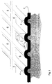
- FIG. 1 illustrates more precisely the manufacture of a reservoir in accordance with the invention. It represents, in section and in perspective, a metal mold (1), provided with ribs (2) with a profile devoid of sharp edges, used for molding a tank whose wall (3) is made of thermoplastic material.
- the ribs (2) of the mold cause similar ribs (4) to form on the inner surface of the tank.
- the mold has two networks perpendicular to ribs parallel to each other, which allows to form also, on the inner surface of the reservoir, perpendicular networks of ribs (4, 5) defining closed rectangular areas (6) lowered by relationship to the top of the ribs (4).
- Figure 2 schematically shows the bottom wall of a tank to fuel according to the invention.
- FIG. 2 schematically shows the bottom wall of a tank to fuel according to the invention.
Landscapes
- Engineering & Computer Science (AREA)
- Sustainable Development (AREA)
- Sustainable Energy (AREA)
- Chemical & Material Sciences (AREA)
- Combustion & Propulsion (AREA)
- Transportation (AREA)
- Mechanical Engineering (AREA)
- Life Sciences & Earth Sciences (AREA)
- Details Of Rigid Or Semi-Rigid Containers (AREA)
- Cooling, Air Intake And Gas Exhaust, And Fuel Tank Arrangements In Propulsion Units (AREA)
- Containers Having Bodies Formed In One Piece (AREA)
- Closures For Containers (AREA)
- Coating Apparatus (AREA)
- Pens And Brushes (AREA)
- Sampling And Sample Adjustment (AREA)
- Devices For Use In Laboratory Experiments (AREA)
Description
La présente invention concerne un type particulier de réservoir en matière plastique destiné à contenir un liquide tel que par exemple un carburant.The present invention relates to a particular type of material tank plastic intended to contain a liquid such as for example a fuel.
Une proportion croissante des réservoirs à carburant actuellement installés dans des véhicules sont essentiellement constitués de matière plastique. Toutefois, un problème bien connu de ce type de réservoirs concerne leur imperméabilité. En effet, les matières plastiques couramment utilisées pour leur fabrication, telles que les polyoléfines, ne sont pas totalement imperméables aux carburants généralement utilisés, et en particulier aux carburants contenant des alcools. L'imperméabilité constitue toutefois une caractéristique importante des réservoirs à carburant, en particulier en raison des normes officielles de plus en plus strictes concernant les émissions de vapeurs de carburant imposées aux véhicules automobiles.A growing proportion of the fuel tanks currently installed in vehicles are basically made of plastic. However, a well known problem with this type of tank concerns their impermeability. Indeed, the plastics commonly used for their manufacturing, such as polyolefins, are not completely impermeable to fuels generally used, and in particular to fuels containing alcohols. Impermeability is, however, an important characteristic of fuel tanks, especially due to increasingly official standards more stringent regarding fuel vapor emissions imposed on motor vehicles.
Diverses solutions ont déjà été proposées pour améliorer l'imperméabilité de réservoirs à base de matière plastique. Il est notamment courant de soumettre l'intérieur de réservoirs à carburant en matière plastique à un traitement superficiel approprié, par exemple à une fluoration ou à une sulfonation, comme décrit notamment dans les documents US 5213734 ou EP 695779 (SOLVAY (société anonyme)) l'ultérieur formant l'état de la téchnique le plus proche selon le préambule de la revendication 1. Un tel traitement superficiel conduit à la formation d'une mince couche barrière sur la surface intérieure du réservoir. Cette solution est très efficace à court et à moyen terme, mais on a constaté que dans certaines conditions d'utilisation, les mouvements du carburant à l'intérieur du réservoir provoquent une érosion de la couche barrière, et par conséquent une détérioration de l'imperméabilité du réservoir à long terme. Ce problème d'érosion, qui est particulièrement aigu dans les réservoirs montés sur des véhicules (en mouvement), peut être encore aggravé par la présence de particules solides (poussières, etc.) dans le carburant.Various solutions have already been proposed to improve the waterproofing of plastic-based tanks. It is particularly common to submit the interior of plastic fuel tanks to a surface treatment suitable, for example for fluorination or sulfonation, as described in particular in documents US 5,213,734 or EP 695,779 (SOLVAY (company anonymous)) the subsequent forming the closest state of the technique according to the preamble of claim 1. Such a surface treatment leads to the formation of a thin barrier layer on the inner surface of the tank. This solution is very effective in the short and medium term, but it has been found that in some conditions of use, fuel movements inside the tank cause erosion of the barrier layer, and therefore deterioration long-term impermeability of the tank. This erosion problem, which is particularly acute in tanks mounted on vehicles (in movement), may be further aggravated by the presence of solid particles (dust, etc.) in the fuel.
La présente invention vise à remédier à ce problème, et à fournir un réservoir en matière plastique ayant subi un traitement superficiel interne, qui, tout en pouvant être constitué de matières plastiques usuelles, présente une imperméabilité élevée et durable à long terme.The present invention aims to remedy this problem, and to provide a reservoir of plastic having undergone an internal surface treatment, which, while can be made of common plastics, has a high waterproofing and long-term durability.
Plus précisément, la présente invention concerne un réservoir à liquide essentiellement constitué de matière plastique, dont la surface intérieure a été traitée superficiellement en vue d'accroítre son imperméabilité audit liquide, caractérisé en ce qu'au moins une partie de la surface intérieure du réservoir est munie de protubérances aptes à entraver le déplacement du liquide.More specifically, the present invention relates to a liquid reservoir essentially made of plastic, the inner surface of which has been surface treated in order to increase its impermeability to said liquid, characterized in that at least part of the interior surface of the tank is provided with protrusions capable of hindering the movement of the liquid.
Un tel réservoir présente une imperméabilité élevée et durable, en particulier vis-à-vis de carburants. Ce résultat est d'autant plus surprenant que la présence des protubérances provoque inévitablement un accroissement de la superficie de la surface intérieure du réservoir, ainsi que des amincissements locaux de sa paroi, et que l'on s'attendrait dès lors à une détérioration de son imperméabilité.Such a tank has a high and lasting impermeability, in particular vis-à-vis fuels. This result is all the more surprising since the presence protuberances inevitably cause an increase in the area of the interior surface of the tank, as well as local thinning of its wall, and that we would therefore expect a deterioration in its impermeability.
Par réservoir à liquide, on entend désigner tout corps creux destiné à contenir un liquide. Le réservoir décrit ci-dessus est très avantageux lorsqu'on l'utilise comme réservoir à carburant. Cette application n'est toutefois pas limitative, le réservoir selon l'invention pouvant également, à titre d'exemple, servir de récipient pour hydrocarbures quelconques, pour solvants, etc. En particulier, le réservoir selon l'invention est avantageusement utilisé dans des véhicules automobiles.By liquid tank is meant any hollow body intended to contain liquid. The tank described above is very advantageous when used as a fuel tank. This application is not, however, limiting, the tank according to the invention which can also, for example, serve as a container for any hydrocarbons, for solvents, etc. In particular, the tank according to the invention is advantageously used in motor vehicles.
La matière plastique comprend un ou plusieurs polymères, ainsi qu'éventuellement un ou plusieurs additifs usuels tels que stabilisants, antioxydants, pigments, lubrifiants, ignifugeants, agents antistatiques, matières de charge et/ou de renforcement, etc. Le ou les polymères utilisés sont généralement des polymères thermoplastiques, et plus particulièrement des polyoléfines. Comme polymère, on préfère utiliser du polyéthylène (PE), en particulier du PE de haute densité (HDPE). Outre une couche intérieure essentiellement constituée d'au moins une matière plastique, le réservoir peut éventuellement comporter une ou plusieurs autres couches, à base d'une ou plusieurs matières plastiques identiques ou différentes. Selon une variante particulièrement simple, la paroi du réservoir est constituée d'une seule matière plastique, c'est-à-dire qu'il s'agit d'un réservoir monocouche. Ceci n'exclut pas la présence d'accessoires usuels tels que connexions de tubulures de remplissage et/ou de raccordement au moteur, inserts, etc., constitués de matériaux éventuellement différents.The plastic material includes one or more polymers, as well that possibly one or more usual additives such as stabilizers, antioxidants, pigments, lubricants, flame retardants, antistatic agents, load and / or reinforcement, etc. The polymer (s) used are generally thermoplastic polymers, and more particularly polyolefins. As polymer, it is preferred to use polyethylene (PE), in particular PE high density (HDPE). In addition to an essentially constituted inner layer at least one plastic, the tank may optionally include a or several other layers, based on one or more plastics identical or different. According to a particularly simple variant, the wall of the tank consists of a single plastic material, i.e. it is a single-layer tank. This does not exclude the presence of usual accessories such as connections of filling pipes and / or connection to the engine, inserts, etc., made of possibly different materials.
Lorsque la paroi du réservoir est entièrement constituée de matière thermoplastique, une technique couramment utilisée pour sa fabrication est l'extrusion-soufflage. Cette technique convient aussi bien aux réservoirs monocouches que multicouches. Un tel réservoir peut également être fabriqué par toute autre technique usuelle, par exemple par injection et soudage, par rotomoulage, etc.When the tank wall is made entirely of material thermoplastic, a technique commonly used for its manufacture is extrusion blow molding. This technique is equally suitable for tanks monolayers than multilayers. Such a tank can also be manufactured by any other usual technique, for example by injection and welding, by rotational molding, etc.
Les traitements superficiels utilisables en vue d'accroítre l'imperméabilité du réservoir, en particulier vis-à-vis de carburants, sont bien connus en tant que tels ; il s'agit par exemple de traitements de fluoration et/ou de sulfonation, ou encore de traitements corona, plasma, etc. De tels traitements superficiels peuvent être réalisés au moment même de la fabrication du réservoir ("procédés on-line") ou bien ultérieurement ("procédés off-line"), en une ou plusieurs étapes. Ce ou ces traitements peuvent concerner toute la surface intérieure du réservoir, ou seulement une ou certaines zones de cette surface. Ils conduisent à la formation d'une mince couche barrière sur la surface intérieure du réservoir. Par exemple, dans le cas d'un traitement de fluoration appliqué à un réservoir en polyéthylène, on peut obtenir la formation d'une couche de polyéthylène fluoré dont l'épaisseur est typiquement de quelques microns ou dixièmes de microns. L'invention donne de très bons résultats dans le cas où la surface intérieure du réservoir a été traitée par fluoration et/ou par sulfonation.Surface treatments that can be used to increase the impermeability of the tank, in particular with respect to fuels, are well known as such; these are, for example, fluorination and / or sulfonation treatments, or else corona, plasma, etc. Such superficial treatments can be carried out at the same time as the tank is manufactured ("on-line processes") or well later ("off-line processes"), in one or more stages. This or these treatments may relate to the entire interior surface of the tank, or only one or certain areas of this surface. They lead to training a thin barrier layer on the inside surface of the tank. For example, in the case of a fluorination treatment applied to a polyethylene tank, we can obtain the formation of a fluorinated polyethylene layer whose thickness is typically a few microns or tenths of a micron. The invention provides very good results in case the interior surface of the tank has been treated by fluorination and / or by sulfonation.
Les protubérances peuvent être de tout type, par exemple des plots ou des nervures, pourvu qu'elles soient aptes à entraver le déplacement du liquide à proximité immédiate de la partie de la surface intérieure du réservoir qui en est munie. Elles peuvent avantageusement se présenter sous la forme de nervures, qui peuvent notamment être rectilignes, polygonales et/ou courbes. Avantageusement, les nervures délimitent des zones fermées, par exemple des zones hexagonales ou rectangulaires, dont le centre ("le fond") est ainsi plus bas que le sommet des nervures. Il est par ailleurs avantageux que les protubérances soient espacées de manière substantiellement régulière. De très bons résultats ont été obtenus lorsque les nervures sont disposées selon des réseaux substantiellement perpendiculaires de nervures substantiellement rectilignes, parallèles et équidistantes, définissant ainsi des zones approximativement rectangulaires. Un avantage accessoire de la présence de ces protubérances est qu'elles peuvent contribuer à améliorer la résistance mécanique du réservoir (rigidification, etc.). Naturellement, la géométrie exacte des protubérances (par exemple leurs rayons de courbure dans un plan perpendiculaire à la paroi du réservoir) doit être choisie en respectant les contraintes imposées par le procédé de fabrication utilisé.The protrusions can be of any type, for example studs or ribs, provided that they are capable of hindering the movement of the liquid to immediate proximity to the part of the interior surface of the tank that is provided. They can advantageously be in the form of ribs, which can in particular be rectilinear, polygonal and / or curved. Advantageously, the ribs delimit closed areas, for example hexagonal or rectangular areas, the center ("bottom") of which is thus lower than the top of the ribs. It is also advantageous that the protrusions are spaced substantially evenly. Very good results have obtained when the ribs are arranged in networks substantially perpendicular to substantially rectilinear ribs, parallel and equidistant, thus defining zones approximately rectangular. An additional advantage of the presence of these protrusions is that they can help improve the mechanical strength of the tank (stiffening, etc.). Naturally, the exact geometry of the protrusions (by example their radii of curvature in a plane perpendicular to the wall of the tank) must be chosen while respecting the constraints imposed by the process of manufacturing used.
La hauteur des protubérances est généralement de l'ordre de quelques millimètres. Une hauteur d'au plus 20 mm, et de préférence d'au plus 15 mm, donne de bons résultats. Par ailleurs, la hauteur des protubérances est avantageusement d'au moins 3 mm, et de préférence d'au moins 5 mm.The height of the protrusions is generally of the order of a few millimeters. A height of at most 20 mm, and preferably at most 15 mm, gives good results. Furthermore, the height of the protrusions is advantageously at least 3 mm, and preferably at least 5 mm.
La largeur moyenne des protubérances (mesurée à mi-hauteur) est généralement du même ordre de grandeur que leur hauteur. Il est toutefois inutile de donner aux protubérances une largeur moyenne excessive, ce qui aurait pour conséquence d'accroítre la proportion de la superficie des protubérances par rapport à la superficie totale de la surface intérieure du réservoir, avec le risque d'une détérioration de son imperméabilité globale. La largeur moyenne des protubérances est habituellement fixée légèrement au-delà de la largeur minimale imposée par les contraintes liées au procédé de fabrication utilisé ; ainsi, dans la plupart des cas, cette largeur moyenne sera au moins deux fois égale à l'épaisseur de la paroi du réservoir. La largeur moyenne des protubérances est avantageusement supérieure à 3 fois l'épaisseur de la paroi du réservoir, et de préférence supérieure à 4 fois cette épaisseur. Par ailleurs, des largeurs moyennes inférieures à 6 fois cette épaisseur, et de préférence inférieures à 5 fois cette épaisseur, ont donné de bons résultats.The average width of the protrusions (measured at mid-height) is generally of the same order of magnitude as their height. It is however unnecessary to give the protrusions an excessive average width, which would have consequence of increasing the proportion of the area of the protrusions by compared to the total area of the interior surface of the tank, with the risk deterioration of its overall waterproofing. The average width of protrusions is usually fixed slightly beyond the minimum width imposed by the constraints linked to the manufacturing process used; so in the in most cases this average width will be at least twice the thickness of the tank wall. The average width of the protrusions is advantageously greater than 3 times the thickness of the wall of the tank, and preferably more than 4 times this thickness. In addition, average widths less than 6 times this thickness, and preferably less than 5 times this thickness, have given good results.
L'écartement entre deux nervures voisines est généralement de l'ordre de quelques dizaines de millimètres. Il s'est révélé avantageux que l'écartement des protubérances soit d'au moins 3 fois leur hauteur, et de préférence d'au moins 4 fois leur hauteur. Par ailleurs, cet écartement est avantageusement d'au plus 9 fois leur hauteur, et de préférence d'au plus 6 fois leur hauteur. Un écartement d'au moins 20 mm, et en particulier d'au moins 35 mm, donne de bons résultats. Par ailleurs, l'écartement est avantageusement d'au plus 100 mm, et de préférence d'au plus 70 mm.The spacing between two neighboring ribs is generally of the order of a few tens of millimeters. It has proven advantageous that the spacing of the protrusions is at least 3 times their height, and preferably at least 4 times their height. Furthermore, this spacing is advantageously at most 9 times their height, and preferably at most 6 times their height. A spacing at least 20 mm, and in particular at least 35 mm, gives good results. Furthermore, the spacing is advantageously at most 100 mm, and preferably not more than 70 mm.
La totalité de la surface intérieure du réservoir peut être munie de protubérances. Toutefois, normalement, l'érosion s'exerce principalement sur la paroi inférieure du réservoir, qu'il s'agisse de l'érosion due aux mouvements du liquide ou à d'éventuelles particules solides. Dès lors, il est avantageux qu'au moins la paroi inférieure de la surface intérieure du réservoir soit munie de protubérances. Selon une variante particulièrement simple de la présente invention, seule cette paroi inférieure est munie de protubérances. (Par paroi inférieure, on entend désigner la paroi qui forme le fond du réservoir lorsque celui-ci se trouve dans sa position d'utilisation normale.)The entire interior surface of the tank can be fitted with protuberances. Normally, however, erosion takes place mainly on the bottom wall of the tank, whether erosion due to movements of the liquid or any solid particles. Therefore, it is advantageous that minus the bottom wall of the interior surface of the tank is provided with protuberances. According to a particularly simple variant of this invention, only this bottom wall is provided with protuberances. (By wall means to designate the wall which forms the bottom of the tank when it is in its normal use position.)
Les protubérances peuvent être réalisées par toute technique appropriée. Ainsi, par exemple, des nervures préfabriquées se présentant sous la forme d'une ou plusieurs grilles d'un matériau adéquat, peuvent être fixées sur la surface intérieure du réservoir pendant ou après sa fabrication.The protrusions can be produced by any suitable technique. Thus, for example, prefabricated ribs in the form of a or several grids of a suitable material, can be fixed on the surface inside the tank during or after its manufacture.
On préfère toutefois que les protubérances fassent partie intégrante de la paroi du réservoir. A cette fin, des éléments en relief de formes et de dimensions appropriées peuvent être présents à la surface du moule utilisé pour la fabrication du réservoir, en vue de créer des protubérances dans la paroi du réservoir lors de sa fabrication par moulage. Ces éléments en relief peuvent faire partie intégrante du moule, ou avoir été fixés ultérieurement à un moule classique préexistant. Cette variante est avantageuse dans la mesure où elle permet la réutilisation de moules existants moyennant des modifications mineures. On peut encore utiliser un moule muni d'éléments en relief mobiles (rétractables), dont on provoque le déplacement à un moment donné du processus de fabrication.However, it is preferred that the protrusions are an integral part of the tank wall. To this end, relief elements of shapes and dimensions suitable may be present on the surface of the mold used for manufacturing of the tank, in order to create protuberances in the wall of the tank during its manufacture by molding. These raised elements can be an integral part of the mold, or having been subsequently fixed to a preexisting conventional mold. This variant is advantageous insofar as it allows the reuse of existing molds with minor modifications. We can still use a mold provided with movable elements in relief (retractable), which one causes the displacement at a given point in the manufacturing process.
Les figures annexées illustrent de façon non limitative l'invention.The appended figures illustrate the invention without limitation.
La figure 1 illustre plus précisément la fabrication d'un réservoir conforme à l'invention. Elle représente, en coupe et en perspective, un moule métallique (1), muni de nervures (2) au profil dépourvu d'arêtes vives, servant au moulage d'un réservoir dont la paroi (3) est constituée de matière thermoplastique. Les nervures (2) du moule provoquent la formation de nervures (4) similaires sur la surface intérieure du réservoir. Le moule est muni de deux réseaux perpendiculaires de nervures parallèles entre elles, ce qui permet de former également, sur la surface intérieure du réservoir, des réseaux perpendiculaires de nervures (4, 5) définissant des zones fermées rectangulaires (6) surbaissées par rapport au sommet des nervures (4).FIG. 1 illustrates more precisely the manufacture of a reservoir in accordance with the invention. It represents, in section and in perspective, a metal mold (1), provided with ribs (2) with a profile devoid of sharp edges, used for molding a tank whose wall (3) is made of thermoplastic material. The ribs (2) of the mold cause similar ribs (4) to form on the inner surface of the tank. The mold has two networks perpendicular to ribs parallel to each other, which allows to form also, on the inner surface of the reservoir, perpendicular networks of ribs (4, 5) defining closed rectangular areas (6) lowered by relationship to the top of the ribs (4).
On notera que les lignes pointillées visibles sur la figure 1 ne correspondent pas à des arêtes vives, mais à des raccordements progressifs (arrondis). On notera également que la figure 1 n'est que schématique, et que les dimensions et proportions des différents éléments qui y sont représentés ont été exclusivement choisies en vue de clarifier la figure.Note that the dotted lines visible in Figure 1 do not match not with sharp edges, but with progressive (rounded) connections. We also note that figure 1 is only schematic, and that the dimensions and proportions of the various elements represented there have been exclusively chosen to clarify the figure.
La figure 2 représente schématiquement la paroi inférieure d'un réservoir à carburant conforme à l'invention. On y distingue plusieurs réseaux de nervures parallèles, perpendiculaires deux à deux.Figure 2 schematically shows the bottom wall of a tank to fuel according to the invention. There are several networks of ribs parallel, perpendicular two by two.
Claims (10)
- Tank for a liquid, made essentially of plastic, the interior surface (1) of which has been surface treated so as to increase its impermeability to the said liquid, characterized in that at least part of the interior surface (1) of the tank has protrusions (4, 5) capable of impeding the movement of the liquid.
- Fuel tank according to Claim 1.
- Tank according to one of the preceding claims, in which the wall of the tank consists of a single plastic.
- Tank according to one of the preceding claims, in which the interior surface of the tank has been treated by fluoration and/or by sulphonation.
- Tank according to one of the preceding claims, in which the protrusions are in the form of ribs (4, 5).
- Tank according to the preceding claim, in which the ribs delimit closed zones.
- Tank according to the preceding claim, in which the ribs are arranged in roughly perpendicular networks of roughly straight (4, 5), parallel and equidistant ribs.
- Tank according to one of the preceding claims, in which the protrusions are at most 20 mm tall.
- Tank according to one of the preceding claims, in which the protrusions have a spacing of 20 to 100 mm.
- Tank according to one of the preceding claims, in which at least the lower wall of the interior surface of the tank has protrusions.
Applications Claiming Priority (2)
| Application Number | Priority Date | Filing Date | Title |
|---|---|---|---|
| BE9700800A BE1011483A3 (en) | 1997-10-03 | 1997-10-03 | Tank. |
| BE9700800 | 1997-10-03 |
Publications (2)
| Publication Number | Publication Date |
|---|---|
| EP0906843A1 EP0906843A1 (en) | 1999-04-07 |
| EP0906843B1 true EP0906843B1 (en) | 2002-09-04 |
Family
ID=3890761
Family Applications (1)
| Application Number | Title | Priority Date | Filing Date |
|---|---|---|---|
| EP19980203172 Expired - Lifetime EP0906843B1 (en) | 1997-10-03 | 1998-09-21 | Tank |
Country Status (5)
| Country | Link |
|---|---|
| EP (1) | EP0906843B1 (en) |
| AR (1) | AR017289A1 (en) |
| BE (1) | BE1011483A3 (en) |
| BR (1) | BR9803868A (en) |
| DE (1) | DE69807614T2 (en) |
Families Citing this family (1)
| Publication number | Priority date | Publication date | Assignee | Title |
|---|---|---|---|---|
| DE102019125403A1 (en) * | 2019-09-20 | 2021-03-25 | Kautex Textron Gmbh & Co. Kg | PLASTIC CONTAINERS FOR MOTOR VEHICLES WITH AT LEAST ONE REINFORCEMENT STRUCTURE |
Family Cites Families (3)
| Publication number | Priority date | Publication date | Assignee | Title |
|---|---|---|---|---|
| DE3641356C1 (en) * | 1986-12-03 | 1988-07-07 | Daimler Benz Ag | Fuel tanks for vehicles |
| BE1004647A3 (en) | 1991-02-20 | 1993-01-05 | Solvay | PROCESS FOR PRODUCING HOLLOW BODIES IN THERMOPLASTIC MATERIAL BY BLOW MOLDING HAVING IMPROVED GAS WATERPROOFING. |
| BE1008568A3 (en) | 1994-07-20 | 1996-06-04 | Solvay | PROCESS FOR THE SURFACE TREATMENT OF ITEM AND SILENCE by sulfonation. |
-
1997
- 1997-10-03 BE BE9700800A patent/BE1011483A3/en not_active IP Right Cessation
-
1998
- 1998-09-21 DE DE1998607614 patent/DE69807614T2/en not_active Expired - Fee Related
- 1998-09-21 EP EP19980203172 patent/EP0906843B1/en not_active Expired - Lifetime
- 1998-10-02 AR ARP980104938 patent/AR017289A1/en active IP Right Grant
- 1998-10-02 BR BR9803868A patent/BR9803868A/en not_active Application Discontinuation
Also Published As
| Publication number | Publication date |
|---|---|
| AR017289A1 (en) | 2001-09-05 |
| BE1011483A3 (en) | 1999-10-05 |
| DE69807614D1 (en) | 2002-10-10 |
| DE69807614T2 (en) | 2003-05-15 |
| BR9803868A (en) | 1999-12-14 |
| EP0906843A1 (en) | 1999-04-07 |
Similar Documents
| Publication | Publication Date | Title |
|---|---|---|
| FR2873321A1 (en) | METHOD FOR FIXING AN ACCESSORY IN A FUEL TANK OF PLASTIC MATERIAL | |
| BE1009534A3 (en) | Method for fixing an element within a hollow thermoplastic. | |
| EP0621207B1 (en) | Profile for protecting objects in particular against shock | |
| EP0906843B1 (en) | Tank | |
| EP1190837A1 (en) | Multilayer hollow body, manufacturing method therefor and blow mould with compression borders | |
| FR3094944A1 (en) | Reinforcement insert in composite material fitted with anchoring elements | |
| EP1439974B1 (en) | System and method for sealing a tank opening | |
| WO2005014320A1 (en) | Glazing comprising a reinforcement element | |
| FR2937581A1 (en) | PROCESS FOR THE MANUFACTURE OF A FUEL TANK OF PLASTIC MATERIAL WITH A GAUGE | |
| FR2807700A1 (en) | SYNTHETIC FUEL TANK AND MANUFACTURING METHOD THEREOF | |
| LU102744B1 (en) | Mold set for manufacturing a motor vehicle tank | |
| EP3230108B1 (en) | System for a motor vehicle | |
| BE1006436A3 (en) | Thermoplastic multi tank for storage of oil. | |
| BE1030933B1 (en) | MOLD, MOLDING MACHINE AND EXTRUSION BLOW MOLDING METHOD | |
| WO2012080082A1 (en) | Arrangement of two parts made of thermoplastic materials to be assembled by laser welding | |
| FR3134165A3 (en) | Lighting device for a motor vehicle | |
| EP3668736B1 (en) | Support box for battery | |
| FR2919534A1 (en) | FUEL TANK OF PLASTIC MATERIAL | |
| FR3120353A1 (en) | Improved Bottom Bottle | |
| FR3053936B1 (en) | MULTI-CARBON FUEL TANK AND METHOD OF MANUFACTURE | |
| EP1072393B1 (en) | Hollow body and method for manufacturing this hollow body | |
| WO2006092472A1 (en) | Method for molding a profiled weatherstrip on a glazing | |
| WO2007146216A1 (en) | Sulfonated fuel tank | |
| CA2928809C (en) | Preform having a star-shaped bottom and corresponding container | |
| FR2710002A1 (en) | Device for extruding a pipe having various wall thicknesses |
Legal Events
| Date | Code | Title | Description |
|---|---|---|---|
| PUAI | Public reference made under article 153(3) epc to a published international application that has entered the european phase |
Free format text: ORIGINAL CODE: 0009012 |
|
| AK | Designated contracting states |
Kind code of ref document: A1 Designated state(s): BE DE ES FR GB IT PT |
|
| AX | Request for extension of the european patent |
Free format text: AL;LT;LV;MK;RO;SI |
|
| 17P | Request for examination filed |
Effective date: 19991007 |
|
| AKX | Designation fees paid |
Free format text: BE DE ES FR GB IT PT |
|
| GRAG | Despatch of communication of intention to grant |
Free format text: ORIGINAL CODE: EPIDOS AGRA |
|
| 17Q | First examination report despatched |
Effective date: 20011127 |
|
| GRAG | Despatch of communication of intention to grant |
Free format text: ORIGINAL CODE: EPIDOS AGRA |
|
| GRAH | Despatch of communication of intention to grant a patent |
Free format text: ORIGINAL CODE: EPIDOS IGRA |
|
| GRAH | Despatch of communication of intention to grant a patent |
Free format text: ORIGINAL CODE: EPIDOS IGRA |
|
| RAP1 | Party data changed (applicant data changed or rights of an application transferred) |
Owner name: INERGY AUTOMOTIVE SYSTEMS RESEARCH (SA) |
|
| GRAA | (expected) grant |
Free format text: ORIGINAL CODE: 0009210 |
|
| AK | Designated contracting states |
Kind code of ref document: B1 Designated state(s): BE DE ES FR GB IT PT |
|
| PG25 | Lapsed in a contracting state [announced via postgrant information from national office to epo] |
Ref country code: IT Free format text: LAPSE BECAUSE OF FAILURE TO SUBMIT A TRANSLATION OF THE DESCRIPTION OR TO PAY THE FEE WITHIN THE PRE;WARNING: LAPSES OF ITALIAN PATENTS WITH EFFECTIVE DATE BEFORE 2007 MAY HAVE OCCURRED AT ANY TIME BEFORE 2007. THE CORRECT EFFECTIVE DATE MAY BE DIFFERENT FROM THE ONE RECORDED.SCRIBED TIME-LIMIT Effective date: 20020904 Ref country code: GB Free format text: LAPSE BECAUSE OF FAILURE TO SUBMIT A TRANSLATION OF THE DESCRIPTION OR TO PAY THE FEE WITHIN THE PRESCRIBED TIME-LIMIT Effective date: 20020904 |
|
| REG | Reference to a national code |
Ref country code: GB Ref legal event code: FG4D Free format text: NOT ENGLISH |
|
| REF | Corresponds to: |
Ref document number: 69807614 Country of ref document: DE Date of ref document: 20021010 |
|
| PG25 | Lapsed in a contracting state [announced via postgrant information from national office to epo] |
Ref country code: PT Free format text: LAPSE BECAUSE OF FAILURE TO SUBMIT A TRANSLATION OF THE DESCRIPTION OR TO PAY THE FEE WITHIN THE PRESCRIBED TIME-LIMIT Effective date: 20021213 |
|
| GBV | Gb: ep patent (uk) treated as always having been void in accordance with gb section 77(7)/1977 [no translation filed] |
Effective date: 20020904 |
|
| PG25 | Lapsed in a contracting state [announced via postgrant information from national office to epo] |
Ref country code: ES Free format text: LAPSE BECAUSE OF FAILURE TO SUBMIT A TRANSLATION OF THE DESCRIPTION OR TO PAY THE FEE WITHIN THE PRESCRIBED TIME-LIMIT Effective date: 20030328 |
|
| PLBE | No opposition filed within time limit |
Free format text: ORIGINAL CODE: 0009261 |
|
| STAA | Information on the status of an ep patent application or granted ep patent |
Free format text: STATUS: NO OPPOSITION FILED WITHIN TIME LIMIT |
|
| 26N | No opposition filed |
Effective date: 20030605 |
|
| PGFP | Annual fee paid to national office [announced via postgrant information from national office to epo] |
Ref country code: FR Payment date: 20030909 Year of fee payment: 6 |
|
| PGFP | Annual fee paid to national office [announced via postgrant information from national office to epo] |
Ref country code: DE Payment date: 20031002 Year of fee payment: 6 |
|
| PGFP | Annual fee paid to national office [announced via postgrant information from national office to epo] |
Ref country code: BE Payment date: 20041122 Year of fee payment: 7 |
|
| PG25 | Lapsed in a contracting state [announced via postgrant information from national office to epo] |
Ref country code: DE Free format text: LAPSE BECAUSE OF NON-PAYMENT OF DUE FEES Effective date: 20050401 |
|
| PG25 | Lapsed in a contracting state [announced via postgrant information from national office to epo] |
Ref country code: FR Free format text: LAPSE BECAUSE OF NON-PAYMENT OF DUE FEES Effective date: 20050531 |
|
| REG | Reference to a national code |
Ref country code: FR Ref legal event code: ST |
|
| PG25 | Lapsed in a contracting state [announced via postgrant information from national office to epo] |
Ref country code: BE Free format text: LAPSE BECAUSE OF NON-PAYMENT OF DUE FEES Effective date: 20050930 |
|
| BERE | Be: lapsed |
Owner name: S.A. *INERGY AUTOMOTIVE SYSTEMS RESEARCH Effective date: 20050930 |