EP0913696A2 - Modular apparatus for metering of electric energy - Google Patents
Modular apparatus for metering of electric energy Download PDFInfo
- Publication number
- EP0913696A2 EP0913696A2 EP98660101A EP98660101A EP0913696A2 EP 0913696 A2 EP0913696 A2 EP 0913696A2 EP 98660101 A EP98660101 A EP 98660101A EP 98660101 A EP98660101 A EP 98660101A EP 0913696 A2 EP0913696 A2 EP 0913696A2
- Authority
- EP
- European Patent Office
- Prior art keywords
- compartment
- auxiliary function
- cards
- cover
- box
- Prior art date
- Legal status (The legal status is an assumption and is not a legal conclusion. Google has not performed a legal analysis and makes no representation as to the accuracy of the status listed.)
- Granted
Links
Images


Classifications
-
- G—PHYSICS
- G01—MEASURING; TESTING
- G01R—MEASURING ELECTRIC VARIABLES; MEASURING MAGNETIC VARIABLES
- G01R22/00—Arrangements for measuring time integral of electric power or current, e.g. electricity meters
- G01R22/06—Arrangements for measuring time integral of electric power or current, e.g. electricity meters by electronic methods
- G01R22/061—Details of electronic electricity meters
- G01R22/065—Details of electronic electricity meters related to mechanical aspects
-
- G—PHYSICS
- G01—MEASURING; TESTING
- G01R—MEASURING ELECTRIC VARIABLES; MEASURING MAGNETIC VARIABLES
- G01R22/00—Arrangements for measuring time integral of electric power or current, e.g. electricity meters
Definitions
- the invention concerns an apparatus for metering of electric energy as defined in the preamble of claim 1.
- Auxiliary apparatuses installed in the interior of the meter are favoured, because they reduce the cost of installation and the overall space required by the meter construction.
- Such a solution involves the problem that, in connection with replacement or after-installation of auxiliary apparatuses, the meter box must be opened, and the calibration seal provided on one screw that keeps the meter box closed must be broken. This is why, after replacement or after-installation of the auxiliary apparatuses, the meter must be calibrated again in a meter repair workshop, which causes additional expenses.
- a box of a meter for electric energy consisting of a bottom plate and of a box-like cover part is described.
- the cover part there is an opening that can be closed by means of a separate cover.
- Onto the bottom plate first the cover part is installed, which is closed in relation to the bottom plate by means of seals. After this, onto the opening on the cover part, the cover is fitted, which is closed in relation to the cover part by means of seals.
- an auxiliary function card can be installed.
- access is provided to the compartment that receives the auxiliary function card through the front face (cover face) of the box.
- the auxiliary function card can be replaced without breaking the seals on the cover part.
- auxiliary cards which consist of integrated electronic circuit cards that include one or several functional properties, can be connected.
- This compartment for auxiliary cards has been designed so that its front side, through which the cards of auxiliary functions are inserted into the compartment and removed from the compartment, is opened into the side wall of the meter box placed at the side of the connector block.
- an opening has been arranged so that through this opening access is provided to the cards for auxiliary functions without opening the cover of the meter box.
- Said opening can be closed by means of a separate cover of its own which can be sealed, or said opening can also be placed under the cover of the connector block provided at the side wall of the box, in which case access to said compartment is provided so that the cover of the connector block is opened, which cover is also a cover that can be closed by means of a seal.
- auxiliary card compartment of the metering apparatus for example, a pulse input/output card, serial interface card, LON data transfer card, network command receiver card, receiver/transmitter card for the "MELKO" system, telephone modem card, radio modem card can be installed. It is also possible to think that the auxiliary function card contains additional memory for the meter only.
- the auxiliary card compartment has also been designed so that an electric connection is formed between the auxiliary function card or cards and the other electronic circuits of the meter when the auxiliary function card or cards is/are installed on the connector means of said compartment. Further, the auxiliary function cards have been designed so that they can also be connected to apparatuses outside the meter when the opening placed in the side wall of the box and passing to the auxiliary device compartment is open.
- the auxiliary card compartment has been designed so that it has a detachable partition wall, by whose means the auxiliary card compartment can be divided into two parts.
- the partition wall is not in its place, one auxiliary function card that extends across the whole width of the auxiliary card compartment can be installed into the auxiliary card compartment, and when the partition wall is in its place, two narrower auxiliary function cards placed side by side can be installed into the auxiliary card compartment.
- the auxiliary card compartment can be so high that the auxiliary function cards can be fitted one above the other in the auxiliary card compartment. In most cases, however, an auxiliary card compartment is likely to be sufficient in which there is space for no more than two auxiliary function cards.
- the auxiliary card compartment of the apparatus for metering of electric energy in accordance with the invention is also provided with a lock device that can be operated from inside the meter box.
- a lock device that can be operated from inside the meter box.
- the construction in accordance with the invention of an apparatus for metering of electric energy can be used both in connection with a three-phase meter and in connection with a single-phase meter.
- As the circuit of metering of electric energy in the meter in principle, it is possible to employ any static metering circuit whatsoever, to which circuit, when necessary, different metering devices are connected.
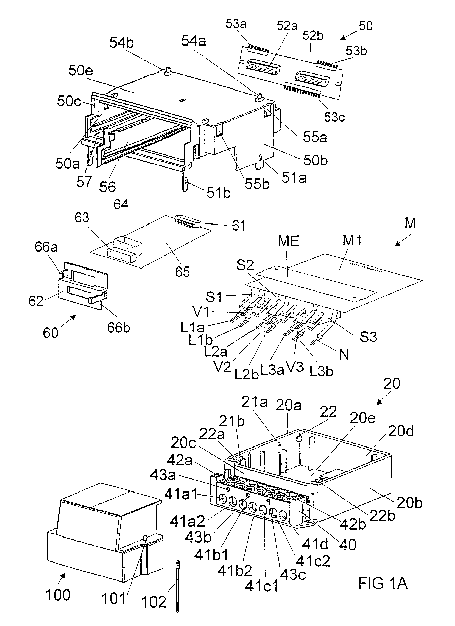
- FIGS. 1A and 1B are an exploded view illustrating the modules of the apparatus for metering of electric energy in accordance with the invention.
- Figure illustrates a lock device for the auxiliary function cards.
- the apparatus for metering of electric energy in accordance with the present invention shown in Figs. 1A and 1B consists of a box-like case, which comprises a bottom part 20 and a cover part 30.
- the bottom part 20 of the box consists of a first side wall 20a, a second side wall 20b, a front wall 20c, a rear wall 20d, and of a bottom plate 20e.
- a connector block 40 in the front wall 20c of the bottom part 20 of the box, there is a connector block 40, to whose terminals 41a1, 41b1, 41c1 the phase conductors of the electricity feed cable coming from the distribution network of the electricity plant are connected.
- the phase conductors of the electricity feed cable of the consumption site supplied through the meter are again connected to the terminals 41a2, 41b2, 41c2 of the connector block 40.
- the terminal 41d in the connector block 40 is the neutral terminal. If a meter connected to a current transformer / voltage transformer is used, the terminals 43a, 43b, 43c are connected to the phases of the electricity network or to the voltage metering transformers.
- the metering module M consists of an integrated electronic circuit card M1, of connected current metering transformers S1, S2, S3, and of connector strips L1a, L1b, L2a, L2b, L3a, L3b, N, V1, V2, V3 fitted onto the terminals 41a1, 41a2, 41b1, 41b2, 41c1, 41c2, 41d, 43a, 43b, 43c in the connector block 40 on the front wall 20c of the bottom part 20 of the box.
- a metering module M for three-phase electric energy in which the connector strips Lla and Llb are connected with the first phase, the connector strips L2a and L2b with the second phase, the connector strips L3a and L3b with the third phase, and the connector strip N with neutral.
- the connector strips L1a, L1b, L2a, L2b, L3a, L3b are connected through said current transformers S1, S2, S3 to the circuit card Ml of the metering module M.
- the connector strip N is connected directly to the circuit card M1 of the metering module M.
- the connector strips V1, V2, V3 are connected to the phases of the electricity network, or to voltage metering transformers when a meter connected to a current transformer / voltage transformer is concerned.
- an interference protection plate ME Onto the circuit card Ml at the current transformers S1, S2, S3, an interference protection plate ME has been installed, by whose means transfer of any interference that may be produced by the current transformers S1, S2, S3 to the other electronic circuits of the meter, placed above the metering module M, is prevented.
- the circuit card Ml of the metering module M is placed substantially at the level of the top edges of the side walls 20a, 20b, front wall 20c, and rear wall 20d of the bottom part 20a of the box 20.
- the compartment that receives the auxiliary function cards consists of a frame part 50, which comprises a first 50a and a second side wall 50b, a deck plate 50e that interconnects said side walls, a detachable rear circuit card 50d, a front wall 50c provided with an opening, and a detachable partition wall 56.
- the rear circuit card 50d of the frame part 50 can be attached to the side walls 50a, 50b of the frame part 50, for example, by means of screws.
- the rear circuit card 50d of the frame part 50 includes the connector interfaces 52a, 52b for auxiliary function cards 60 as well as the connectors 53a, 53b, 53c.
- the connectors 53a, 53b are connected to the application module 70 to be fitted on the top of the frame part 50, and the connector 53c is connected to the metering module M placed at the bottom of the frame part 50.
- the frame part 50 is installed onto the metering module M so that the side walls 50a, 50b of the frame part 50 enclose the circuit card Ml of the metering module M.
- the side walls 50a, 50b of the frame part 50 are provided with first projections 51a, 51b, which are positioned into the openings 21a, 21b provided in the inner faces of the side walls 20a, 20b of the bottom part 20 of the box 10 and lock the frame part 50 in its position.
- the auxiliary function cards 60 consist of an integrated electronic circuit card 65, in whose rear part there is a connector 61, which is fitted into the connector 52a, 52b in the rear wall 50d of the frame part 50 and forms a contact between the connector pins of said connectors when the auxiliary function card 60 is pushed into the frame part 50 along the guide grooves 57.
- a fastening device 62 At the front edges of the auxiliary function cards 60, there is/are one or several connectors 63, 64, by whose means the auxiliary function card 60 can be connected to apparatuses outside the meter.
- the auxiliary function cards 60 are attached to the frame part 50 by means of a fastening device 62.
- the fastening device 62 includes two clamp devices 66a, 66b, by whose means the fastening device 62 and, thereby, the auxiliary function card 60 are attached to the frame part 50 so that they cannot glide out of the frame part 50.
- the fastening device 62 it is also possible to close the opening in the front wall 50c of the frame part 50 while there is/are no auxiliary function card or cards fitted in their place in the frame part 50.
- the application module 70 which also consists of an integrated electronic circuit card 71, is installed onto the fastening pins 54a, 54b provided on the deck plate 50d of the frame part 50 for auxiliary function cards 60. Further, the application module 70 may include a battery 72, by whose means the supply of electricity to the clock circuits of the circuit card 71 of the application module is secured during breaks of supply in the mains network.
- the application module 70 also includes connectors 73a, 73b that receive the connector pins of the connectors 53a, 53b on the rear wall 50c of the frame part 50. Further, the application module 70 includes a display 74, by whose means the consumption of electric energy metered by the meter is displayed.
- the application module 70 includes a user interface and all functions that are connected with the collecting, processing and storage of the metering data.
- a name plate 90 is fitted, and the topmost part will be the cover part 30 of the box, which is positioned against the bottom part 20 of the box and encloses the apparatuses installed on said bottom part 20.
- the cover part 30 consists of a first side wall 30a, of a second side wall 30b, of a front wall 30c, of a rear wall 30d, and of a deck plate 30e interconnecting said walls.
- the cover part 30 is further connected with a closing gate 31, which can be pushed into the grooves 32 provided on the cover part.
- the cover part 30 is attached to the bottom part 20 by means of notches 34 provided in projections 33 provided on the side walls 30a, 30b of the cover part near the rear wall 30d, which notches 34 are fitted into engagement with projections 22 provided on the inside faces of the side walls 20a, 20b of the bottom part 20.
- an opening 37 remains at the forward edge 30c of the cover part 30, through which opening access is provided to the front edge 50c of the frame part 50 which receives the auxiliary function cards 60.
- an auxiliary function card 60 can be pushed into the frame part 50.
- the cover 100 of the connector block 40 can be fitted in its place on the connector block 40.
- the cover 100 of the connector block extends upwards so that, besides the connector block 40, it also covers the opening 37 at the front edge 30c of the cover part 30 of the box and, thus, also the auxiliary function cards 60.
- At the sides of the cover 100 of the connector block 40 there are holes 101, from which the cover 100 can be attached by means of screws 102 to corresponding threaded holes 42a, 42b provided on the connector block 40. At least one of the screws 102 can again be provided with a seal so that the screw 102 cannot be opened without breaking the seal.
- Fig. 2 shows a lock device 110 attached to the rear circuit card 50d of the frame part 50, by means of which lock device the auxiliary function cards 60a, 60b can be locked on the frame part 50.
- the lock device 110 consists of a rotatable spindle part 112, whose end that is directed towards the rear circuit card 50d of the frame part 50 is provided with a slot 111 and whose end that is directed towards the interior of the frame part 50 is provided with wings 113a, 113b projecting in opposite directions.
- the spindle part 112 is placed in a vertical support 114 attached to the deck plate 50e of the frame part 50 and directed downwards.
- the auxiliary function cards 60a, 60b can be removed from their place by pulling them through the opening 37 out of the frame 50.
- the auxiliary function cards 60a, 60b glide on support of the guide grooves 57 provided on the side walls 50a, 50b and on the partition wall 56 in the frame part 50 out of the frame part 50, and the connectors 52a, 61a and 52b, 61b are separated from one another.
- the spindle part 112 has been arranged preferably so that it is locked in the position in which the wings 113a, 113b are in a substantially horizontal plane and in the position in which they are in a substantially vertical plane.
- This can be arranged, for example, so that onto the support column 114 a projection of quadrangular section is provided, which extends into a recess, likewise of quadrangular section, that has been formed into the spindle part 112.
- the spindle part 112 and said projection on the support column are locked with each other when the quadrangles coincide with each other, but, since the walls of the recess in the spindle part 112 yield slightly, the spindle part 112 can be forced, by rotating by means of a tool from the slot 111, to be shifted between the two locking positions mentioned above.
- the lock device 110 is shown in a situation in which there is a partition wall 56 in the frame part 50 and in which two smaller auxiliary function cards 60a, 60b have been inserted into the frame part 50.
- the lock device 110 also operates in a situation in which there is an auxiliary function card, e.g. 60a, in one of the compartments separated by the partition wall 56 only, whereas the other compartment is empty.
- the lock device 110 can, of course, also be used in a situation in which there is no partition wall 56 in the frame part 50 and in which one larger auxiliary function card 60 has been inserted into the frame part 50.
Landscapes
- Power Engineering (AREA)
- Physics & Mathematics (AREA)
- General Physics & Mathematics (AREA)
- Engineering & Computer Science (AREA)
- Measuring Volume Flow (AREA)
- Arrangements For Transmission Of Measured Signals (AREA)
- Measurement Of Resistance Or Impedance (AREA)
- Measurement Of Current Or Voltage (AREA)
- Crystals, And After-Treatments Of Crystals (AREA)
- Measurement Of Radiation (AREA)
- Electrotherapy Devices (AREA)
- Infusion, Injection, And Reservoir Apparatuses (AREA)
- Measuring Pulse, Heart Rate, Blood Pressure Or Blood Flow (AREA)
- Dry Shavers And Clippers (AREA)
Abstract
Description
Claims (11)
- A modular apparatus for metering of electric energy, which comprises a box-like case composed of a bottom part (20) and of a cover part (30) which can be attached to the bottom part and closed by means of a calibration seal, which case comprises a first side wall (20a, 30a), a second side wall (20b, 30b) opposite to the first side wall, a third side wall (20c, 30c), which interconnects the first edges of the first and the second side wall, a fourth side wall (20d, 30d) which is opposite to the third side wall and which interconnects the second edges of the first and the second side wall, as well as a bottom plate (20e), which interconnects the first ends of said side walls, and a deck plate (30e), which is opposite to the bottom plate and which interconnects the second ends of said side walls, in which connection an number of modules (M, 50, 70, 80, 90) that perform different functions have been fitted in the interior of the box (10), of which modules at least one module is a metering circuit (M) that meters electric energy, and which apparatus comprises a connector block (40) fitted to a side wall (20c) of the bottom part (20) and a cover (100) that covers the connector block, characterized in that the box also contains a compartment (50) that receives at least one auxiliary function card (60), which compartment (50) is opened in an opening (37) provided in the side wall (30c) of the cover part (30) at the side of the connector block (40), through which opening the auxiliary function card (60) or cards can be installed into the compartment (50) and removed from the compartment (50) so that the cover part (30) of the box does not have to be separated from the bottom part (20) of the box, in which case the calibration seal of the metering apparatus does not have to be broken either.
- A metering apparatus as claimed in claim 1, characterized in that the apparatus comprises a cover (100) of the connector block (40), which cover, when installed in its place, besides closing the access to the connectors on the connector block (40), also extends to close the access to the opening (37) passing into said compartment (50) that receives the auxiliary function card (60) or cards, in which case it is possible to replace the auxiliary function card (60) or cards by removing the cover (100) of the connector block (40).
- A metering apparatus as claimed in claim 1, characterized in that the apparatus comprises a separate cover, by whose means the opening (37) passing into the compartment (50) that receives the auxiliary function card (60) or cards is closed, in which case the auxiliary function card (60) or cards can be replaced so that said separate cover is removed.
- A metering apparatus as claimed in any of the claims 1 to 3, characterized in that the auxiliary function cards (60) are placed in said compartment (50) on a number of levels.
- A metering apparatus as claimed in any of the claims 1 to 3, characterized in that the auxiliary function cards (60) are placed in said compartment (50) on one level.
- A metering apparatus as claimed in claim 4, characterized in that said compartment (50) can be divided by means of a detachable partition wall (56) into two parts, in which case, after the partition wall (56) has been removed, a number of auxiliary function cards (60) placed on different levels and extending across the width of the whole compartment (50) can be fitted in the compartment (50), and, when the partition wall (56) is in its place, a number of auxiliary function cards (60) can be fitted in the compartment (50) so that they are placed on a number of levels, on each of which levels there are two auxiliary function cards (60) placed side by side.
- A metering apparatus as claimed in claim 4, characterized in that said compartment (50) can be divided by means of a detachable partition wall (56) into two parts, in which case, after the partition wall (56) has been removed, one auxiliary function card (60) extending substantially across the width of the whole compartment (50) can be fitted in the compartment (50), and, when the partition wall (56) is in its place, two auxiliary function cards (60) placed side by side can be fitted in the compartment (50), each of said cards extending substantially across one half of the width of the compartment (50), one card being fitted in each half of the compartment.
- A metering apparatus as claimed in any of the claims 1 to 7, characterized in that the circuit card (50d) that forms the rear wall of said compartment (50) comprises connectors (53a, 53b), by which the auxiliary function cards (60) are connected to the application module (70) placed inside the box, and a connector (53c), by whose means the metering module (M) is connected to the application module (70).
- A metering apparatus as claimed in any of the claims 1 to 8, characterized in that in said compartment (50) there are guide grooves (57), which guide the auxiliary function cards (60) into the compartment (50) so that the connectors (61) of the auxiliary function cards (60) are pressed onto the corresponding connectors (52a, 52b) provided in the compartment (50) and secure a contact between the connectors.
- A metering apparatus as claimed in any of the claims 1 to 9, characterized in that the end part of the auxiliary function cards (60) opening into said opening (37) is provided with one or several connectors (63, 64), which can be connected to an apparatus outside the meter after the cover that closes said opening (37) has been removed from the meter.
- A metering apparatus as claimed in any of the claims 1 to 10, characterized in that the compartment (50) that receives the auxiliary function cards (60) is provided with a lock device (110), by which the auxiliary function cards (60) can be locked in the compartment (50) so that their removal requires opening of the cover part (30) of the meter, in which connection the calibration seal of the meter must be broken.
Applications Claiming Priority (2)
| Application Number | Priority Date | Filing Date | Title |
|---|---|---|---|
| FI974075A FI105723B (en) | 1997-10-28 | 1997-10-28 | Modular measuring device for measuring electrical energy |
| FI974075 | 1997-10-28 |
Publications (3)
| Publication Number | Publication Date |
|---|---|
| EP0913696A2 true EP0913696A2 (en) | 1999-05-06 |
| EP0913696A3 EP0913696A3 (en) | 2000-01-12 |
| EP0913696B1 EP0913696B1 (en) | 2004-09-15 |
Family
ID=8549814
Family Applications (1)
| Application Number | Title | Priority Date | Filing Date |
|---|---|---|---|
| EP98660101A Expired - Lifetime EP0913696B1 (en) | 1997-10-28 | 1998-10-09 | Modular apparatus for metering of electric energy |
Country Status (7)
| Country | Link |
|---|---|
| EP (1) | EP0913696B1 (en) |
| AT (1) | ATE276643T1 (en) |
| AU (1) | AU744827B2 (en) |
| DE (1) | DE69826208D1 (en) |
| FI (1) | FI105723B (en) |
| NZ (1) | NZ332428A (en) |
| PT (1) | PT913696E (en) |
Cited By (12)
| Publication number | Priority date | Publication date | Assignee | Title |
|---|---|---|---|---|
| EP1324057A1 (en) * | 2001-12-24 | 2003-07-02 | EMH Elektrizitätszähler GmbH & Co KG | Electronic energy meter, in particular domestic meter |
| WO2004020955A3 (en) * | 2002-08-23 | 2004-09-16 | Imeter B V | Electronic quantity converter |
| EP1657554A1 (en) * | 2004-11-05 | 2006-05-17 | EMH Elektrizitätszähler GmbH & Co KG | Electronic electricity meter |
| EP1764618A2 (en) | 2005-09-16 | 2007-03-21 | Power Measurement Ltd | Rack-mounted power meter having removable metering options module |
| WO2009133216A1 (en) * | 2008-04-30 | 2009-11-05 | Indra Sistemas, S.A. | Multiuser electricity exchange measuring apparatus |
| WO2010129991A1 (en) * | 2009-05-11 | 2010-11-18 | Landis & Gyr Pty Ltd | Meter and communications apparatus |
| US8348148B2 (en) | 2011-02-17 | 2013-01-08 | General Electric Company | Metering infrastructure smart cards |
| ES2489365A1 (en) * | 2012-11-28 | 2014-09-01 | José Ventura ZARZA CORTES | General electric control panel, protection and consumption control (Machine-translation by Google Translate, not legally binding) |
| JP2016045111A (en) * | 2014-08-25 | 2016-04-04 | 大崎電気工業株式会社 | Energy meter nameplate cover |
| CN109001506A (en) * | 2018-05-07 | 2018-12-14 | 海盐通用电气有限公司 | Electric energy metering combined wiring box |
| WO2019165015A1 (en) * | 2018-02-26 | 2019-08-29 | Landis+Gyr Innovations, Inc. | Ansi electrical modular meter for electricity meters |
| CN110441226A (en) * | 2019-08-22 | 2019-11-12 | 国网山东省电力公司龙口市供电公司 | An electric power measurement seal performance testing equipment |
Families Citing this family (3)
| Publication number | Priority date | Publication date | Assignee | Title |
|---|---|---|---|---|
| US8331082B2 (en) | 2010-09-29 | 2012-12-11 | General Electric Company | Systems, methods, and apparatus for components in AMI energy meters |
| RU188415U1 (en) * | 2019-01-28 | 2019-04-11 | Общество с ограниченной ответственностью "МИРТЕК" | Electric energy meter |
| CN119134050B (en) * | 2024-08-15 | 2025-05-16 | 宁波米德电子科技有限公司 | An integrated module box for smart electric meter |
Family Cites Families (3)
| Publication number | Priority date | Publication date | Assignee | Title |
|---|---|---|---|---|
| DE3933356A1 (en) * | 1989-10-06 | 1991-04-18 | Licentia Gmbh | ELECTRICITY COUNTER |
| CH684215A5 (en) * | 1994-02-04 | 1994-07-29 | Landis & Gyr Business Support | Modularly constructed electricity meter |
| JP3272854B2 (en) * | 1994-03-04 | 2002-04-08 | 東芝メーターテクノ株式会社 | Electric quantity measuring device |
-
1997
- 1997-10-28 FI FI974075A patent/FI105723B/en not_active IP Right Cessation
-
1998
- 1998-10-09 DE DE69826208T patent/DE69826208D1/en not_active Expired - Fee Related
- 1998-10-09 EP EP98660101A patent/EP0913696B1/en not_active Expired - Lifetime
- 1998-10-09 PT PT98660101T patent/PT913696E/en unknown
- 1998-10-09 AU AU88423/98A patent/AU744827B2/en not_active Ceased
- 1998-10-09 AT AT98660101T patent/ATE276643T1/en not_active IP Right Cessation
- 1998-10-21 NZ NZ332428A patent/NZ332428A/en not_active IP Right Cessation
Cited By (16)
| Publication number | Priority date | Publication date | Assignee | Title |
|---|---|---|---|---|
| EP1324057A1 (en) * | 2001-12-24 | 2003-07-02 | EMH Elektrizitätszähler GmbH & Co KG | Electronic energy meter, in particular domestic meter |
| WO2004020955A3 (en) * | 2002-08-23 | 2004-09-16 | Imeter B V | Electronic quantity converter |
| EP1657554A1 (en) * | 2004-11-05 | 2006-05-17 | EMH Elektrizitätszähler GmbH & Co KG | Electronic electricity meter |
| EP1764618A2 (en) | 2005-09-16 | 2007-03-21 | Power Measurement Ltd | Rack-mounted power meter having removable metering options module |
| EP1764618A3 (en) * | 2005-09-16 | 2012-03-21 | Power Measurement Ltd | Rack-mounted power meter having removable metering options module |
| WO2009133216A1 (en) * | 2008-04-30 | 2009-11-05 | Indra Sistemas, S.A. | Multiuser electricity exchange measuring apparatus |
| EP2494368A4 (en) * | 2009-05-11 | 2017-06-07 | Landis & Gyr Pty Ltd | Meter and communications apparatus |
| WO2010129991A1 (en) * | 2009-05-11 | 2010-11-18 | Landis & Gyr Pty Ltd | Meter and communications apparatus |
| US8348148B2 (en) | 2011-02-17 | 2013-01-08 | General Electric Company | Metering infrastructure smart cards |
| ES2489365A1 (en) * | 2012-11-28 | 2014-09-01 | José Ventura ZARZA CORTES | General electric control panel, protection and consumption control (Machine-translation by Google Translate, not legally binding) |
| JP2016045111A (en) * | 2014-08-25 | 2016-04-04 | 大崎電気工業株式会社 | Energy meter nameplate cover |
| WO2019165015A1 (en) * | 2018-02-26 | 2019-08-29 | Landis+Gyr Innovations, Inc. | Ansi electrical modular meter for electricity meters |
| US10571497B2 (en) | 2018-02-26 | 2020-02-25 | Landis+Gyr Innovations, Inc. | ANSI electrical modular meter for electricity meters |
| CN109001506A (en) * | 2018-05-07 | 2018-12-14 | 海盐通用电气有限公司 | Electric energy metering combined wiring box |
| CN109001506B (en) * | 2018-05-07 | 2024-02-20 | 海盐通用电气有限公司 | Electric energy metering joint junction box |
| CN110441226A (en) * | 2019-08-22 | 2019-11-12 | 国网山东省电力公司龙口市供电公司 | An electric power measurement seal performance testing equipment |
Also Published As
| Publication number | Publication date |
|---|---|
| FI974075A0 (en) | 1997-10-28 |
| NZ332428A (en) | 1999-03-29 |
| AU8842398A (en) | 1999-05-20 |
| FI105723B (en) | 2000-09-29 |
| FI974075A7 (en) | 1999-04-29 |
| EP0913696B1 (en) | 2004-09-15 |
| DE69826208D1 (en) | 2004-10-21 |
| EP0913696A3 (en) | 2000-01-12 |
| AU744827B2 (en) | 2002-03-07 |
| ATE276643T1 (en) | 2004-10-15 |
| PT913696E (en) | 2004-11-30 |
Similar Documents
| Publication | Publication Date | Title |
|---|---|---|
| EP0913696B1 (en) | Modular apparatus for metering of electric energy | |
| EP0446148B1 (en) | Low voltage switchboard | |
| CN103080751B (en) | Compact Power Meter | |
| US4991058A (en) | Card housing attachment for a portable computer | |
| US6169651B1 (en) | Protective relay with modular control panel | |
| WO2019228687A1 (en) | Charging unit for electric vehicles | |
| EP1764618A2 (en) | Rack-mounted power meter having removable metering options module | |
| US6088219A (en) | Switchgear assembly with removable cell door cover | |
| BR102014015793B1 (en) | ELECTRICAL APPLIANCE FOR SUBSTATION CONTROL UNIT | |
| DE102008063878A1 (en) | An accessory for an electricity meter connection installation, in particular for communication with the electricity meter | |
| DE102018112958A1 (en) | Docking station for charging stations | |
| US7037143B2 (en) | Front access lan and timing (SATT) | |
| AU2003203217B2 (en) | System and Method for Combining Low-power Signals and High-power Signals on a Single Circuit Board in a Gaming Machine | |
| CA2935842C (en) | Doorless modular panelboard | |
| WO2019228679A1 (en) | Charging unit for electric vehicles | |
| US20190159353A1 (en) | Distributed energy generation and consumption monitoring and reporting device with modular communication upgradability and protection domains in hardware | |
| KR100555634B1 (en) | Electric motor control board | |
| US5642290A (en) | Expansion chassis for a voltage regulator controller | |
| CN207069510U (en) | A kind of accurate small bus | |
| CN212693855U (en) | Multifunctional electric power instrument with anti-theft function | |
| DE3118446A1 (en) | Compact station | |
| AU688016B2 (en) | Electrical metering and distribution enclosure | |
| CN220154966U (en) | Drawer type prepayment special metering structure | |
| EP0417961A2 (en) | Racking system | |
| CN209896468U (en) | Incoming line cabinet |
Legal Events
| Date | Code | Title | Description |
|---|---|---|---|
| PUAI | Public reference made under article 153(3) epc to a published international application that has entered the european phase |
Free format text: ORIGINAL CODE: 0009012 |
|
| AK | Designated contracting states |
Kind code of ref document: A2 Designated state(s): AT BE CH CY DE DK ES FI FR GB GR IE IT LI LU MC NL PT SE |
|
| AX | Request for extension of the european patent |
Free format text: AL;LT;LV;MK;RO;SI |
|
| PUAL | Search report despatched |
Free format text: ORIGINAL CODE: 0009013 |
|
| AK | Designated contracting states |
Kind code of ref document: A3 Designated state(s): AT BE CH CY DE DK ES FI FR GB GR IE IT LI LU MC NL PT SE |
|
| AX | Request for extension of the european patent |
Free format text: AL;LT;LV;MK;RO;SI |
|
| RIC1 | Information provided on ipc code assigned before grant |
Free format text: 7G 01R 11/04 A, 7H 05K 7/14 B |
|
| 17P | Request for examination filed |
Effective date: 19991213 |
|
| AKX | Designation fees paid |
Free format text: AT BE CH CY DE DK ES FI FR GB GR IE IT LI LU MC NL PT |
|
| RBV | Designated contracting states (corrected) |
Designated state(s): AT BE CH CY DE DK ES FI FR GB GR IE IT LI LU MC NL PT SE |
|
| GRAP | Despatch of communication of intention to grant a patent |
Free format text: ORIGINAL CODE: EPIDOSNIGR1 |
|
| RIC1 | Information provided on ipc code assigned before grant |
Ipc: 7H 05K 7/14 A |
|
| GRAS | Grant fee paid |
Free format text: ORIGINAL CODE: EPIDOSNIGR3 |
|
| GRAA | (expected) grant |
Free format text: ORIGINAL CODE: 0009210 |
|
| AK | Designated contracting states |
Kind code of ref document: B1 Designated state(s): AT BE CH CY DE DK ES FI FR GB GR IE IT LI LU MC NL PT SE |
|
| PG25 | Lapsed in a contracting state [announced via postgrant information from national office to epo] |
Ref country code: LI Free format text: LAPSE BECAUSE OF FAILURE TO SUBMIT A TRANSLATION OF THE DESCRIPTION OR TO PAY THE FEE WITHIN THE PRESCRIBED TIME-LIMIT Effective date: 20040915 Ref country code: IT Free format text: LAPSE BECAUSE OF FAILURE TO SUBMIT A TRANSLATION OF THE DESCRIPTION OR TO PAY THE FEE WITHIN THE PRE;WARNING: LAPSES OF ITALIAN PATENTS WITH EFFECTIVE DATE BEFORE 2007 MAY HAVE OCCURRED AT ANY TIME BEFORE 2007. THE CORRECT EFFECTIVE DATE MAY BE DIFFERENT FROM THE ONE RECORDED.SCRIBED TIME-LIMIT Effective date: 20040915 Ref country code: FR Free format text: LAPSE BECAUSE OF FAILURE TO SUBMIT A TRANSLATION OF THE DESCRIPTION OR TO PAY THE FEE WITHIN THE PRESCRIBED TIME-LIMIT Effective date: 20040915 Ref country code: FI Free format text: LAPSE BECAUSE OF FAILURE TO SUBMIT A TRANSLATION OF THE DESCRIPTION OR TO PAY THE FEE WITHIN THE PRESCRIBED TIME-LIMIT Effective date: 20040915 Ref country code: CY Free format text: LAPSE BECAUSE OF FAILURE TO SUBMIT A TRANSLATION OF THE DESCRIPTION OR TO PAY THE FEE WITHIN THE PRESCRIBED TIME-LIMIT Effective date: 20040915 Ref country code: CH Free format text: LAPSE BECAUSE OF FAILURE TO SUBMIT A TRANSLATION OF THE DESCRIPTION OR TO PAY THE FEE WITHIN THE PRESCRIBED TIME-LIMIT Effective date: 20040915 Ref country code: AT Free format text: LAPSE BECAUSE OF FAILURE TO SUBMIT A TRANSLATION OF THE DESCRIPTION OR TO PAY THE FEE WITHIN THE PRESCRIBED TIME-LIMIT Effective date: 20040915 |
|
| REG | Reference to a national code |
Ref country code: GB Ref legal event code: FG4D Ref country code: CH Ref legal event code: EP |
|
| PG25 | Lapsed in a contracting state [announced via postgrant information from national office to epo] |
Ref country code: LU Free format text: LAPSE BECAUSE OF NON-PAYMENT OF DUE FEES Effective date: 20041009 |
|
| PG25 | Lapsed in a contracting state [announced via postgrant information from national office to epo] |
Ref country code: IE Free format text: LAPSE BECAUSE OF NON-PAYMENT OF DUE FEES Effective date: 20041011 |
|
| REG | Reference to a national code |
Ref country code: IE Ref legal event code: FG4D |
|
| REF | Corresponds to: |
Ref document number: 69826208 Country of ref document: DE Date of ref document: 20041021 Kind code of ref document: P |
|
| PG25 | Lapsed in a contracting state [announced via postgrant information from national office to epo] |
Ref country code: MC Free format text: LAPSE BECAUSE OF NON-PAYMENT OF DUE FEES Effective date: 20041031 |
|
| REG | Reference to a national code |
Ref country code: PT Ref legal event code: SC4A Free format text: AVAILABILITY OF NATIONAL TRANSLATION Effective date: 20040920 |
|
| PG25 | Lapsed in a contracting state [announced via postgrant information from national office to epo] |
Ref country code: GR Free format text: LAPSE BECAUSE OF FAILURE TO SUBMIT A TRANSLATION OF THE DESCRIPTION OR TO PAY THE FEE WITHIN THE PRESCRIBED TIME-LIMIT Effective date: 20041215 Ref country code: DK Free format text: LAPSE BECAUSE OF FAILURE TO SUBMIT A TRANSLATION OF THE DESCRIPTION OR TO PAY THE FEE WITHIN THE PRESCRIBED TIME-LIMIT Effective date: 20041215 |
|
| PG25 | Lapsed in a contracting state [announced via postgrant information from national office to epo] |
Ref country code: ES Free format text: LAPSE BECAUSE OF FAILURE TO SUBMIT A TRANSLATION OF THE DESCRIPTION OR TO PAY THE FEE WITHIN THE PRESCRIBED TIME-LIMIT Effective date: 20041226 |
|
| REG | Reference to a national code |
Ref country code: SE Ref legal event code: TRGR |
|
| REG | Reference to a national code |
Ref country code: CH Ref legal event code: PL |
|
| PG25 | Lapsed in a contracting state [announced via postgrant information from national office to epo] |
Ref country code: DE Free format text: LAPSE BECAUSE OF NON-PAYMENT OF DUE FEES Effective date: 20050503 |
|
| PLBE | No opposition filed within time limit |
Free format text: ORIGINAL CODE: 0009261 |
|
| STAA | Information on the status of an ep patent application or granted ep patent |
Free format text: STATUS: NO OPPOSITION FILED WITHIN TIME LIMIT |
|
| 26N | No opposition filed |
Effective date: 20050616 |
|
| EN | Fr: translation not filed | ||
| REG | Reference to a national code |
Ref country code: IE Ref legal event code: MM4A |
|
| PGFP | Annual fee paid to national office [announced via postgrant information from national office to epo] |
Ref country code: SE Payment date: 20131031 Year of fee payment: 16 Ref country code: GB Payment date: 20131025 Year of fee payment: 16 Ref country code: BE Payment date: 20131031 Year of fee payment: 16 Ref country code: PT Payment date: 20130410 Year of fee payment: 16 |
|
| PGFP | Annual fee paid to national office [announced via postgrant information from national office to epo] |
Ref country code: NL Payment date: 20131025 Year of fee payment: 16 |
|
| REG | Reference to a national code |
Ref country code: PT Ref legal event code: MM4A Free format text: LAPSE DUE TO NON-PAYMENT OF FEES Effective date: 20150409 |
|
| REG | Reference to a national code |
Ref country code: NL Ref legal event code: V1 Effective date: 20150501 |
|
| REG | Reference to a national code |
Ref country code: SE Ref legal event code: EUG |
|
| GBPC | Gb: european patent ceased through non-payment of renewal fee |
Effective date: 20141009 |
|
| PG25 | Lapsed in a contracting state [announced via postgrant information from national office to epo] |
Ref country code: BE Free format text: LAPSE BECAUSE OF NON-PAYMENT OF DUE FEES Effective date: 20141031 |
|
| PG25 | Lapsed in a contracting state [announced via postgrant information from national office to epo] |
Ref country code: GB Free format text: LAPSE BECAUSE OF NON-PAYMENT OF DUE FEES Effective date: 20141009 Ref country code: PT Free format text: LAPSE BECAUSE OF NON-PAYMENT OF DUE FEES Effective date: 20150409 Ref country code: SE Free format text: LAPSE BECAUSE OF NON-PAYMENT OF DUE FEES Effective date: 20141010 |
|
| PG25 | Lapsed in a contracting state [announced via postgrant information from national office to epo] |
Ref country code: NL Free format text: LAPSE BECAUSE OF NON-PAYMENT OF DUE FEES Effective date: 20150501 |