EP0915310A2 - Befestigung eines Türblatts an einer Gerätetür - Google Patents
Befestigung eines Türblatts an einer Gerätetür Download PDFInfo
- Publication number
- EP0915310A2 EP0915310A2 EP98113677A EP98113677A EP0915310A2 EP 0915310 A2 EP0915310 A2 EP 0915310A2 EP 98113677 A EP98113677 A EP 98113677A EP 98113677 A EP98113677 A EP 98113677A EP 0915310 A2 EP0915310 A2 EP 0915310A2
- Authority
- EP
- European Patent Office
- Prior art keywords
- leg
- profile
- door
- door leaf
- appliance
- Prior art date
- Legal status (The legal status is an assumption and is not a legal conclusion. Google has not performed a legal analysis and makes no representation as to the accuracy of the status listed.)
- Granted
Links
- 238000000034 method Methods 0.000 claims abstract description 11
- 238000009434 installation Methods 0.000 claims abstract description 5
- 210000002105 tongue Anatomy 0.000 claims description 6
- 238000005452 bending Methods 0.000 claims description 3
- 239000002184 metal Substances 0.000 claims description 3
- 238000004080 punching Methods 0.000 claims description 2
- 229910000831 Steel Inorganic materials 0.000 description 1
- 239000012790 adhesive layer Substances 0.000 description 1
- 239000011324 bead Substances 0.000 description 1
- 230000001427 coherent effect Effects 0.000 description 1
- 230000000149 penetrating effect Effects 0.000 description 1
- 239000010959 steel Substances 0.000 description 1
Images


Classifications
-
- F—MECHANICAL ENGINEERING; LIGHTING; HEATING; WEAPONS; BLASTING
- F25—REFRIGERATION OR COOLING; COMBINED HEATING AND REFRIGERATION SYSTEMS; HEAT PUMP SYSTEMS; MANUFACTURE OR STORAGE OF ICE; LIQUEFACTION SOLIDIFICATION OF GASES
- F25D—REFRIGERATORS; COLD ROOMS; ICE-BOXES; COOLING OR FREEZING APPARATUS NOT OTHERWISE PROVIDED FOR
- F25D23/00—General constructional features
- F25D23/10—Arrangements for mounting in particular locations, e.g. for built-in type, for corner type
-
- A—HUMAN NECESSITIES
- A47—FURNITURE; DOMESTIC ARTICLES OR APPLIANCES; COFFEE MILLS; SPICE MILLS; SUCTION CLEANERS IN GENERAL
- A47B—TABLES; DESKS; OFFICE FURNITURE; CABINETS; DRAWERS; GENERAL DETAILS OF FURNITURE
- A47B77/00—Kitchen cabinets
- A47B77/04—Provision for particular uses of compartments or other parts ; Compartments moving up and down, revolving parts
- A47B77/08—Provision for particular uses of compartments or other parts ; Compartments moving up and down, revolving parts for incorporating apparatus operated by power, including water power; for incorporating apparatus for cooking, cooling, or laundry purposes
-
- A—HUMAN NECESSITIES
- A47—FURNITURE; DOMESTIC ARTICLES OR APPLIANCES; COFFEE MILLS; SPICE MILLS; SUCTION CLEANERS IN GENERAL
- A47L—DOMESTIC WASHING OR CLEANING; SUCTION CLEANERS IN GENERAL
- A47L15/00—Washing or rinsing machines for crockery or tableware
- A47L15/42—Details
- A47L15/4251—Details of the casing
- A47L15/4257—Details of the loading door
- A47L15/4265—Arrangements of door covering/decoration panels or plinths, e.g. for integrated dishwashers
-
- A—HUMAN NECESSITIES
- A47—FURNITURE; DOMESTIC ARTICLES OR APPLIANCES; COFFEE MILLS; SPICE MILLS; SUCTION CLEANERS IN GENERAL
- A47B—TABLES; DESKS; OFFICE FURNITURE; CABINETS; DRAWERS; GENERAL DETAILS OF FURNITURE
- A47B96/00—Details of cabinets, racks or shelf units not covered by a single one of groups A47B43/00 - A47B95/00; General details of furniture
- A47B96/20—Furniture panels or like furniture elements
- A47B2096/208—Decorative panels for household appliances
-
- F—MECHANICAL ENGINEERING; LIGHTING; HEATING; WEAPONS; BLASTING
- F25—REFRIGERATION OR COOLING; COMBINED HEATING AND REFRIGERATION SYSTEMS; HEAT PUMP SYSTEMS; MANUFACTURE OR STORAGE OF ICE; LIQUEFACTION SOLIDIFICATION OF GASES
- F25D—REFRIGERATORS; COLD ROOMS; ICE-BOXES; COOLING OR FREEZING APPARATUS NOT OTHERWISE PROVIDED FOR
- F25D23/00—General constructional features
- F25D23/02—Doors; Covers
- F25D23/028—Details
Definitions
- the invention relates to a method and a device for aligning and fastening a door leaf on an appliance door of a built-in appliance, for example one Refrigerators or freezers.
- the object of the invention is therefore a simpler method and a simpler Device for aligning and attaching a door leaf to an appliance door To create built-in device.
- this object is achieved in a method of the type mentioned at the beginning Art solved in that on the top of the appliance door in its installation position built-in device a leg of an angled holding piece in the way is provisionally determined that its other leg parallel to The front of the appliance door is parallel to each other and to the side edges Guides of the other leg non-positively guided, linear gauges are pushed out until they reach the lower edge of the one above Bump the door leaf or furniture part so that the angled holding piece is then from the appliance door removed and after aligning the upper ends of the Teach to the top of the door leaf with its parallel to the appliance door Leg is screwed to the inside of the door leaf that the upper legs of the angled holding piece provided with adjusting devices fixed the top of the appliance door and the door leaf by operating the adjustment devices aligned and the upper leg firmly with the upper edge of the Appliance door is connected.
- the angled holding piece serves initially the alignment and adjustment of the door leaf in the intended for it Space of the furniture wall in front of the appliance door and then also the fastening the upper part of the door leaf on the appliance door.
- the angular Holding piece without the door leaf attached to it first in its later Mounting position temporarily fixed on the top of the appliance door.
- the invention Angled holding piece is used to align the door leaf with the appliance door and the attachment of the upper part of the door leaf to the appliance door.
- the lower Part of the door leaf can be fixed using the usual whose legs are also provided with elongated holes for adjustment can be attached to the appliance door.
- the gauges expediently have angled upper ends that extend so far be pushed out so that they are with the tops of their bends to the Push the underside of the door leaf or furniture part above.
- the angled holding part can be simply on the inside attach the door panel so that the angled ends are at the top of the Door leaf can be created.
- the thickness suitably corresponds to the angled one Ends the gap that the top of the door leaf to the bottom of the Door leaf or furniture part located above must be observed, so that this gap does not have to be considered yet.
- the gauges expediently consist of straight profile pieces with angled ones upper ends.
- the flat profile is expediently provided with threaded holes into which penetrating the elongated holes of the upper narrow leg of the angle profile Screws can be screwed in.
- the screws are used to adjust the front door relaxed. Only when the door leaf to the adjacent furniture parts exactly the screws are tightened.
- the guides for the teachings expediently consist of opposing, bent out of the wide legs of the angle profile Tongues that are bent in opposite directions and from a slit-shaped opening of the upper narrow leg.
- the invention further relates to a device for fastening the lower part of the door leaf on the appliance door.
- a device for fastening the lower part of the door leaf on the appliance door To make it easy for this lower part of the door leaf and to create a three-dimensionally orientable fastening device is according to the invention an angular profile is provided, one with an elongated hole provided leg can be screwed to the narrow outside of the appliance door and its other leg clamped by a flat one covering it and with its end regions screwable profile piece with the door leaf Door leaf is connectable.
- the legs of the angular profile are approximately S-shaped curved profile piece connected to each other.
- the flat profile piece can be between its end mounting holes provided with a section bent out by means of counter-bent parts be, the height of which is adapted to the thickness of the leg to be clamped.
- the angular and flat profile contiguously from a provided with a U-shaped punching Sheet metal blank are bent in the before bending the angled profile the profiles through lateral, parallel to the angular profile and right-angled webs standing on the flat, strip-shaped profile are connected.
- This Design leads after the bending of the angular profile and the strip-shaped Get into a shape in which one leg lies under the flat profile a coherent part that is easier to assemble.
- the webs form flexible S-shaped connecting strips, which can be bent and twisted, so that despite the connection of the two profiles due to the side webs the required mobility of the leg covered by the flat profile is guaranteed.
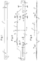
- the bar 1 consisting of a flat profile can be seen, which together with the angular profile shown in FIGS. 2 and 3 two an angular Holding piece for aligning and fastening a door leaf 10 to an appliance door 33 forms.
- the strip 1 consists of a section of flat steel, in the end regions there are elongated holes 3, 4. At a distance from slots 3 and 4 the bar 1 is provided with threaded holes 5, 6.
- the angle profile 2 is bent from a sheet metal blank and has a wider one Leg and an upper narrow leg 8.
- the wider leg 7 is in cutouts on its upper side, the narrower Leg 8 is bent from the center piece formed by the cutouts.
- the wider leg 7 has holes 9 for fastening screws in its end regions through which this can be seen on the inside of FIG. 9 Door leaf can be screwed on.
- the ends of the leg 7 tapered by the cutouts are longitudinally extending Beads 11 stiffened.
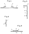
- the angle profile 7 is symmetrical to its transverse center line 12. Both sides of the Transverse center line 12 are tongues 13 bent in opposite directions from leg 7 bent out. These form guides for linearly displaceably guided therein Gauges 14, the cross section of which can be seen in FIG. 8.
- the teachings point 8 has a double Z-shaped cross section.
- the gauges 14 in gap-shaped openings 15 of the upper narrow leg 8 led.
- a leg 7 further tongue 16 bent out in the manner shown in Fig. 8 in the middle groove of teaching 14 engages.
- the teaching 14 is in the manner in the guides 13, 15 and 16 out that it is movable against a resistance in this fixes the currently set position of the teaching.
- the bar 1 is with the upper leg 8 of the angle profile 2 to form the Screwed part.
- a screw 20 in the threaded bore 5 Bar 1 screwed in When screws 20 are loosened, the strip 1 is relative to the leg 8 for adjusting the door leaf in the depth of the built-in device adjustable.
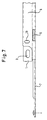
- the leg 8 has lateral cutouts in the manner shown in FIG. 7 on, which release the elongated holes 3 of the bar.
- the elongated holes 3 are in the narrow top 22 of the appliance door 23 screwed or fastened bolts 24 placed until it is screwed onto the lower on the screw bolts 24 Nuts 25 rest.
- the bar 1 to the screw bolt 24 is screwed onto this nut 26. If the nut 26 is loosened, move the holding piece 2 for the side adjustment of the door leaf in the elongated holes 3. To adjust the height of the door leaf, the nut 25 can be adjusted accordingly screwed down or up. After fine adjustment of the door leaf the screws 20 and 26 are tightened.
- an angular profile piece 30 can be seen, one of which Leg 31 can be screwed to one of the lower narrow side areas 33 of the appliance door is and the other leg 34 thereby clamping on the door leaf 10 is held that it is covered by a flat profile piece 35, the End areas are screwed to the door leaf 10.
- the two mutually perpendicular legs 31, 34 of the angular Profile piece 30 are together by an approximately S-shaped section 36 connected, which, in the assembled state, makes it possible for the flat strip-shaped profile 35 formed holding part in the one shown in FIG. 12 Way can extend under the appliance door 23.
- the leg 31 is with a transversely in the narrow side 33 of the appliance door extending slot 37 provide the receiving a fastening screw serves and the setting of the width of the gap between the appliance door 23 and the door leaf 12 allows.
- the flat profile piece 35 is between its mounting holes 38 with a section 40 bent out by means of counter-bent portions 39, the one adapted to the thickness of the leg 34 to the lateral distance the mounting holes provided mounting pieces.
- the angular profile piece 30 is in the flat state of the flat profile piece 35 separated by a U-shaped punch 42.
- the side connecting strips 41 bent in an S-shape so that they form flexible connecting strips, the leg of the angular profile piece covered by the flat profile piece 35 30 allow the necessary mobility.
- the mounting brackets are not only suitable for fixing door leaves to appliance doors, but also to connect other plate-shaped parts together.
Landscapes
- Engineering & Computer Science (AREA)
- Mechanical Engineering (AREA)
- Chemical & Material Sciences (AREA)
- Sustainable Development (AREA)
- Combustion & Propulsion (AREA)
- Physics & Mathematics (AREA)
- Life Sciences & Earth Sciences (AREA)
- Thermal Sciences (AREA)
- General Engineering & Computer Science (AREA)
- Furniture Connections (AREA)
- Securing Of Glass Panes Or The Like (AREA)
- Hinges (AREA)
- Specific Sealing Or Ventilating Devices For Doors And Windows (AREA)
Abstract
Description
- Fig. 1
- eine Draufsicht auf eine aus einem flachen Profil bestehende Leiste,
- Fig. 2
- eine Draufsicht auf den breiteren Schenkel eines Winkelprofil,
- Fig. 3
- eine Oberansicht des Winkelprofils in Richtung des Pfeils A in Fig. 2,
- Fig. 4
- einen Schnitt durch den breiteren Schenkel des Winkelprofils längs der Linie A - A in Fig. 2
- Fig. 5
- einen Schnitt durch das Winkelprofil längs der Linie B - B in Fig. 2
- Fig. 6
- einen Schnitt durch das Winkelprofil längs der Linie D - D in Fig. 2
- Fig. 7
- eine der Fig. 3 entsprechende Darstellung des Winkelprofils, in der der obere schmale Schenkel die Leiste nach Fig. 1 teilweise überdeckt,
- Fig. 8
- einen der Fig. 4 entsprechenden Schnitt mit einer in der durch die abgekröpften Zungen gebildeten Führung geführten Lehre,
- Fig. 9
- einen Schnitt durch das an der Gerätetür gehalterte winkelige Haltestück mit dem den breiteren Schenkel des winkeligen Profils befestigten Türblatt,
- Fig. 10
- einen Schnitt durch das winkelige Profil und die mit dessen oberen schmalen Schenkel verschraubte Leiste,
- Fig. 11
- eine Seitenansicht des den unteren Endbereich des Türblatts an der Gerätetür befestigenden Winkelprofils,
- Fig. 12
- eine Ansicht des Winkelprofils in Richtung des Pfeils B in Fig. 11,
- Fig. 13
- eine Ansicht des Winkelprofils in Richtung des Pfeils A in Fig. 11
- Fig. 14 a und b
- zwei Ansichten des Winkelprofil,
- Fig. 15 a und b
- zwei Ansichten des den einen Schenkel des Winkelprofils festklemmenden flachen Profilstreifens,
- Fig. 16 bis 18
- den Fig. 11 bis 13 entsprechende Darstellungen einer zweiten Ausführungsform des Winkelprofils, das durch seitliche Stege mit dem flachen Profil verbunden ist, und
- Fig. 19
- einen flachliegenden Zuschnitt, aus dem das durch seitliche Stege mit dem flachen Profil verbundene Winkelprofil gebogen ist.
Claims (13)
- Verfahren zum Ausrichten und Befestigen eines Türblatts (10) an einer Gerätetür (23) eines Einbaugeräts, beispielsweise eines Kühl- oder Gefrierschranks,
dadurch gekennzeichnet,daß auf die Oberseite (22) der Gerätetür (23) des in seiner Einbaustellung befindlichen Einbaugeräts ein oberer Schenkel (1, 8) eines winkeligen Haltestücks (1, 2) in der Weise provisorisch festgelegt wird, daß dessen anderer Schenkel (7) parallel zur Vorderseite der Gerätetür (23) liegt,daß in zueinander und zu den Seitenkanten parallelen Führungen (13, 15) des anderen Schenkels (7) kraftschlüssig geführte linealförmige Lehren (14) so weit ausgeschoben werden, daß sie an die Unterkanten des darüber befindlichen Türblatts oder Möbelteils anstoßen,daß das winkelige Haltestück (1, 2) sodann von der Gerätetür (23) abgenommen und nach bündiger Ausrichtung der oberen Enden der Lehren (16) an der Oberseite des Türblatts (10) mit seinem zu der Gerätetür (23) parallelen Schenkel (7) an die Innenseite des Türblatts (10) angeschraubt wird,daß anschließend der obere, mit Justiereinrichtungen versehene Schenkel (1, 8) des winkeligen Haltestücks (1, 2) an die Oberseite (22) der Gerätetür (23) befestigt und das Türblatt (10) durch Betätigung der Justiereinrichtungen ausgerichtet und der obere Schenkel (8, 1) fest mit der Oberseite (23) der Gerätetür (23) verbunden wird. - Verfahren nach Anspruch 1, dadurch gekennzeichnet, daß die Lehren (14) abgewinkelte obere Enden aufweisen und soweit ausgeschoben werden, daß sie mit den Oberseiten ihrer Abwinkelungen die Unterseite des darüber befindlichen Türblatts der Möbelteils anstoßen.
- Vorrichtung zur Durchführung des Verfahrens nach Anspruch 1 oder 2,
dadurch gekennzeichnet,daß ein winkeliges Haltestück (1, 2) vorgesehen ist, dessen oberer Schenkel aus einer Leiste (1) mit flachem Profil besteht, das mit ersten Langlöchern (3) zur Befestigung auf von der Oberseite (22) der Gerätetür (23) aufragenden Schraubbolzen (24) versehen ist und das mit Schraubbolzen (20) versehen ist, die rechtwinkelig zu den ersten Langlöchern (3) verlaufende zweite Langlöcher (19) des oberen schmalen Schenkels (8) eines winkeligen Profils (2) durchsetzen,daß der breitere Schenkel (7) des Winkelprofils (2) mit Bohrungen (9) für Befestigungsschrauben zur Befestigung an dem Türblatt (10) der Vorbautür versehen ist unddaß der breitere Schenkel (7) mit Führungen (13, 15) für linealförmige Lehren (14) versehen ist. - Vorrichtung nach Anspruch 3, dadurch gekennzeichnet, daß die Lehren (14) aus geraden Profilstücken mit abgewinkelten oberen Enden bestehen.
- Vorrichtung nach Anspruch 3 oder 4, dadurch gekennzeichnet, daß die die Oberseite (22) der Gerätetür (23) eingeschraubten Schraubbolzen (24) frei auslaufende Gewinde aufweisen, auf die Muttern (25, 26) aufschraubbar sind, zwischen denen das flache Profil (1) festgelegt ist.
- Vorrichtung nach einem der Ansprüche 3 bis 5, dadurch gekennzeichnet, daß das flache Profil (1) mit Gewindebohrungen (5) versehen ist, in die die Langlöcher (19) des oberen schmalen Schenkels (8) des Winkelprofils (2) durchsetzende Schrauben (20) einschraubbar sind.
- Vorrichtung nach einem der Ansprüche 3 bis 6, dadurch gekennzeichnet, daß die Führungen (13, 15) für die Lehren (14) aus einander gegenüberliegenden, aus den breiten Schenkeln (7) des Winkelprofils (2) herausgebogenen Zungen, die gegensinnig abgepfröpft sind, und aus einem spaltförmigen Durchbruch (15) des oberen schmalen Schenkels (8) bestehen.
- Vorrichtung zur Befestigung des unteren Teils eines Türblatts (10) an einer Gerätetür (23),
gekennzeichnet durch ein winkeliges Profilstück (30), dessen einer mit einem Langloch (37) versehener Schenkel (31) mit der schmalen Außenseite (33) der Gerätetür (23) verschraubbar und dessen anderer Schenkel (34) klemmend durch ein dieses überdeckendes flaches und mit seinen Endbereichen mit dem Türblatt (10) verschraubbares Profilstück (35) mit dem Türblatt (10) verbindbar ist. - Vorrichtung nach Anspruch 8, dadurch gekennzeichnet, daß sich das Langloch (37) quer zur schmalen Außenseite (33) der Gerätetür (23) erstreckt.
- Vorrichtung nach Anspruch 8 oder 9, dadurch gekennzeichnet, daß die Schenkel des winkeligen Profils durch ein etwa S-förmig gekrümmtes Profilstück (36) miteinander verbunden sind.
- Vorrichtung nach einem der Ansprüche 8 bis 10, dadurch gekennzeichnet, daß das flache Profilstück (35) zwischen seinen endseitigen Befestigungsbohrungen (38) mit einem durch gegensinnige Abkröpfungen (39) herausgebogenen Abschnitt (40) versehen ist.
- Vorrichtung nach einem der Ansprüche 8 bis 11, dadurch gekennzeichnet, daß das winkelige und das flache Profilstück (30, 35) zusammenhängend aus einem mit einer U-förmigen Ausstanzung (42) versehenen Blechzuschnitt gebogen sind, in dem vor dem Biegen des winkeligen Profils die Profile durch seitliche, parallel zu dem winkeligen Profil und rechtwinkelig auf dem flachen, streifenförmigen Profil (35) stehende Stege (41) verbunden sind.
- Vorrichtung nach Anspruch 12, dadurch gekennzeichnet, daß die Stege (41) im gebogenen Zustand des winkeligen Profilstücks (30) flexible S-förmig gebogene Verbindungsstreifen bilden.
Priority Applications (1)
| Application Number | Priority Date | Filing Date | Title |
|---|---|---|---|
| EP02015113A EP1245916B1 (de) | 1997-11-04 | 1998-07-22 | Befestigung eines Türblatts an einer Gerätetür |
Applications Claiming Priority (2)
| Application Number | Priority Date | Filing Date | Title |
|---|---|---|---|
| DE19748679A DE19748679C1 (de) | 1997-11-04 | 1997-11-04 | Befestigung eines Türblatts an einer Gerätetür |
| DE19748679 | 1997-11-04 |
Related Child Applications (1)
| Application Number | Title | Priority Date | Filing Date |
|---|---|---|---|
| EP02015113A Division EP1245916B1 (de) | 1997-11-04 | 1998-07-22 | Befestigung eines Türblatts an einer Gerätetür |
Publications (3)
| Publication Number | Publication Date |
|---|---|
| EP0915310A2 true EP0915310A2 (de) | 1999-05-12 |
| EP0915310A3 EP0915310A3 (de) | 2000-05-03 |
| EP0915310B1 EP0915310B1 (de) | 2003-02-26 |
Family
ID=7847572
Family Applications (2)
| Application Number | Title | Priority Date | Filing Date |
|---|---|---|---|
| EP98113677A Expired - Lifetime EP0915310B1 (de) | 1997-11-04 | 1998-07-22 | Befestigung eines Türblatts an einer Gerätetür |
| EP02015113A Expired - Lifetime EP1245916B1 (de) | 1997-11-04 | 1998-07-22 | Befestigung eines Türblatts an einer Gerätetür |
Family Applications After (1)
| Application Number | Title | Priority Date | Filing Date |
|---|---|---|---|
| EP02015113A Expired - Lifetime EP1245916B1 (de) | 1997-11-04 | 1998-07-22 | Befestigung eines Türblatts an einer Gerätetür |
Country Status (3)
| Country | Link |
|---|---|
| EP (2) | EP0915310B1 (de) |
| DE (3) | DE19748679C1 (de) |
| ES (2) | ES2238524T3 (de) |
Cited By (4)
| Publication number | Priority date | Publication date | Assignee | Title |
|---|---|---|---|---|
| WO2009127570A1 (de) * | 2008-04-17 | 2009-10-22 | BSH Bosch und Siemens Hausgeräte GmbH | Beschlagaufbau und verfahren zur höhenrichtigen montage einer dekorplatte an einer tür eines haushaltsgeräts |
| DE102012205075A1 (de) | 2012-03-29 | 2013-10-02 | BSH Bosch und Siemens Hausgeräte GmbH | Montagehilfsvorrichtung und Haushaltsgerät, insbesondere Haushaltskältegerät mit einer solchen Montagehilfsvorrichtung |
| EP2664879A2 (de) | 2012-05-16 | 2013-11-20 | BSH Bosch und Siemens Hausgeräte GmbH | Vorrichtung zum Positionieren eines Befestigungselements sowie ein Verfahren zur Montage eines Befestigungselements an einer Möbelfront |
| DE102012208260A1 (de) | 2012-05-16 | 2013-11-21 | BSH Bosch und Siemens Hausgeräte GmbH | Vorrichtung zum Positionieren eines Befestigungselements sowie ein Verfahren zur Montage eines Befestigungselements an einer Möbelfront |
Families Citing this family (16)
| Publication number | Priority date | Publication date | Assignee | Title |
|---|---|---|---|---|
| IT251731Y1 (it) | 2000-04-11 | 2004-01-20 | Electrolux Zanussi Elettrodome | Staffa perfezionata per porta di frigorifero da incasso |
| KR100512734B1 (ko) * | 2003-05-10 | 2005-09-07 | 삼성전자주식회사 | 빌트인 저장고 |
| DE102005021534A1 (de) * | 2005-05-10 | 2006-11-23 | BSH Bosch und Siemens Hausgeräte GmbH | Tür für ein Haushaltsgerät |
| DE102005021607A1 (de) | 2005-05-10 | 2006-11-23 | BSH Bosch und Siemens Hausgeräte GmbH | Tür für ein Haushaltsgerät |
| DE102005021563A1 (de) * | 2005-05-10 | 2006-11-16 | BSH Bosch und Siemens Hausgeräte GmbH | Justierschiene |
| DE102006018420A1 (de) * | 2006-04-20 | 2007-10-25 | BSH Bosch und Siemens Hausgeräte GmbH | Anordnung zum Befestigen einer Möbelfront |
| DE102007021554A1 (de) * | 2007-05-08 | 2008-11-13 | BSH Bosch und Siemens Hausgeräte GmbH | Haushaltsgerät |
| DE102007021553A1 (de) * | 2007-05-08 | 2008-11-13 | BSH Bosch und Siemens Hausgeräte GmbH | Einbau-Haushaltsgerät |
| DE202008005332U1 (de) * | 2008-04-17 | 2008-09-18 | BSH Bosch und Siemens Hausgeräte GmbH | Haushaltsgerät mit Klemmschutz |
| DE202008005406U1 (de) * | 2008-04-18 | 2008-09-04 | BSH Bosch und Siemens Hausgeräte GmbH | Beschlagaufbau zur höhenrichtigen Montage einer Dekorplatte an einer Tür eines Haushaltsgeräts |
| DE102009036851A1 (de) | 2009-05-29 | 2010-12-02 | Liebherr-Hausgeräte Ochsenhausen GmbH | Türsystem für ein Kühl- und/oder Gefriergerät, Kühl- und/oder Gefriergerät sowie Verfahren zur Montage eines Türsystems |
| DE102009036845A1 (de) | 2009-05-29 | 2010-12-02 | Liebherr-Hausgeräte Ochsenhausen GmbH | Türsystem für ein Kühl- und/oder Gefriergerät, Kühl- und/oder Gefriergerät sowie Verfahren zur Montage eines Türsystems |
| DE102014225088B4 (de) | 2014-12-08 | 2025-05-28 | BSH Hausgeräte GmbH | Verfahren zum Montieren einer Schleppvorrichtung |
| DE102017222329B3 (de) | 2017-12-11 | 2019-04-18 | Norbert Fischer | Verfahren zum Montieren einer Möbelfront an einer Einbaugerätetüre und Montagevorrichtung hierfür |
| CN111021894B (zh) * | 2019-11-13 | 2021-09-07 | 陕西迈拓克能源科技有限公司 | 一种用于厨房门板的校准装置 |
| CN113865231B (zh) | 2020-06-30 | 2023-07-14 | 青岛海尔电冰箱有限公司 | 可更换门面的冰箱门 |
Citations (1)
| Publication number | Priority date | Publication date | Assignee | Title |
|---|---|---|---|---|
| DE4443852C1 (de) | 1994-10-25 | 1995-12-07 | Bauknecht Hausgeraete | Verfahren und Vorrichtung zum Anbringen eines Türblattes an der Gerätetür eines eingebauten Haushalt-Einbaugerätes |
Family Cites Families (6)
| Publication number | Priority date | Publication date | Assignee | Title |
|---|---|---|---|---|
| DE2922384C2 (de) * | 1979-06-01 | 1984-02-23 | Bosch-Siemens Hausgeräte GmbH, 7000 Stuttgart | In eine Einbaunische eines Küchen-Hochschrankes o.dgl., einsetzbares Einbaugerät, insbesondere Kühl- oder Gefrierschrank |
| FR2535800B1 (fr) * | 1982-11-05 | 1986-04-11 | Thomson Brandt | Dispositif de fixation et de reglage en position de panneaux d'habillage de portes et portes d'armoires frigorifiques integrables munies de panneaux fixes par ce dispositif |
| DE8420711U1 (de) * | 1984-07-11 | 1985-08-29 | Prämeta Präzisionsmetall- und Kunststofferzeugnisse G. Baumann & Co, 5000 Köln | Befestigungsvorrichtung für eine Dekorplatte an der Gerätetür eines Einbaukühlschrankes |
| FR2671467B1 (fr) * | 1991-01-11 | 1993-06-18 | Dietrich Equip Menager | Interface de rattrapage du deport lateral entre la porte d'un appareil electromenager et celle du meuble-element qui le contient. |
| DE9313205U1 (de) * | 1993-09-02 | 1995-01-05 | Licentia Patent-Verwaltungs-Gmbh, 60596 Frankfurt | Vorsatzplatten-Ausgleich für Haushalt-Einbaugeräte |
| DE4334761A1 (de) * | 1993-10-12 | 1995-04-13 | Bosch Siemens Hausgeraete | Haushaltsgerät zum Einbau in eine Möbelnische einer Küchenzeile oder dergleichen |
-
1997
- 1997-11-04 DE DE19748679A patent/DE19748679C1/de not_active Expired - Fee Related
-
1998
- 1998-07-22 ES ES02015113T patent/ES2238524T3/es not_active Expired - Lifetime
- 1998-07-22 ES ES98113677T patent/ES2193446T3/es not_active Expired - Lifetime
- 1998-07-22 DE DE59812665T patent/DE59812665D1/de not_active Expired - Lifetime
- 1998-07-22 EP EP98113677A patent/EP0915310B1/de not_active Expired - Lifetime
- 1998-07-22 EP EP02015113A patent/EP1245916B1/de not_active Expired - Lifetime
- 1998-07-22 DE DE59807297T patent/DE59807297D1/de not_active Expired - Lifetime
Patent Citations (1)
| Publication number | Priority date | Publication date | Assignee | Title |
|---|---|---|---|---|
| DE4443852C1 (de) | 1994-10-25 | 1995-12-07 | Bauknecht Hausgeraete | Verfahren und Vorrichtung zum Anbringen eines Türblattes an der Gerätetür eines eingebauten Haushalt-Einbaugerätes |
Cited By (5)
| Publication number | Priority date | Publication date | Assignee | Title |
|---|---|---|---|---|
| WO2009127570A1 (de) * | 2008-04-17 | 2009-10-22 | BSH Bosch und Siemens Hausgeräte GmbH | Beschlagaufbau und verfahren zur höhenrichtigen montage einer dekorplatte an einer tür eines haushaltsgeräts |
| DE102012205075A1 (de) | 2012-03-29 | 2013-10-02 | BSH Bosch und Siemens Hausgeräte GmbH | Montagehilfsvorrichtung und Haushaltsgerät, insbesondere Haushaltskältegerät mit einer solchen Montagehilfsvorrichtung |
| EP2664879A2 (de) | 2012-05-16 | 2013-11-20 | BSH Bosch und Siemens Hausgeräte GmbH | Vorrichtung zum Positionieren eines Befestigungselements sowie ein Verfahren zur Montage eines Befestigungselements an einer Möbelfront |
| DE102012208258A1 (de) | 2012-05-16 | 2013-11-21 | BSH Bosch und Siemens Hausgeräte GmbH | Vorrichtung zum Positionieren eines Befestigungselements sowie ein Verfahren zur Montage eines Befestigungselements an einer Möbelfront |
| DE102012208260A1 (de) | 2012-05-16 | 2013-11-21 | BSH Bosch und Siemens Hausgeräte GmbH | Vorrichtung zum Positionieren eines Befestigungselements sowie ein Verfahren zur Montage eines Befestigungselements an einer Möbelfront |
Also Published As
| Publication number | Publication date |
|---|---|
| ES2193446T3 (es) | 2003-11-01 |
| EP1245916A3 (de) | 2002-10-16 |
| EP1245916B1 (de) | 2005-03-16 |
| EP0915310B1 (de) | 2003-02-26 |
| ES2238524T3 (es) | 2005-09-01 |
| DE59807297D1 (de) | 2003-04-03 |
| EP0915310A3 (de) | 2000-05-03 |
| DE19748679C1 (de) | 1998-11-26 |
| EP1245916A2 (de) | 2002-10-02 |
| DE59812665D1 (de) | 2005-04-21 |
Similar Documents
| Publication | Publication Date | Title |
|---|---|---|
| EP0915310B1 (de) | Befestigung eines Türblatts an einer Gerätetür | |
| DE202005006528U1 (de) | Befestigungsprofil | |
| CH663983A5 (de) | Treibstangenbeschlag fuer fenster oder tueren. | |
| DE69824076T2 (de) | Befestigungssystem für Platten, insbesondere Platten für belüftete Fassaden | |
| EP1439269B1 (de) | Verbinder für die Befestigung von Montageprofilen der Sanitärtechnik sowie Traggestell mit einem solchen Verbinder | |
| DE2923903C2 (de) | ||
| DE2703060A1 (de) | Einstellbare aufhaengung fuer tore o.dgl. | |
| DE4345103C2 (de) | Vorrichtung zur Befestigung von winkeligen Installationselementen | |
| AT403242B (de) | Befestigung für eine duschkabine an einer wand | |
| EP1318261A2 (de) | Befestigungsvorrichtung | |
| EP0033904B1 (de) | Metallklammer für Wand- und Deckenverkleidungen | |
| DE602004003430T2 (de) | Vorrichtung zur Befestigung eines Bandes an einem Flügel | |
| EP0609973B1 (de) | Vorrichtung zur Befestigung von Deckenwinkeln | |
| EP0201056A2 (de) | Zarge | |
| DE4327411C2 (de) | Profilteil mit einer in Gleitnuten verschiebbar angeordneten Kralle | |
| DE3527239C2 (de) | ||
| DE3523741C2 (de) | Tragkonstruktion für abgehängte Decken | |
| DE9301520U1 (de) | Vorrichtung zur Befestigung von Installationselementen | |
| DE2701957B2 (de) | Führung für Schrankschiebetüren | |
| DE9404038U1 (de) | Variables Winkelelement | |
| EP3763260B1 (de) | Befestigungsvorrichtung für eine duschtrennwand | |
| EP0822302A1 (de) | Verteilerschrank für Sanitär- und/oder Heizungsinstallationen | |
| EP1057436B1 (de) | Vorrichtung zum Befestigen einer Blende für Lamellenstoren | |
| DE20009333U1 (de) | Holzwandteil | |
| DE19734647A1 (de) | Beschlagteil an einem Flügel oder einem festen Rahmen eines Fensters, einer Tür od. dgl. |
Legal Events
| Date | Code | Title | Description |
|---|---|---|---|
| PUAI | Public reference made under article 153(3) epc to a published international application that has entered the european phase |
Free format text: ORIGINAL CODE: 0009012 |
|
| AK | Designated contracting states |
Kind code of ref document: A2 Designated state(s): DE ES FR GB IT SE |
|
| AX | Request for extension of the european patent |
Free format text: AL;LT;LV;MK;RO;SI |
|
| K1C1 | Correction of patent application (title page) published |
Effective date: 19990512 |
|
| PUAL | Search report despatched |
Free format text: ORIGINAL CODE: 0009013 |
|
| AK | Designated contracting states |
Kind code of ref document: A3 Designated state(s): AT BE CH CY DE DK ES FI FR GB GR IE IT LI LU MC NL PT SE |
|
| AX | Request for extension of the european patent |
Free format text: AL;LT;LV;MK;RO;SI |
|
| 17P | Request for examination filed |
Effective date: 20000403 |
|
| AKX | Designation fees paid |
Free format text: DE ES FR GB IT SE |
|
| 17Q | First examination report despatched |
Effective date: 20020308 |
|
| GRAH | Despatch of communication of intention to grant a patent |
Free format text: ORIGINAL CODE: EPIDOS IGRA |
|
| GRAH | Despatch of communication of intention to grant a patent |
Free format text: ORIGINAL CODE: EPIDOS IGRA |
|
| GRAA | (expected) grant |
Free format text: ORIGINAL CODE: 0009210 |
|
| AK | Designated contracting states |
Designated state(s): DE ES FR GB IT SE |
|
| PG25 | Lapsed in a contracting state [announced via postgrant information from national office to epo] |
Ref country code: GB Free format text: LAPSE BECAUSE OF FAILURE TO SUBMIT A TRANSLATION OF THE DESCRIPTION OR TO PAY THE FEE WITHIN THE PRESCRIBED TIME-LIMIT Effective date: 20030226 |
|
| REG | Reference to a national code |
Ref country code: GB Ref legal event code: FG4D Free format text: NOT ENGLISH |
|
| REF | Corresponds to: |
Ref document number: 59807297 Country of ref document: DE Date of ref document: 20030403 Kind code of ref document: P |
|
| RAP2 | Party data changed (patent owner data changed or rights of a patent transferred) |
Owner name: LIEBHERR-HAUSGERAETE OCHSENHAUSEN GMBH |
|
| PG25 | Lapsed in a contracting state [announced via postgrant information from national office to epo] |
Ref country code: SE Free format text: LAPSE BECAUSE OF FAILURE TO SUBMIT A TRANSLATION OF THE DESCRIPTION OR TO PAY THE FEE WITHIN THE PRESCRIBED TIME-LIMIT Effective date: 20030526 |
|
| GBV | Gb: ep patent (uk) treated as always having been void in accordance with gb section 77(7)/1977 [no translation filed] |
Effective date: 20030226 |
|
| REG | Reference to a national code |
Ref country code: ES Ref legal event code: FG2A Ref document number: 2193446 Country of ref document: ES Kind code of ref document: T3 |
|
| ET | Fr: translation filed | ||
| PLBE | No opposition filed within time limit |
Free format text: ORIGINAL CODE: 0009261 |
|
| STAA | Information on the status of an ep patent application or granted ep patent |
Free format text: STATUS: NO OPPOSITION FILED WITHIN TIME LIMIT |
|
| 26N | No opposition filed |
Effective date: 20031127 |
|
| PGFP | Annual fee paid to national office [announced via postgrant information from national office to epo] |
Ref country code: ES Payment date: 20130704 Year of fee payment: 16 |
|
| PGFP | Annual fee paid to national office [announced via postgrant information from national office to epo] |
Ref country code: FR Payment date: 20130719 Year of fee payment: 16 |
|
| PGFP | Annual fee paid to national office [announced via postgrant information from national office to epo] |
Ref country code: IT Payment date: 20130725 Year of fee payment: 16 |
|
| REG | Reference to a national code |
Ref country code: FR Ref legal event code: ST Effective date: 20150331 |
|
| PG25 | Lapsed in a contracting state [announced via postgrant information from national office to epo] |
Ref country code: IT Free format text: LAPSE BECAUSE OF NON-PAYMENT OF DUE FEES Effective date: 20140722 |
|
| PG25 | Lapsed in a contracting state [announced via postgrant information from national office to epo] |
Ref country code: FR Free format text: LAPSE BECAUSE OF NON-PAYMENT OF DUE FEES Effective date: 20140731 |
|
| REG | Reference to a national code |
Ref country code: ES Ref legal event code: FD2A Effective date: 20150827 |
|
| PG25 | Lapsed in a contracting state [announced via postgrant information from national office to epo] |
Ref country code: ES Free format text: LAPSE BECAUSE OF NON-PAYMENT OF DUE FEES Effective date: 20140723 |
|
| PGFP | Annual fee paid to national office [announced via postgrant information from national office to epo] |
Ref country code: DE Payment date: 20170727 Year of fee payment: 20 |
|
| REG | Reference to a national code |
Ref country code: DE Ref legal event code: R071 Ref document number: 59807297 Country of ref document: DE |