EP0917755B1 - Kommutierungsvorrichtung für gleichstrommotor - Google Patents
Kommutierungsvorrichtung für gleichstrommotor Download PDFInfo
- Publication number
- EP0917755B1 EP0917755B1 EP97929125A EP97929125A EP0917755B1 EP 0917755 B1 EP0917755 B1 EP 0917755B1 EP 97929125 A EP97929125 A EP 97929125A EP 97929125 A EP97929125 A EP 97929125A EP 0917755 B1 EP0917755 B1 EP 0917755B1
- Authority
- EP
- European Patent Office
- Prior art keywords
- commutator
- contact surface
- longitudinal edge
- angle
- brushes
- Prior art date
- Legal status (The legal status is an assumption and is not a legal conclusion. Google has not performed a legal analysis and makes no representation as to the accuracy of the status listed.)
- Expired - Lifetime
Links
- 230000001747 exhibiting effect Effects 0.000 claims 1
- 241000446313 Lamella Species 0.000 description 8
- 238000013461 design Methods 0.000 description 5
- 238000011156 evaluation Methods 0.000 description 5
- 238000000034 method Methods 0.000 description 5
- 238000011161 development Methods 0.000 description 3
- 230000018109 developmental process Effects 0.000 description 3
- 238000010586 diagram Methods 0.000 description 3
- 238000013459 approach Methods 0.000 description 1
- 230000001680 brushing effect Effects 0.000 description 1
- 238000001514 detection method Methods 0.000 description 1
- 230000000694 effects Effects 0.000 description 1
- 230000005284 excitation Effects 0.000 description 1
- 238000000605 extraction Methods 0.000 description 1
- 238000004519 manufacturing process Methods 0.000 description 1
- 230000002123 temporal effect Effects 0.000 description 1
Images

Classifications
-
- H—ELECTRICITY
- H02—GENERATION; CONVERSION OR DISTRIBUTION OF ELECTRIC POWER
- H02K—DYNAMO-ELECTRIC MACHINES
- H02K13/00—Structural associations of current collectors with motors or generators, e.g. brush mounting plates or connections to windings; Disposition of current collectors in motors or generators; Arrangements for improving commutation
- H02K13/10—Arrangements of brushes or commutators specially adapted for improving commutation
Definitions
- the invention is based on a commutation device a DC motor, consisting among other things out Collector blades and brushes, according to the generic term of Main claim where the ripple of the current with the help an electronic circuit is detectable and as a measure for the speed or the number of engine revolutions can be evaluated is.
- a disadvantage of these arrangements is that Brushing noise, which arises from the fact that the Run the collector slats suddenly under the brush.
- the Brush noise is defined in a manner known per se, than the resulting airborne sound, which with a Microphone can be measured.
- the brush tread according to DE-A-31 48 966 run Collector slats even twice per brush under Brush tread. The noise development is still here stronger.
- US-A-5 049 772 and DE-A-417 833 describe one Device for preventing brushes fire and electrical losses and to eliminate Noises.
- the commutation device according to the main claim to consider that the commutation process takes longer lasts because two adjacent collector slats from the contact surface of the brush with the commutator a larger range of rotation of the armature of the DC motor are short-circuited.
- Noise from the engine is lower because of the Torque ripple less within one armature revolution and the electromagnetic excitation of the motor housing becomes lower. This noise development corresponds to that so-called structure-borne noise, which is in the form of vibrations is measured.
- Another advantage of this solution is that reduced brush noise. Because of the inventive Design of the commutation device run the Collector fins not suddenly (at one time) under the brush but gradually or continuously.
- the brush tread after registration DE-A-31 48 966 in which the brush two Has contact surfaces to the commutator and therefore each Collector lamella twice per brush under a contact surface runs, the brush sound through the inventive Design of the commutation device significantly improved and the noise pollution can be reduced.
- Figure 1 shows schematically in spatial representation a commutator 10 of a DC motor, constructed from Collector lamellae 11 arranged next to one another on the circumference and insulating slats in between. 12.
- the commutator 10 rotates in the direction of the arrow about an axis 13, parallel to this axis 13 is an imaginary straight line 14 in the cylindrical surface of the commutator 10.
- This imaginary Line 14 parallel to the axis overlaps with a front line Longitudinal edge 18 of a contact surface 16 of a brush with the Commutator 10.
- the longitudinal edge 18 closes with each of the Longitudinal edges of the collector slats 11 an angle ⁇ of z. B. ten degrees.
- Schematic on the surface of the Commutator 10 is the contact surface 16 of the brush marked with a corresponding opposite, not recognizable second brush cooperates.
- the commutator 10 is rotationally symmetrical axis 13.
- the commutator rotates when the DC motor is operating 10 under the contact surface 16.
- the collector lamella 11b is through the contact surface 16 with its neighboring Collector lamella 11c short-circuited.
- commutator 10 has so much less the contact surface 16 of the brush rotated that the Collector lamella 11b no longer with that adjacent to it Collector lamella 11c is short-circuited, but with the next adjacent collector lamella 11a.
- FIG. 2 schematically shows a spatial view Commutator 20, made up of the collector bars 21a, b, c ... which has a bulge in the middle area Have circumferential direction and against each other by the Insulating lamellae 22a, b, ... are insulated.
- the commutator 20 rotates about its axis 23 in the direction of the arrow Commutator surface lies an imaginary, arbitrary axially parallel straight line 24, which is again aligned with the front Longitudinal edge 28 of a contact surface 26 covers.
- This Longitudinal edge 28 closes with a tangent 25 of the bulge at the collector lamella 21 at the intersection of the front Longitudinal edge 28 with the longitudinal edge of the collector plate 21 den Angle ⁇ of approximately one hundred and twenty degrees.
- the Collector fins 21 can also be ⁇ -shaped in the Commutator surface be curved in the direction of rotation, then the angle ⁇ in the amount between zero and can vary a hundred and eighty degrees.
- Figure 3 schematically shows a spatial view Commutator 30, which is composed of axially parallel collector fins 31 is constructed.
- the commutator 30 rotates in the direction of the arrow about an axis 33 under a contact surface 36 of a brush away, the front longitudinal edge 38 at the angle ⁇ of ten Degree to the collector lamella 32 stands, the longitudinal edge of which covered with the axially parallel straight line 34.
- the angle ⁇ , the width of the collector slats 11, 21, 31 and the shape of the contact surface 16, 26, 36 must be in each Embodiment are so coordinated that constantly at least two collector lamellae 11, 21, 31 be short-circuited.
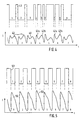
- the lower curve in Figure 4 shows the analog signal of the Commutation current 40 of a DC motor with conventional commutation device (collector plates and the front longitudinal edge of the contact surfaces of the brushes axially parallel) plotted over the time axis t.
- each Pulse 42 has two ripples 42a and b.
- the diagram shows the digital signal curve 43, by means of evaluation electronics known per se from the analog signal of the commutation current was obtained. To It can be seen here that the evaluation electronics erroneously nine impulses instead of the required has captured seven.
- Figure 5 is the analog signal of the commutation current 50 and the digital signal 53 obtained therefrom mechanically commutated DC motor using the commutation device designed according to the invention according to the first exemplary embodiment according to FIG. 1 shown.
- the lower curve corresponds to the analog one Signal course of the commutation current 50 via a Time range that corresponds to eight pulses 52.
- the Ripples are no longer recognizable with this signal curve.
- the evaluation electronics can also be correspondingly reliable capture the analog pulses 52 and convert them into corresponding ones Implement digital impulses, eight in number.
- the brushes are designed in this way can be used instead of a substantially rectangular one or linear contact surface 16, 26, 36 two in essential circular or punctiform contact surfaces exhibit. In this case it corresponds to the angle ⁇ decisive front longitudinal edge 18, 28, 38 of the contact surface the front longitudinal edge of a connecting surface, which the two essentially circular or point-shaped Connects contact areas with each other.
- Commutators 10, 20 which are connected to those of FIGS. 1 and 2 designed collector plates 11, 21 are equipped, could also with the z.
- B. DE-A-31 48 966 executed Brushes are operated.
Landscapes
- Engineering & Computer Science (AREA)
- Power Engineering (AREA)
- Motor Or Generator Current Collectors (AREA)
- Dc Machiner (AREA)
- Control Of Direct Current Motors (AREA)
Description
Claims (5)
- Kommutierungsvorrichtung eines Gleichstrommotors, insbesondere eines mechanisch kommutierten Gleichstrommotors, mit einem Kollektorlamellen (11, 21, 31) aufweisenden Kommutator (10, 20, 30) und mit Bürsten, wobei die Bürsten mit dem Kommutator (10, 20, 30) jeweils eine Kontaktfläche (16, 26, 36) haben und wobei die Welligkeit des Stromes (40, 50), die bei der Kommutierung des Motorstromes entsteht, mit Hilfe einer elektronischen Schaltung erfaßt und die Frequenz der Welligkeit als ein Maß für die Drehzahl ausgewertet ist, dadurch gekennzeichnet, daß zur Gewinnung eindeutiger und fehlerfreier Drehzahlinformationen die Längskante der Kollektorlamellen (11, 21, 31) und die vordere Längskante (18, 28, 38) der Kontaktfläche (16, 26, 36) jeweils mindestens einer der Bürsten zusammen einen Winkel (α) größer null Grad einschließen, so daß mindestens zwei benachbarte Kollektorlamellen (11, 21, 31) ständig über die Bürste kurzgeschlossen sind.
- Kommutierungsvorrichtung nach Anspruch 1, dadurch gekennzeichnet, daß die Längskanten der Kollektorlamellen (11, 21, 31) und/oder die vordere Längskante (18, 28, 38) der Kontaktfläche (16, 26, 36) einen Winkel zu einer gedachten achsparallelen Geraden (14, 24, 34) in der Kommutatoroberfläche bilden, und daß durch die Kontaktfläche (16, 26, 36) mindestens zwei Kollektorlamellen ständig kurzgeschlossen sind.
- Kommutierungsvorrichtung nach Anspruch 2, dadurch gekennzeichnet, daß die vordere Längskante (18) der Kontaktfläche (16) parallel zur gedachten achsparallelen Geraden (14) in der Kommutatoroberfläche liegt und die Längskanten der Kollektorlamellen (11) in einem konstanten Winkel (α) vom Betrag größer null Grad und kleiner fünfundvierzig Grad zu der gedachten achsparallelen Geraden (14) liegen, vorzugsweise in einem Winkel (α) gleich zehn Grad.
- Kommutierungsvorrichtung nach Anspruch 2, dadurch gekennzeichnet, daß die vordere Längskante (28) der Kontaktfläche (26) parallel zur gedachten achsparallelen Geraden (24) liegt und die Längskanten der Kollektorlamellen (21) bereichsweise in der Kommutatoroberfläche in Umfangsrichtung ausgewölbt sind, wobei der Betrag des Winkels (α) im Bereich der Auswölbung zwischen der Tangente (25) an den Kollektorlamellen (21) und der Längskante (28) der Kontaktfläche (26) größer null und kleiner hundertachtzig Grad ist.
- Kommutierungsvorrichtung nach Anspruch 2, dadurch gekennzeichnet, daß die Längskanten der Kollektorlamellen (31) parallel zu einer gedachten achsparallelen Geraden (34) liegen und daß die vordere Längskante (38) der Kontaktfläche (36) jeweils einer der Bürsten mit dem Kommutator (30) in einem konstanten Winkel (α) vom Betrag größer null Grad und kleiner fünfundvierzig Grad zu der gedachten achsparallelen Geraden (14) liegt, vorzugsweise in einem Winkel (α) gleich zehn Grad.
Applications Claiming Priority (3)
| Application Number | Priority Date | Filing Date | Title |
|---|---|---|---|
| DE19631828 | 1996-08-07 | ||
| DE19631828A DE19631828A1 (de) | 1996-08-07 | 1996-08-07 | Kommutierungsvorrichtung für Gleichstrommotor |
| PCT/DE1997/001270 WO1998006163A1 (de) | 1996-08-07 | 1997-06-20 | Kommutierungsvorrichtung für gleichstrommotor |
Publications (2)
| Publication Number | Publication Date |
|---|---|
| EP0917755A1 EP0917755A1 (de) | 1999-05-26 |
| EP0917755B1 true EP0917755B1 (de) | 2001-11-07 |
Family
ID=7801994
Family Applications (1)
| Application Number | Title | Priority Date | Filing Date |
|---|---|---|---|
| EP97929125A Expired - Lifetime EP0917755B1 (de) | 1996-08-07 | 1997-06-20 | Kommutierungsvorrichtung für gleichstrommotor |
Country Status (6)
| Country | Link |
|---|---|
| US (1) | US6288468B1 (de) |
| EP (1) | EP0917755B1 (de) |
| JP (1) | JP2000515717A (de) |
| DE (2) | DE19631828A1 (de) |
| ES (1) | ES2167753T3 (de) |
| WO (1) | WO1998006163A1 (de) |
Cited By (4)
| Publication number | Priority date | Publication date | Assignee | Title |
|---|---|---|---|---|
| DE102007034613A1 (de) | 2007-07-25 | 2009-01-29 | Robert Bosch Gmbh | Elektrische Maschine mit einem Kommutator, sowie Verfahren zum Betreiben der elektrischen Maschine |
| DE102007036253A1 (de) | 2007-08-02 | 2009-02-05 | Robert Bosch Gmbh | Elektrische Maschine mit in Nuten angeordneten Leiterschleifen, sowie Verfahren zum Betreiben der elektrschen Maschine |
| DE102008000624A1 (de) | 2008-03-12 | 2009-09-17 | Robert Bosch Gmbh | Elektrische Maschine mit einem Rotor, sowie Verfahren zum Betreiben der elektrischen Maschine |
| DE102013227134A1 (de) | 2013-12-23 | 2015-06-25 | Robert Bosch Gmbh | Kommutiervorrichtung für eine elektrische Maschine, Rotor, sowie elektrische Maschine mit einer solchen Kommutiervorrichtung |
Families Citing this family (8)
| Publication number | Priority date | Publication date | Assignee | Title |
|---|---|---|---|---|
| DE10126168A1 (de) * | 2001-05-30 | 2002-12-05 | Kostal Leopold Gmbh & Co Kg | Verfahren zum Bestimmen der Frequenz der im Ankerstromsignal eines kommutierten Gleichstrommotors enthaltenen Stromrippel |
| DE10146569A1 (de) * | 2001-09-21 | 2003-04-10 | Bosch Gmbh Robert | Kommutierungsvorrichtung für eine elektrische Maschine |
| CN100435431C (zh) * | 2003-12-12 | 2008-11-19 | 乐金电子(天津)电器有限公司 | 单相直流电动机用整流子的整流子片排列结构 |
| DE102008021071A1 (de) * | 2008-04-26 | 2009-11-05 | Brose Fahrzeugteile Gmbh & Co. Kommanditgesellschaft, Hallstadt | Bürstenanordnung bei einem Elektromotor |
| DE102008033868A1 (de) * | 2008-07-19 | 2010-01-21 | Faurecia Autositze Gmbh | Gleichstrom-Kommutatormotor, insbesondere für eine Fahrzeugsitzverstellung |
| KR101407960B1 (ko) | 2009-09-10 | 2014-06-17 | 삼성전자 주식회사 | 세탁기 및 그 제어방법 |
| DE102014225515A1 (de) * | 2014-12-11 | 2016-06-16 | Robert Bosch Gmbh | Kommutierungseinrichtung für eine elektrische Maschine |
| DE102016222924A1 (de) * | 2016-11-21 | 2018-05-24 | Seg Automotive Germany Gmbh | Kommutierungseinrichtung für eine elektrische Maschine |
Family Cites Families (13)
| Publication number | Priority date | Publication date | Assignee | Title |
|---|---|---|---|---|
| DE417833C (de) | 1925-08-26 | Bbc Brown Boveri & Cie | Einrichtung zur Erzielung eines ruhigen Laufens von Kohlebuersten auf rauhen Kollektoren elektrischer Maschinen | |
| DE581451C (de) | 1927-11-08 | 1933-07-27 | Siemens Schuckertwerke Akt Ges | Einrichtung zum Vermeiden von Buerstengeraeuschen bei Kommutatormaschinen mit wechselnder Drehrichtung, insbesondere bei Bahnmotoren |
| US1861059A (en) * | 1930-04-08 | 1932-05-31 | Carl E Johnson | Rotor for silent motors |
| FR2257162A1 (en) * | 1974-01-04 | 1975-08-01 | Preux Roger | Switch with rotary collector - has metal contact strips on collector inclined w.r.t. collector axis |
| JPS5866865U (ja) | 1981-10-28 | 1983-05-07 | マブチモ−タ−株式会社 | 小型モ−タ |
| US4633153A (en) * | 1986-02-24 | 1986-12-30 | General Motors Corporation | Power window control with tape drive tension release |
| US5049772A (en) * | 1990-09-10 | 1991-09-17 | United Technologies Corporation | Reduced noise commutator |
| GB2256753A (en) | 1991-06-10 | 1992-12-16 | Tse Tak Tung | Roller brushes for an electric motor |
| DE4229045A1 (de) * | 1992-08-29 | 1994-03-03 | Brose Fahrzeugteile | Bürstenbehafteter Kommutatormotor |
| DE4329753A1 (de) * | 1993-09-03 | 1995-03-09 | Teves Gmbh Alfred | Kohlebürste für einen Elektromotor |
| DE4422083A1 (de) | 1994-06-24 | 1996-01-04 | Bosch Gmbh Robert | Verfahren und Einrichtung zur Drehzahlmessung eines mechanisch kommutierten Gleichstrommotors |
| DE4438868C2 (de) * | 1994-11-03 | 2002-01-24 | Bosch Gmbh Robert | Kohlebürste für einen Gleichstrommotor |
| US5910696A (en) * | 1997-12-01 | 1999-06-08 | Ut Automotive Dearborn, Inc. | Reduced noise commutator system |
-
1996
- 1996-08-07 DE DE19631828A patent/DE19631828A1/de not_active Ceased
-
1997
- 1997-06-20 US US09/242,071 patent/US6288468B1/en not_active Expired - Fee Related
- 1997-06-20 ES ES97929125T patent/ES2167753T3/es not_active Expired - Lifetime
- 1997-06-20 JP JP10507441A patent/JP2000515717A/ja not_active Abandoned
- 1997-06-20 EP EP97929125A patent/EP0917755B1/de not_active Expired - Lifetime
- 1997-06-20 WO PCT/DE1997/001270 patent/WO1998006163A1/de not_active Ceased
- 1997-06-20 DE DE59705294T patent/DE59705294D1/de not_active Expired - Fee Related
Cited By (4)
| Publication number | Priority date | Publication date | Assignee | Title |
|---|---|---|---|---|
| DE102007034613A1 (de) | 2007-07-25 | 2009-01-29 | Robert Bosch Gmbh | Elektrische Maschine mit einem Kommutator, sowie Verfahren zum Betreiben der elektrischen Maschine |
| DE102007036253A1 (de) | 2007-08-02 | 2009-02-05 | Robert Bosch Gmbh | Elektrische Maschine mit in Nuten angeordneten Leiterschleifen, sowie Verfahren zum Betreiben der elektrschen Maschine |
| DE102008000624A1 (de) | 2008-03-12 | 2009-09-17 | Robert Bosch Gmbh | Elektrische Maschine mit einem Rotor, sowie Verfahren zum Betreiben der elektrischen Maschine |
| DE102013227134A1 (de) | 2013-12-23 | 2015-06-25 | Robert Bosch Gmbh | Kommutiervorrichtung für eine elektrische Maschine, Rotor, sowie elektrische Maschine mit einer solchen Kommutiervorrichtung |
Also Published As
| Publication number | Publication date |
|---|---|
| DE19631828A1 (de) | 1998-02-12 |
| DE59705294D1 (de) | 2001-12-13 |
| EP0917755A1 (de) | 1999-05-26 |
| US6288468B1 (en) | 2001-09-11 |
| ES2167753T3 (es) | 2002-05-16 |
| JP2000515717A (ja) | 2000-11-21 |
| WO1998006163A1 (de) | 1998-02-12 |
Similar Documents
| Publication | Publication Date | Title |
|---|---|---|
| DE69513655T2 (de) | Mehrfachgeschwindigkeitsmotor | |
| DE4028551C2 (de) | ||
| DE19631828A1 (de) | Kommutierungsvorrichtung für Gleichstrommotor | |
| DE102013200314A1 (de) | Verfahren und Vorrichtung zum Bestimmen einer Läuferlage und Drehzahl einer elektrischen Maschine | |
| DE102020203275A1 (de) | Induktive Rotorlagesensoreinrichtung, Antriebseinrichtung | |
| DE102011116652A1 (de) | Ripple Counter für Mehrpol-Motoren | |
| DE4438868C2 (de) | Kohlebürste für einen Gleichstrommotor | |
| EP1390763B1 (de) | Verfahren zum korrigieren einer drehstellungsbestimmung einer antriebswelle eines kommutierten gleichstrommotors | |
| WO2013057064A2 (de) | Verfahren zum herstellen eines bldc-motors | |
| DE19526820C2 (de) | Vorrichtung zur Erfassung der Drehzahl, Drehrichtung und/oder Drehwinkelstellung eines Kommutatormotors | |
| DE202005011333U1 (de) | Verstellsystem eines Kraftfahrzeugs | |
| DE102010049054A1 (de) | Rotor für elektronisch kommutierte Elektromotoren | |
| EP2313961B1 (de) | Gleichstrom-kommutatormotor, insbesondere für eine fahrzeugkomponentenverstellung | |
| DE69110487T2 (de) | Frequenzgenerator. | |
| DE102007034613A1 (de) | Elektrische Maschine mit einem Kommutator, sowie Verfahren zum Betreiben der elektrischen Maschine | |
| EP2266200B1 (de) | Elektromotor, motorsystem und verfahren zur bestimmung einer absoluten winkellage eines rotors eines elektromotors | |
| DE10126166A1 (de) | Verfahren zum Bestimmen der Drehstellung der Antriebswelle eines kommutierten Gleichstrommotors | |
| EP0557565B1 (de) | Geräuscharmer Kommutatormotor | |
| DE102008000624A1 (de) | Elektrische Maschine mit einem Rotor, sowie Verfahren zum Betreiben der elektrischen Maschine | |
| DE102008000618A1 (de) | Auswerteeinheit, Motorsystem und Verfahren zur Bestimmung einer Drehzahl eines Elektromotors | |
| DE102009026520A1 (de) | Entstörfilter für einen Gleichstrommotor | |
| DE10151696A1 (de) | Gleitkontaktsystem und Kommutator für eine dynamo-elektrische Maschine | |
| EP2249472A2 (de) | Verfahren und Vorrichtung zum Bestimmen einer absoluten Winkellage eines Rotors eines Elektromotors | |
| DE102009002654A1 (de) | Verfahren und Vorrichtung zum Bestimmen einer absoluten Winkellage eines Rotors eines kommutierten Elektromotors | |
| DE102006020157A1 (de) | Verstellsystem eines Kraftfahrzeugs |
Legal Events
| Date | Code | Title | Description |
|---|---|---|---|
| PUAI | Public reference made under article 153(3) epc to a published international application that has entered the european phase |
Free format text: ORIGINAL CODE: 0009012 |
|
| 17P | Request for examination filed |
Effective date: 19990308 |
|
| AK | Designated contracting states |
Kind code of ref document: A1 Designated state(s): DE ES FR GB IT |
|
| GRAG | Despatch of communication of intention to grant |
Free format text: ORIGINAL CODE: EPIDOS AGRA |
|
| 17Q | First examination report despatched |
Effective date: 20001109 |
|
| GRAG | Despatch of communication of intention to grant |
Free format text: ORIGINAL CODE: EPIDOS AGRA |
|
| GRAH | Despatch of communication of intention to grant a patent |
Free format text: ORIGINAL CODE: EPIDOS IGRA |
|
| GRAH | Despatch of communication of intention to grant a patent |
Free format text: ORIGINAL CODE: EPIDOS IGRA |
|
| GRAA | (expected) grant |
Free format text: ORIGINAL CODE: 0009210 |
|
| AK | Designated contracting states |
Kind code of ref document: B1 Designated state(s): DE ES FR GB IT |
|
| REF | Corresponds to: |
Ref document number: 59705294 Country of ref document: DE Date of ref document: 20011213 |
|
| REG | Reference to a national code |
Ref country code: GB Ref legal event code: IF02 |
|
| ET | Fr: translation filed | ||
| GBT | Gb: translation of ep patent filed (gb section 77(6)(a)/1977) |
Effective date: 20020130 |
|
| REG | Reference to a national code |
Ref country code: ES Ref legal event code: FG2A Ref document number: 2167753 Country of ref document: ES Kind code of ref document: T3 |
|
| PLBE | No opposition filed within time limit |
Free format text: ORIGINAL CODE: 0009261 |
|
| STAA | Information on the status of an ep patent application or granted ep patent |
Free format text: STATUS: NO OPPOSITION FILED WITHIN TIME LIMIT |
|
| 26N | No opposition filed | ||
| PGFP | Annual fee paid to national office [announced via postgrant information from national office to epo] |
Ref country code: GB Payment date: 20050606 Year of fee payment: 9 |
|
| PGFP | Annual fee paid to national office [announced via postgrant information from national office to epo] |
Ref country code: FR Payment date: 20050621 Year of fee payment: 9 |
|
| PGFP | Annual fee paid to national office [announced via postgrant information from national office to epo] |
Ref country code: ES Payment date: 20050628 Year of fee payment: 9 |
|
| PG25 | Lapsed in a contracting state [announced via postgrant information from national office to epo] |
Ref country code: GB Free format text: LAPSE BECAUSE OF NON-PAYMENT OF DUE FEES Effective date: 20060620 |
|
| PG25 | Lapsed in a contracting state [announced via postgrant information from national office to epo] |
Ref country code: ES Free format text: LAPSE BECAUSE OF NON-PAYMENT OF DUE FEES Effective date: 20060621 |
|
| GBPC | Gb: european patent ceased through non-payment of renewal fee |
Effective date: 20060620 |
|
| REG | Reference to a national code |
Ref country code: FR Ref legal event code: ST Effective date: 20070228 |
|
| REG | Reference to a national code |
Ref country code: ES Ref legal event code: FD2A Effective date: 20060621 |
|
| PG25 | Lapsed in a contracting state [announced via postgrant information from national office to epo] |
Ref country code: FR Free format text: LAPSE BECAUSE OF NON-PAYMENT OF DUE FEES Effective date: 20060630 |
|
| PGFP | Annual fee paid to national office [announced via postgrant information from national office to epo] |
Ref country code: IT Payment date: 20080625 Year of fee payment: 12 |
|
| PGFP | Annual fee paid to national office [announced via postgrant information from national office to epo] |
Ref country code: DE Payment date: 20080827 Year of fee payment: 12 |
|
| PG25 | Lapsed in a contracting state [announced via postgrant information from national office to epo] |
Ref country code: DE Free format text: LAPSE BECAUSE OF NON-PAYMENT OF DUE FEES Effective date: 20100101 |
|
| PG25 | Lapsed in a contracting state [announced via postgrant information from national office to epo] |
Ref country code: IT Free format text: LAPSE BECAUSE OF NON-PAYMENT OF DUE FEES Effective date: 20090620 |