EP0918324B1 - Maschine zur Verarbeitung von optischen Platten und Verfahren zum Transportieren von optischen Platten während deren Verarbeitung - Google Patents
Maschine zur Verarbeitung von optischen Platten und Verfahren zum Transportieren von optischen Platten während deren Verarbeitung Download PDFInfo
- Publication number
- EP0918324B1 EP0918324B1 EP97830614A EP97830614A EP0918324B1 EP 0918324 B1 EP0918324 B1 EP 0918324B1 EP 97830614 A EP97830614 A EP 97830614A EP 97830614 A EP97830614 A EP 97830614A EP 0918324 B1 EP0918324 B1 EP 0918324B1
- Authority
- EP
- European Patent Office
- Prior art keywords
- outlet
- feeding
- station
- discs
- supports
- Prior art date
- Legal status (The legal status is an assumption and is not a legal conclusion. Google has not performed a legal analysis and makes no representation as to the accuracy of the status listed.)
- Expired - Lifetime
Links
- 230000003287 optical effect Effects 0.000 title claims abstract description 62
- 238000012545 processing Methods 0.000 title claims abstract description 18
- 238000000034 method Methods 0.000 title claims description 20
- 238000003780 insertion Methods 0.000 claims 1
- 230000037431 insertion Effects 0.000 claims 1
- 238000004519 manufacturing process Methods 0.000 description 15
- 238000012546 transfer Methods 0.000 description 9
- 238000011031 large-scale manufacturing process Methods 0.000 description 2
- 238000013459 approach Methods 0.000 description 1
- 238000000151 deposition Methods 0.000 description 1
- 238000013461 design Methods 0.000 description 1
- 230000000694 effects Effects 0.000 description 1
- 239000012467 final product Substances 0.000 description 1
- 238000001746 injection moulding Methods 0.000 description 1
- 238000012986 modification Methods 0.000 description 1
- 230000004048 modification Effects 0.000 description 1
- 238000000465 moulding Methods 0.000 description 1
- 210000000056 organ Anatomy 0.000 description 1
- 238000013519 translation Methods 0.000 description 1
Images

Classifications
-
- G—PHYSICS
- G11—INFORMATION STORAGE
- G11B—INFORMATION STORAGE BASED ON RELATIVE MOVEMENT BETWEEN RECORD CARRIER AND TRANSDUCER
- G11B7/00—Recording or reproducing by optical means, e.g. recording using a thermal beam of optical radiation by modifying optical properties or the physical structure, reproducing using an optical beam at lower power by sensing optical properties; Record carriers therefor
- G11B7/24—Record carriers characterised by shape, structure or physical properties, or by the selection of the material
- G11B7/26—Apparatus or processes specially adapted for the manufacture of record carriers
- G11B7/265—Apparatus for the mass production of optical record carriers, e.g. complete production stations, transport systems
Definitions
- the present invention relates to a machine for processing optical discs comprising.
- the subject of the invention is also a method of transporting optical discs being processed on a machine for their realisation comprising: a first phase providing for the deposit of at least one optical disc in at least one feeding station; a second phase wherein the optical disc is drawn from the feeding station; a third phase wherein the optical disc is inserted into at least one work station; at least a fourth phase wherein the optical disc is removed from the work station; a fifth phase wherein the optical disc is released into at least one outlet station.
- the present invention finds use in the production of optical discs for the support of data commercially identified by the acronyms "CD” and/or "DVD”.
- a first known production method can be effected by means of a machine which through an injection moulding phase produces a disc which already contains the data.
- Such a disc is subsequently subjected to other work phases to be made legible.
- a work station operatively engaged on the machine.
- the machine further comprises transport means to transfer the discs exiting the moulding station, sequentially and consecutively along the other stations.
- the transport means are mostly constituted by mechanical manipulators and/or movable support arms which can be operated with alternative motion and bearing suction cup elements or equivalent grip methods for the sequential engagement of the discs being processed.
- the machines of this type moreover present size problems, essentially linked to the transfer of the optical discs along the various work stations arranged essentially in a horizontal plane.
- a second known production method whereto the present invention is particularly aimed, entails the use of duplication devices set to read data from a source and to write the data thus read onto a destination support.
- the source comprises a reading device which reads the data contained in an optical disc called "MASTER"
- the destination support comprises a writing device which definitively writes the data read previously, on virgin optical discs.
- this type of production is performed by setting a plurality of duplication devices which are fed manually by an operator who inserts the discs into the corresponding devices.
- the discs are extracted, also manually, and stored in a predetermined place.
- Object of the present invention is to overcome the problems described above by means of a machine for processing optical discs of relatively simple, rational and small design and structure, such as to offer remarkable flexibility with respect to the quantity of discs produced and to the type of production which may be performed.
- said feeding station comprises a plurality of feeding supports set parallel to each other and able to be vertically aligned each in correspondence with each work unit
- said outlet station comprises a plurality of outlet supports set parallel to each other and able to be aligned vertically each in correspondence with each work unit
- said transport means comprise a plurality of transport arms each associated with a work unit to draw and deposit simultaneously the optical discs being processed and/or already processed.
- a method is executed of transferring optical discs being processed on a machine for their realisation, characterised in that: said first phase entails the disposition of a plurality of optical discs in vertical alignment on related feeding supports comprised in the feeding station, each disc being placed in correspondence with a respective work station; said fifth phase entails the disposition of a plurality of optical discs in vertical alignment on respective outlet supports comprised in the outlet station, each exiting disc being placed in correspondence with a respective work station.
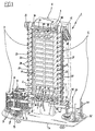
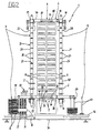
- the number 1 indicates in its entirety a machine for processing optical discs 2, according to the present invention.
- the machine 1 comprises a feeding station 3, a work station 4, an outlet station 5 storing the processed optical discs and transport means 6 to carry the optical discs 2 from the feeding station 3 to the work station 4 and, subsequently, from the work station 4 to the outlet station 5.
- the work station 4 comprises a plurality of work units 7 set parallel to each other and aligned vertically.
- each work unit 7 comprises at least a first processing device and at least a second processing device 8, 9.
- the first processing device comprises an optical recorder, set to record on virgin optical discs 2 the data read by an optical reader operatively connected with the work units 7 and not shown since it is known in the prior art.
- the second processing device comprises a serigrapher, set to effect personalisations or to print information on the recorded discs 2.
- the feeding station 3 comprises a feeding magazine 10 containing the optical discs 2 being processed.
- the feeding magazine 10 is constituted by a base feeding disc 11 bearing a series of loaders 12 distributed circumferentially around a vertical axis of rotation of the disc itself.
- the feeding magazine 10 further comprises a feeder device 13 having a first feeding motor 14 ( Figure 3) engaging rotationally a worm gear 15 to make a lifting carriage 16 translate thereon.
- the lifting carriage 16 presents a lifting arm 17 which acts under the discs 2 of the respective magazine 12 to support them and, when required, to lift them until taking to a pre-determined level the last disc 2 located at the top of the loader itself.
- the feeding station 3 further comprises a plurality of feeding supports 18 set parallel to each other and able to be aligned vertically each in correspondence with each work unit 7.
- the feeding supports 18 are distributed along a feeding conveyor 19 constituted by a feeding belt 20 maintained under tension by corresponding feeding pulleys 21 engaged on the base structure 1a of the machine 1.
- the feeding belt 21 is essentially placed in a position aside the work station 4 on the side of the recording devices 8.
- the feeding supports 18 are distanced from each other according to a measure corresponding to the distance between two consecutive work units 7 and each presents a grip pin 23, for the engagement of a respective optical disc 2.
- a feeder arm 24 Fastened to the base structure 1a of the machine 1 is present a feeder arm 24 which is movable between a first position, wherein the feeder arm 24 is located in proximity to the feeding magazine 10 to draw the disc 2 carried to the pre-set level by the lifting arm 17 and a second position, wherein said feeding arm 24 is located in proximity to the feeder conveyor 19 to deposit the disc itself on a respective feeding support 18.
- the withdrawal and deposit of the discs occurs for instance by means of suction cup elements or equivalent pneumatic means controlled vertically to approach or move away by the feeding arm or through the vertical motion thereof.
- the base feeder disc 9 rotates according to a pre-set angle around its own vertical axis, to replace the empty loader 12 with a full loader, thereby guaranteeing a continuous feeding of the machine 1.
- the outlet station in turn comprises a plurality of outlet supports 25 positioned parallel to each other and able each to be aligned vertically in correspondence with each work unit 7.
- the outlet supports 25 are distanced from each other according to a measure corresponding to the distance between two consecutive work units 7, and each presents an outlet pin 26, for the engagement of a respective optical disc 2.
- outlet supports 25 are borne by an outlet conveyor 27 which, by means of an outlet motor 28, translates the supports themselves cyclically and sequentially according to a stepped motion in correspondence with each work unit 7 and, subsequently, in correspondence with an outlet magazine 29 comprised in the outlet station 5.
- the outlet conveyor 27 is preferably constituted by an outlet belt 30 kept under tension by means of outlet pulleys 31 engaged on the base structure 1a of the machine 1.
- the outlet pulley 30 is essentially set in a position aside the work station 7 on the side of the serigraphy devices 9.
- the outlet magazine 29 comprises an outlet base disc 32 having a series of holders 33 arranged circumferentially around a vertical axis of rotation of the base disc itself.
- the outlet station 5 further comprises at least one outlet arm 34 movable between a first position wherein said outlet arm 34 is positioned in proximity to the outlet conveyor 27 to draw the processed optical discs 2 from the outlet supports 25 and a second position wherein the outlet arm 34 is positioned in proximity to the outlet magazine 29 to deposit said discs 2 in the holders 33.
- the discs 2 are drawn and deposited by means of suction cup elements or equivalent pneumatic means as for the feeding arm 24.
- the outlet arm 34 continues to deposit the discs 2 into the respective holder 33 until reaching a maximum collection limit, detected by suitable sensors. When this occurs the outlet base disc 32 rotates around its vertical axis setting an empty holder 33 to co-operate with the outlet arm 34.
- the transport means 6 comprise a plurality of transport arms 35 each of which, by means at least of one rigid support 36, is associated to one of the work units 7 to draw and deposit simultaneously the optical discs 2 being processed and/or already processed.
- each transport arm 35 runs in a groove 37 present on the respective rigid support 36 to transport the optical discs 2.
- each transport arm 35 is movable from a first position to a second position to bring a first grip head 39 respectively from the work station 4 to the feeding station 3.
- the first grip head 39 grasps the corresponding optical disc 2.
- the grip heads 39, 40 of the transport arm 35 can for instance present suction cup elements or pneumatic means functioning essentially like those present on the feeding arm 24 and outlet arm 34.
- the transport arm 35 moves again from the second position to the first position to transfer to the work station 4 the optical disc 2 drawn from the feeding support 18.
- each transport arm 35 is also associated at least a second grip head 40 movable between the work station 4 and the outlet station 5 following the translation of the transport arm itself between the first position and a third position.
- the transport arm 35 is set to carry the first grip head 39 between the feeding station 3 and the respective recording device 8 when the arm itself runs between the first position and the second position.
- the second grip head 40 is carried by the respective recording device 8 to the respective serigraphy device 9.
- the transport arm 35 moves between the first and the third position the first head 39 is carried by the respective recording device 8 to the respective serigraphy device 9. Simultaneously, the second grip head 40 is moved from the respective serigraphy device 9 to the outlet station 5.
- the transport of the optical discs 2 in the machine 1 occurs according to a method which shall be described better in the following exposition of the functional sequence of the various organs of the machine itself.
- the feeding magazine 10 is resupplied with loaders 12 carrying the respective discs 2 to be processed.
- the feeding arm 24 grasps a disc 2 from the respective loader 12 to carry it in correspondence with the feeding conveyor 19 and deposit it on the respective feeding support 18.
- the feeding belt 20 is made to move by one step by the second feeding motor 22.
- the feeding arm 18 moves to grasp an additional disc 2 from the feeding magazine 10, and subsequently to deposit it onto a new feeding support 18.
- the transfer operation of the optical discs 2 from the feeding magazine 10 to the feeding conveyor 19 is repeated until a pre-set number of feeding supports 18, for instance corresponding to the number of work units 7 present in the machine 1, are provided each with a respective optical disc 2 being processed, placed in correspondence with a respective work unit 7.
- the transport arms 35 simultaneously translate from the first position to the second position thereby taking the respective first grip heads 39 to draw the discs 2 from the feeding station 3.
- the feeding station 3 starts a new operating cycle whose purpose is to load a new series of discs 2.
- the discs 2 previously removed from the conveyor 19 are processed in the work station 4 to be subsequently removed therefrom, according to fourth phase of the subject method, and unloaded into the outlet station 5, according to a fifth phase of the method.
- each first grip head 39 grasps the recorded disc 2, whereupon each transport arm 35 translates between the first position and the third position.
- each first grip head 39 deposits the disc 2 into the serigraphy device 9. Whilst the discs 2 are being processed in the serigraphy devices 9 the transport arms 35 translate again from the third position to the second position grasping by means of the respective first grip heads 39, the new discs 2 set on the feeding conveyor 19. Each transport arm 35 then moves from the second position to the first position inserting the new disc 2 into the recording device 8.
- each transport arm 35 translates from the first position to the third position carrying the recorded disc 2 in correspondence with the serigraphy device 9 by means of the first grip head 39, and the serigraphed disc 2 in correspondence with the respective outlet support 25 by means of the second grip head 40.
- each transport arm 35 again reaches the second position to continue the cycle described above, simultaneously transferring a new disc 2 from the respective feeding support 20 to the recording device 8 by means of the first grip head 39, as well as the recorded disc 2, from the respective recording device 8, to the serigraphy device 9 by means of the second grip head 40.
- the outlet motor 28 moves step by step the outlet belt 30 comprised in the outlet conveyor 27 to make the discs 2 housed on the outlet supports 26 be drawn sequentially by the outlet arm 34.
- the outlet arm 34 transfers the disc directly into the outlet magazine depositing them in the respective holder 33.
- the operating cycle described above can be executed simultaneously on a maximum number of discs 2 corresponding to the number of work units 7 provided in the machine 1, in order to obtain a high productivity, particularly advantageous in large scale production.
- the machine 1 can be operatively set to perform different work cycles, both in regard to the content of the pieces recorded and of the serigraphy, and in regard to execution times.
- the first ten work units 7 can be used to record a given programme on the discs 2, whilst the remaining work units 7 record a different programme from the first.
- the machine 1 described above presents a compact structure and reduced size, and therefore is suited to be placed even in small spaces.
- the subject machine 1 also presents relatively reduced realisation and manufacturing costs, and it presents an exceptional operating flexibility which makes it suitable also for producing discs in small numbers.
- the invention solves all problems connected to the production of discs performed by means of manually executed loading and unloading phases, optimising production by means of the simultaneous transport of the discs being processed in the work station, operation which, even with the automation systems of the prior art, was performed individually on each disc thus resulting in very long production times.
- each transport arm 35 can be associated a third grip head, or in any case one grip head more than the number of processing devices pre-set in each work unit 7, to transfer the optical discs from the feeding station 3 to the outlet station 5 (through the various processing devices 7, 8) moving only the transport arm 35 between a first and a second operative position.
Landscapes
- Engineering & Computer Science (AREA)
- Manufacturing & Machinery (AREA)
- Manufacturing Optical Record Carriers (AREA)
- Processing And Handling Of Plastics And Other Materials For Molding In General (AREA)
Claims (17)
- Maschine zur Verarbeitung von optischen Platten, umfassend:dadurch gekennzeichnet, dass:mindestens eine Zuführstation (3);mindestens eine Bearbeitungsstation (4), umfassend eine Vielzahl von Bearbeitungseinheiten (7), die zueinander parallel angeordnet und vertikal ausgerichtet sind;mindestens eine Ausgangsstation (5), welche die optischen Platten (2) speichert;Transportmittel (6), um die optischen Platten (2) aus der Zuführstation (3) zur Bearbeitungsstation (4) und nachfolgend von der Bearbeitungsstation (4) zur Ausgangsstation (5) zu bringen;die Zuführstation (3) eine Vielzahl von Zuführstützen (18) umfasst, die zueinander parallel angeordnet und vertikal jeweils im Bereich einer jeden Bearbeitungseinheit (7) ausrichtbar sind;die Ausgangstation (5) umfasst eine Vielzahl von Ausgangsstützen (25), die zueinander parallel angeordnet und jeweils im Bereich einer jeden Bearbeitungseinheit (7) vertikal ausgerichtet sind;die Transportmittel (35) umfassen eine Vielzahl von Transportarmen (35), die jeweils einer Bearbeitungseinheit (7) zugeordnet sind, um gleichzeitig die optischen, zu bearbeitenden und/oder bearbeiteten Platten (2) zu entnehmen und abzulegen.
- Maschinen nach Anspruch 1, dadurch gekennzeichnet, dass jeder Transportarm (35) zwischen einer ersten Stellung und einer zweiten Stellung beweglich ist, um mindestens einen ersten Greifarm (39) aus der Bearbeitungsstation (4) zur Zuführstation zu bringen.
- Maschine nach Anspruch 2, dadurch gekennzeichnet, dass der Transportarm (35) in Längsrichtung zwischen der ersten Stellung und einer dritten Stellung beweglich ist, um den ersten Greifkopf (39) aus der Bearbeitungsstation (4) zur Ausgangsstation (5) zu bringen.
- Maschine nach Anspruch 2, dadurch gekennzeichnet, dass sie überdies mindestens einen zweiten Greifkopf (40) umfasst, der an jeden Transportarm (35) in Eingriff steht und zwischen der Bearbeitungsstation (4) und der Ausgangsstation (5) im Augenblick beweglich ist, bei dem der Transportarm selbst zwischen der ersten und der zweiten Stellung verstellt wird.
- Maschine nach Anspruch 1, dadurch gekennzeichnet, dass die Zuführstation (3) umfasst:mindestens einen Zuführspeicher (10), der die zu bearbeitenden, optischen Platten (2) enthält;mindestens einen Zuführförderer (19) der die Zuführstützen (18) trägt und schrittweise betätigbar ist, um taktweise und in Reihenfolge die Zuführstützen (18) in den Bereich des Zuführspeichers (10) und nachfolgend im Bereich der Bearbeitungseinheiten (7) zu bringen;mindestens einen Zuführarm (24), der zwischen einer ersten Stellung, in welcher der Zuführarm (24) in der Nähe des Zuführspeichers (10) gelegen ist, um die zu bearbeitenden Platten (2) aus demselben zu entnehmen, und einer zweiten Stellung beweglich, in der Transportarm in der Nähe des Zuführförderers (19) gelegen ist, um die Platten (2) abzulegen.
- Maschine nach Anspruch 5, dadurch gekennzeichnet, dass die Zuführstützen (18) von einander mit dem selben Abstand beabstandet sind, der zwischen zwei nacheinander folgenden Bearbeitungseinheiten (7) besteht.
- Maschine nach Anspruch 1, dadurch gekennzeichnet, dass die Ausgangsstation (5) umfasst:mindestens einen Ausgangsspeicher (29) der die optischen bearbeiteten Platten (2) enthält;mindestens einen Ausgangsförderer (27), der schrittweise betätigbar ist, um die Ausgangsstützen (28) taktweise und in Reihenfolge in den Bereich der Bearbeitungseinheiten (7) nachfolgend in den Bereich des Ausgangsspeichers (29) zu bringen;mindestens einen Ausgangsarm (34), der zwischen einer ersten Stellung, in der Ausgangsarm (34) in der Nähe des Ausgangförderers (27) liegt, um die bearbeiteten Platten (2) auf den Ausgangsstützen (25) zu entnehmen, und einer zweiten Stellung beweglich ist, in welcher der Transportarm in der Nähe des Ausgangmagazins (29) gelegen ist, um die Platten (2) abzulegen.
- Maschine nach Anspruch 7, dadurch gekennzeichnet, dass die Ausgangsstützen (25) von einander mit dem selben Abstand beabstandet sind, der zwischen zwei nacheinanderfolgenden Bearbeitungseinheiten (7) liegt.
- Maschine nach Anspruch 1, dadurch gekennzeichnet, dass jeder Transportarm (35) unabhängig voneinander den anderen Transportarmen (35) bewegbar ist, wobei der Maschine (1) ermöglicht wird, gleichzeitig Bearbeitungen mit verschiedenen Ausführungszeiten auszuführen.
- Maschine nach Anspruch 1, dadurch gekennzeichnet, dass die Bearbeitungseinheiten (7) mindestens eine erste und eine zweite Behandlungsvorrichtung (8, 9) umfassen, um mehrere Bearbeitungen an einer und derselben Platte zu vollziehen.
- Maschine nach Anspruch 10, dadurch gekennzeichnet, dass die erste und die zweite Behandlungsvorrichtung (8, 9) jeweils mindestens eine Datenaufzeichnungsvorrichtung (8) und mindestens eine Siebdruckvorrichtung (9) umfassen.
- Verfahren zum Transportieren von optischen Platten während deren Bearbeitung an einer Maschine, nach Anspruch 1, umfassend die folgenden Schritte:dadurch gekennzeichnet, dass:einen ersten Schritt, der die Ablage mindestens einer optischen Platte (2) in mindestens einer Zuführstation (3) vorsieht;einen zweiten Schritt zur Entnahme der optischen Platte (2) aus der Zuführstation (3);einen dritten Schritt zum Einbringen der optischen Platte (2) in mindestens eine Bearbeitungsstation (4);einen vierten Schritt zur Entfernung der optischen Platte (2) aus der Bearbeitungsstation (4) ;einen fünften Schritt, zum Entladen der optischen Platte (2) in mindestens eine Ausgangsstation (5);der erste Schritt vorsieht, eine Vielzahl von optischen Platten (2) in vertikaler Ausrichtung an entsprechenden, der Zuführstation (3) angehörenden Zuführstützen (8) anzuordnen, wobei jede optische Platte (2) im Bereich einer entsprechenden Bearbeitungsstation (4) angesetzt ist;der fünfte Schritt sieht vor, eine Vielzahl von optischen Platten (2) in vertikaler Ausrichtung an der Ausgangsstation (5) angehörenden entsprechenden Ausgangsstütze (25) anzuordnen, wobei jede Ausgangsstütze (25) im Bereich einer entsprechenden Bearbeitungsstation (7) angesetzt ist.
- Verfahren nach Anspruch 12, dadurch gekennzeichnet, dass:der zweite Schritt sieht vor, simultan die optischen, zu bearbeitenden Platten (2) zu entnehmen, die an entsprechenden Zuführstützen (18) aufgenommen sind;der dritte Schritt sieht vor, gleichzeitig die zu bearbeitenden, optischen Platten (2) in die Bearbeitungseinheit (7) einzubringen;der vierte Schritt sieht vor, simultan die optischen, von den Bearbeitungseinheiten (7) bearbeiteten Platten (2) zu entfernen;der fünfte Schritt sieht vor, gleichzeitig die optischen Platten (2) an entsprechenden Ausgangsstützen (25) zu entladen.
- Verfahren nach Anspruch 12, dadurch gekennzeichnet, dass der zweite und der dritte Schritt an den zu bearbeitenden Platten (2) gleichzeitig mit der Durchführung des vierten und des fünften Schrittes an den bearbeiteten Platten (2) ausgeführt werden.
- Verfahren nach Anspruch 12, gekennzeichnet durch den Schritt, die optischen, zu bearbeitenden Platten (2) unabhängig voneinander von den Zuführstützen (18) zu den Bearbeitungseinheiten (7)d un nachfolgend zu den Ausgangsstützen (25) zu bringen.
- Verfahren nach Anspruch 12, dadurch gekennzeichnet, dass der erste Schritt die folgenden Nebenschritte umfasst:Bereitstellung der Zuführstützen (18) in gegenseitiger Ausrichtung ;schrittweise und simultane Bewegung der Zuführstützen (18), wobei diese letzteren in Reihenfolge und taktweise in den bereich mindestens eines Zuführspeichers (10) gebracht werden;Überführung der Platten (2) einzeln aus den Zuführspeicher (10) zu den entsprechenden Zuführstützen (18) in Gleichlauf mit der Bewegung der Zuführstützen (25).
- Verfahren nach Anspruch 12, dadurch gekennzeichnet, dass nach dem fünften Schritt die folgenden Nebenschritte durchgeführt werden;schrittweises Bewegen der Ausgangsstützen (25) in Reihenfolge und taktweise in den Bereich mindestens eines Ausgangsspeichers (29);einzelnes Überführen der Platten (2) von den Ausgangsstützen (25) zum Ausgangsspeicher (29) im Gleichlauf mit der Bewegung der Ausgangsstützen selbst.
Priority Applications (4)
| Application Number | Priority Date | Filing Date | Title |
|---|---|---|---|
| DE69708108T DE69708108T2 (de) | 1997-11-21 | 1997-11-21 | Maschine zur Verarbeitung von optischen Platten und Verfahren zum Transportieren von optischen Platten während deren Verarbeitung |
| EP97830614A EP0918324B1 (de) | 1997-11-21 | 1997-11-21 | Maschine zur Verarbeitung von optischen Platten und Verfahren zum Transportieren von optischen Platten während deren Verarbeitung |
| AT97830614T ATE208531T1 (de) | 1997-11-21 | 1997-11-21 | Maschine zur verarbeitung von optischen platten und verfahren zum transportieren von optischen platten während deren verarbeitung |
| CA002242386A CA2242386A1 (en) | 1997-11-21 | 1998-07-06 | An apparatus for processing optical discs and method for transporting optical discs being processed thereby |
Applications Claiming Priority (1)
| Application Number | Priority Date | Filing Date | Title |
|---|---|---|---|
| EP97830614A EP0918324B1 (de) | 1997-11-21 | 1997-11-21 | Maschine zur Verarbeitung von optischen Platten und Verfahren zum Transportieren von optischen Platten während deren Verarbeitung |
Publications (2)
| Publication Number | Publication Date |
|---|---|
| EP0918324A1 EP0918324A1 (de) | 1999-05-26 |
| EP0918324B1 true EP0918324B1 (de) | 2001-11-07 |
Family
ID=8230865
Family Applications (1)
| Application Number | Title | Priority Date | Filing Date |
|---|---|---|---|
| EP97830614A Expired - Lifetime EP0918324B1 (de) | 1997-11-21 | 1997-11-21 | Maschine zur Verarbeitung von optischen Platten und Verfahren zum Transportieren von optischen Platten während deren Verarbeitung |
Country Status (4)
| Country | Link |
|---|---|
| EP (1) | EP0918324B1 (de) |
| AT (1) | ATE208531T1 (de) |
| CA (1) | CA2242386A1 (de) |
| DE (1) | DE69708108T2 (de) |
Families Citing this family (5)
| Publication number | Priority date | Publication date | Assignee | Title |
|---|---|---|---|---|
| IT1312476B1 (it) * | 1999-05-11 | 2002-04-17 | Bernardini Srl | Stazioni di carico e scarico per apparecchiatura di registrazione didischi ottici e simili |
| US6301217B1 (en) | 1998-06-18 | 2001-10-09 | Bernardini S.R.L. | Apparatus for recording optical disks featuring increased operating speed |
| DE20003125U1 (de) * | 2000-02-21 | 2001-06-28 | Hellmuth, André, 55129 Mainz | Datenträger-Vervielfältigungsvorrichtung |
| DE10231767C1 (de) * | 2002-07-13 | 2003-08-14 | Krauss Maffei Kunststofftech | Multiformat-Spindeltransportvorrichtung für Transport und Kühlung von flachen Substraten |
| CN101159150B (zh) | 2006-10-03 | 2010-06-02 | 精工爱普生株式会社 | 介质处理装置以及介质处理装置的控制方法 |
Family Cites Families (2)
| Publication number | Priority date | Publication date | Assignee | Title |
|---|---|---|---|---|
| JP2559617B2 (ja) * | 1988-03-24 | 1996-12-04 | キヤノン株式会社 | 基板処理装置 |
| US5734629A (en) * | 1995-12-28 | 1998-03-31 | Rimage Corporation | CD transporter |
-
1997
- 1997-11-21 EP EP97830614A patent/EP0918324B1/de not_active Expired - Lifetime
- 1997-11-21 DE DE69708108T patent/DE69708108T2/de not_active Expired - Lifetime
- 1997-11-21 AT AT97830614T patent/ATE208531T1/de not_active IP Right Cessation
-
1998
- 1998-07-06 CA CA002242386A patent/CA2242386A1/en not_active Abandoned
Also Published As
| Publication number | Publication date |
|---|---|
| ATE208531T1 (de) | 2001-11-15 |
| EP0918324A1 (de) | 1999-05-26 |
| DE69708108T2 (de) | 2002-03-14 |
| DE69708108D1 (de) | 2001-12-13 |
| CA2242386A1 (en) | 1999-05-21 |
Similar Documents
| Publication | Publication Date | Title |
|---|---|---|
| CN108545278B (zh) | 固态硬盘高速自动贴标生产线 | |
| CA1307209C (en) | Article handling apparatus for storage and delivery of plural types of articles | |
| JP5295361B2 (ja) | 記憶装置試験システムへの記憶装置のバルク供給 | |
| JPH03177206A (ja) | 物品の取り出し・格納方法と装置 | |
| US5808828A (en) | Installation intended for automatic recording and/or readout onto or from information carriers | |
| CN1043031A (zh) | 盘存储装置 | |
| JP3844546B2 (ja) | 包装用製品の整理統合のための自動化装置及び方法 | |
| EP0918324B1 (de) | Maschine zur Verarbeitung von optischen Platten und Verfahren zum Transportieren von optischen Platten während deren Verarbeitung | |
| KR20220051016A (ko) | 처리 유닛에 제품의 그룹을 공급하는 방법 및 시스템 | |
| CN110665827B (zh) | 壳状牙科器械的分拣系统 | |
| US5983601A (en) | Machine for the automated packaging of needles and attached sutures | |
| US5549434A (en) | Cassette feed system and method | |
| JP2001526617A (ja) | 高速自動装置及びラック制御ユニットを有する委託集配設備 | |
| US6585100B2 (en) | Arrangement for feeding and/or taking away magazines filled with articles | |
| CN113155035A (zh) | 用于cnc产品的外观检测装置 | |
| US20100290868A1 (en) | System for handling slides | |
| US6205748B1 (en) | Suture package unloading arrangement in a machine for the automated packaging of needles and attached sutures | |
| CN208498997U (zh) | 固态硬盘高速自动贴标生产线 | |
| CN215373853U (zh) | 用于cnc产品的外观检测装置 | |
| CN214729936U (zh) | 电子元器件的包装机 | |
| JP3685344B2 (ja) | ディスクカートリッジの箱詰め方法およびその装置 | |
| WO1994019166A2 (en) | Changing device for manufacturiing information carriers by injection moulding | |
| JP3730701B2 (ja) | 情報記録媒体自動マウント装置及び情報記録媒体自動マウント方法 | |
| JPH07115094B2 (ja) | 板材加工法 | |
| CN115401850B (zh) | 一种自动镭雕热熔装置 |
Legal Events
| Date | Code | Title | Description |
|---|---|---|---|
| PUAI | Public reference made under article 153(3) epc to a published international application that has entered the european phase |
Free format text: ORIGINAL CODE: 0009012 |
|
| 17P | Request for examination filed |
Effective date: 19980526 |
|
| AK | Designated contracting states |
Kind code of ref document: A1 Designated state(s): AT BE DE DK ES FR GB IE IT NL |
|
| AX | Request for extension of the european patent |
Free format text: AL;LT;LV;MK;RO;SI |
|
| AKX | Designation fees paid |
Free format text: AT BE DE DK ES FR GB IE IT NL |
|
| 17Q | First examination report despatched |
Effective date: 20001228 |
|
| GRAG | Despatch of communication of intention to grant |
Free format text: ORIGINAL CODE: EPIDOS AGRA |
|
| GRAG | Despatch of communication of intention to grant |
Free format text: ORIGINAL CODE: EPIDOS AGRA |
|
| GRAH | Despatch of communication of intention to grant a patent |
Free format text: ORIGINAL CODE: EPIDOS IGRA |
|
| GRAH | Despatch of communication of intention to grant a patent |
Free format text: ORIGINAL CODE: EPIDOS IGRA |
|
| GRAA | (expected) grant |
Free format text: ORIGINAL CODE: 0009210 |
|
| AK | Designated contracting states |
Kind code of ref document: B1 Designated state(s): AT BE DE DK ES FR GB IE IT NL |
|
| PG25 | Lapsed in a contracting state [announced via postgrant information from national office to epo] |
Ref country code: NL Free format text: LAPSE BECAUSE OF FAILURE TO SUBMIT A TRANSLATION OF THE DESCRIPTION OR TO PAY THE FEE WITHIN THE PRESCRIBED TIME-LIMIT Effective date: 20011107 Ref country code: BE Free format text: LAPSE BECAUSE OF FAILURE TO SUBMIT A TRANSLATION OF THE DESCRIPTION OR TO PAY THE FEE WITHIN THE PRESCRIBED TIME-LIMIT Effective date: 20011107 Ref country code: AT Free format text: LAPSE BECAUSE OF FAILURE TO SUBMIT A TRANSLATION OF THE DESCRIPTION OR TO PAY THE FEE WITHIN THE PRESCRIBED TIME-LIMIT Effective date: 20011107 |
|
| REF | Corresponds to: |
Ref document number: 208531 Country of ref document: AT Date of ref document: 20011115 Kind code of ref document: T |
|
| PG25 | Lapsed in a contracting state [announced via postgrant information from national office to epo] |
Ref country code: IE Free format text: LAPSE BECAUSE OF FAILURE TO SUBMIT A TRANSLATION OF THE DESCRIPTION OR TO PAY THE FEE WITHIN THE PRESCRIBED TIME-LIMIT Effective date: 20011121 |
|
| REG | Reference to a national code |
Ref country code: IE Ref legal event code: FG4D |
|
| REF | Corresponds to: |
Ref document number: 69708108 Country of ref document: DE Date of ref document: 20011213 |
|
| REG | Reference to a national code |
Ref country code: GB Ref legal event code: IF02 |
|
| ET | Fr: translation filed | ||
| PG25 | Lapsed in a contracting state [announced via postgrant information from national office to epo] |
Ref country code: DK Free format text: LAPSE BECAUSE OF FAILURE TO SUBMIT A TRANSLATION OF THE DESCRIPTION OR TO PAY THE FEE WITHIN THE PRESCRIBED TIME-LIMIT Effective date: 20020207 |
|
| NLV1 | Nl: lapsed or annulled due to failure to fulfill the requirements of art. 29p and 29m of the patents act | ||
| PG25 | Lapsed in a contracting state [announced via postgrant information from national office to epo] |
Ref country code: ES Free format text: LAPSE BECAUSE OF FAILURE TO SUBMIT A TRANSLATION OF THE DESCRIPTION OR TO PAY THE FEE WITHIN THE PRESCRIBED TIME-LIMIT Effective date: 20020530 |
|
| REG | Reference to a national code |
Ref country code: IE Ref legal event code: MM4A |
|
| PLBE | No opposition filed within time limit |
Free format text: ORIGINAL CODE: 0009261 |
|
| STAA | Information on the status of an ep patent application or granted ep patent |
Free format text: STATUS: NO OPPOSITION FILED WITHIN TIME LIMIT |
|
| 26N | No opposition filed | ||
| PGFP | Annual fee paid to national office [announced via postgrant information from national office to epo] |
Ref country code: FR Payment date: 20021108 Year of fee payment: 6 |
|
| PGFP | Annual fee paid to national office [announced via postgrant information from national office to epo] |
Ref country code: GB Payment date: 20021120 Year of fee payment: 6 |
|
| PG25 | Lapsed in a contracting state [announced via postgrant information from national office to epo] |
Ref country code: GB Free format text: LAPSE BECAUSE OF NON-PAYMENT OF DUE FEES Effective date: 20031121 |
|
| GBPC | Gb: european patent ceased through non-payment of renewal fee |
Effective date: 20031121 |
|
| PG25 | Lapsed in a contracting state [announced via postgrant information from national office to epo] |
Ref country code: FR Free format text: LAPSE BECAUSE OF NON-PAYMENT OF DUE FEES Effective date: 20040730 |
|
| REG | Reference to a national code |
Ref country code: FR Ref legal event code: ST |
|
| PG25 | Lapsed in a contracting state [announced via postgrant information from national office to epo] |
Ref country code: IT Free format text: LAPSE BECAUSE OF NON-PAYMENT OF DUE FEES Effective date: 20051121 |
|
| PGFP | Annual fee paid to national office [announced via postgrant information from national office to epo] |
Ref country code: DE Payment date: 20091119 Year of fee payment: 13 |
|
| REG | Reference to a national code |
Ref country code: DE Ref legal event code: R119 Ref document number: 69708108 Country of ref document: DE Effective date: 20110601 Ref country code: DE Ref legal event code: R119 Ref document number: 69708108 Country of ref document: DE Effective date: 20110531 |
|
| PG25 | Lapsed in a contracting state [announced via postgrant information from national office to epo] |
Ref country code: DE Free format text: LAPSE BECAUSE OF NON-PAYMENT OF DUE FEES Effective date: 20110531 |