EP0922562A1 - Motor torque control method for press machine and press machine - Google Patents
Motor torque control method for press machine and press machine Download PDFInfo
- Publication number
- EP0922562A1 EP0922562A1 EP98905835A EP98905835A EP0922562A1 EP 0922562 A1 EP0922562 A1 EP 0922562A1 EP 98905835 A EP98905835 A EP 98905835A EP 98905835 A EP98905835 A EP 98905835A EP 0922562 A1 EP0922562 A1 EP 0922562A1
- Authority
- EP
- European Patent Office
- Prior art keywords
- torque
- motor
- acceleration
- velocity
- torque limit
- Prior art date
- Legal status (The legal status is an assumption and is not a legal conclusion. Google has not performed a legal analysis and makes no representation as to the accuracy of the status listed.)
- Granted
Links
- 238000000034 method Methods 0.000 title claims description 15
- 230000001133 acceleration Effects 0.000 claims abstract description 76
- 230000003068 static effect Effects 0.000 claims description 12
- 238000010586 diagram Methods 0.000 description 8
- 239000002184 metal Substances 0.000 description 4
- 229910052751 metal Inorganic materials 0.000 description 4
- 230000015654 memory Effects 0.000 description 3
- 230000000694 effects Effects 0.000 description 2
- 230000010354 integration Effects 0.000 description 2
Images



Classifications
-
- B—PERFORMING OPERATIONS; TRANSPORTING
- B30—PRESSES
- B30B—PRESSES IN GENERAL
- B30B15/00—Details of, or accessories for, presses; Auxiliary measures in connection with pressing
- B30B15/14—Control arrangements for mechanically-driven presses
Definitions
- the present invention relates to a pressing machine for conducting pressing by means of motor output torque and to a torque control method for a motor controlling this press.
- Pressing machines for conducting pressing by controlling pressing force by controlling the output torque of a motor are commonly known.
- This conventional pressing force control obtains the required pressing force by applying a torque limit to the output torque of a motor, in other words, by restricting the output torque of the motor.
- the torque limit value for the motor is derived from the intended pressing force and the static relationship between the torque generated by the motor and the pressing force.
- the static relationship between the torque T generated by the motor and the pressing force fp is given by Equation (1) below.
- fp a ⁇ T
- a is a coefficient for converting rotational force to linear force.
- a torque limit value Tm corresponding to the target pressing force F is derived from equation (2) above, and the required pressing force is obtained by driving the motor whilst restricting its output torque to this derived torque limit value Tm.
- Fig. 9 is a control block diagram of a servo motor of a conventional pressing machine for conducting pressing by restricting the output torque of the servo motor where a servo motor is used as a motor.
- Velocity control means 1 implements velocity loop control, such as proportional plus integral control, or the like, in accordance with the instructed velocity command Vc and a velocity feedback value vf which is fed back from a position and velocity detector 6 for detecting the rotational position and velocity of a servo motor 5, and determines a torque command Tc.
- the present invention is a motor torque control method for a pressing machine which applies pressing force by limiting the output torque of a motor by restricting a torque command through torque limiting means provided in a motor control circuit, wherein a torque limit value corresponding to a target pressing force is corrected by the torque required for acceleration or deceleration, and the motor is driven whilst the torque command value is restricted by this corrected torque limit value, such that the target pressing force is applied to a work during acceleration or deceleration.
- the torque required for acceleration or deceleration is determined by the actual velocity detected by a velocity detector or the acceleration as calculated from the velocity command, and this is taken as a torque limit correction value.
- an observer for estimating acceleration from the torque command value and the actual velocity detected by a velocity detector is provided, and the acceleration estimated by the observer is taken as the aforementioned necessary torque for acceleration or deceleration, and this is taken as the torque limit correction value.
- the present invention corrects the torque limit value corresponding to the target pressing force by the torque required for acceleration or deceleration and takes this as a torque limit value for restricting the torque command, it is possible to apply the target pressing force to a work at all times, during acceleration and deceleration also. Consequently, instances of the metal pattern rupturing due to application of excessive pressing force to the work, or of insufficient pressing force, do not occur.
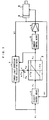
- the motor control method illustrated in Fig. 1 is characterized in that torque limit correction value calculating means 7 described hereinafter is appended to the conventional motor control method illustrated in Fig. 9.
- fp a (Tm + ⁇ Tm) - M ⁇
- Tm is a static torque limit value corresponding to the target pressing force F
- Tm F/a .
- a which converts rotational force to linear force.
- Equation (6'') above the value of M is already known, since it is the total mass of the moving body, and the value of a is also an already known constant which may be derived by experimentation, or the like, since it is a coefficient for converting rotational force to linear force. Therefore, if the acceleration ⁇ of the motor is detected, it is possible to determine the torque limit correction value ⁇ Tm from equation (6'') above.
- the acceleration ⁇ can be determined by differentiating the velocity command Vc with respect to time. Alternatively, it may be determined by differentiating the velocity feedback value Vf fed back by the position and velocity detector 6, with respect to time. Moreover, by using an observer, it may be estimated from the torque command Tc' output by torque limiting means 2 (in other words, the torque command transferred to current control means 3 of the current loop) and the velocity feedback value Vf.
- Fig. 1 shows a case where torque limit correction value calculating means 7 receives three inputs, namely, a velocity command Vc, velocity feedback value Vf, and torque command value Tc' which is output by torque limiting means 2.
- torque limit correction value calculating means 7 receives three inputs, namely, a velocity command Vc, velocity feedback value Vf, and torque command value Tc' which is output by torque limiting means 2.
- Fig. 1 should be interpreted as showing that torque limit correction value calculating means 7 inputs either velocity command Vc, velocity feedback value Vf, or torque command Tc' plus velocity feedback value Vf.
- the torque limit correction value ⁇ Tm is determined from the velocity feedback value Vf.
- the torque limit correction value ⁇ Tm is determined from the command velocity Vc.
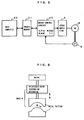
- the motor torque acceleration ⁇ t is determined by multiplying the torque command Tc' by a/M at a multiplier 12. Moreover, the difference (Vf - A1) between the velocity feedback value Vf and the estimated acceleration (output of integrator 13 : A1) is given integral plus proportional processing in section 14 to derive an estimated disturbance acceleration X. This processing is description below.
- the estimated acceleration ⁇ is found by adding this estimated disturbance acceleration X to the motor torque acceleration ⁇ t.
- the torque limit correction value ⁇ Tm is determined by multiplying the estimated acceleration ⁇ by M/a at a multiplier 15.
- the aforementioned estimated velocity (A1) is obtained by integration of the estimated acceleration ⁇ by integrator 13.
- reference numeral 20 denotes a host computer, such as an NC controller, or the like, which outputs movement commands, etc. on the basis of an operating program via a shared memory 21 to a motor control circuit 22, which is a digital servo circuit for controlling a servo motor.
- this motor control circuit 22 comprises a processor, memories, such as a ROM and a RAM, and an interface for inputting feedback values of position and velocity, fed back from position and velocity detector 6, and feedback values for the motor drive current, via servo amplifier 4, and the like, and it implements loop control of position, velocity and current, thereby driving and controlling a servo motor 5 via an amplifier 4.
- the position and velocity detector 6 is installed on the rotor shaft of the servo motor 5 and detects the rotational position and velocity of the servo motor, which it feeds back to the motor control circuit 22.
- the composition and operation of this control section is commonly known in the prior art, but the present invention is characterized in that, in the loop control of position, velocity and current by the aforementioned motor control circuit 22, a torque limit value is calculated for applying a torque limit to the torque command output by the velocity loop control, and the torque command is restricted by this derived torque limit value and output to the current loop.
- torque limit processing is conducted by determining a torque limit correction value ⁇ Tm according to the velocity feedback value, Vf, using the torque limit calculating means shown in Fig. 2, and a torque command Tc' for supply to the current loop is determined thereby.
- the coefficient M/a in the multiplier 11 in Fig. 2 for determining the torque limit correction value from the acceleration is derived and set from the total mass of the moving body M and the aforementioned coefficient, a.
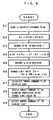
- the velocity feedback value Vf(n) for the cycle in question is read in (step S1), and, from this velocity feedback value Vf(n), the velocity feedback value Vf(n-1) for the previous cycle, which is recorded in a register, is subtracted from this velocity feedback value Vf(n) to derive a velocity differential ⁇ v (step S2). Moreover, the velocity feedback value Vf(n) for the current cycle read in at step S1 is stored in a register 1 to be used as the previous cycle velocity feedback value Vf(n-1) in the subsequent cycle (step S3).
- the acceleration ⁇ (n) for the current cycle is derived from the velocity differential, ⁇ v, determined at step S2 and the previous cycle acceleration ⁇ (n-1) stored in register 2 (step S4).
- ⁇ (n) k ⁇ v + (1-k) ⁇ (n-1)
- the acceleration ⁇ (n) determined in this way is stored in register 2 to be used as the previous cycle acceleration ⁇ (n-1) in the subsequent cycle (step S5).
- M/a is set previously in the motor control circuit 22.
- the torque limit value Tm' is determined by adding the torque limit correction value ⁇ Tm to the previously derived static torque limit value Tm.
- a torque command Tc is determined by carrying out conventional velocity loop processing using the velocity command Vc derived by positional loop processing and the velocity feedback value Vf (step S7).
- the torque command Tc determined here is compared with the torque limit value Tm' determined at step S6, and if the torque command Tc is the smaller, the torque command Tc is delivered directly to the current loop as the torque command Tc' for the current loop. Furthermore, if the torque command Tc is larger than the torque limit value Tm', then this torque limit value Tm' becomes the torque command Tc' for the current loop, and the torque command restricted to this torque limit value Tm' is delivered to the current loop, whereupon the processing of the velocity loop ends (steps S8, S9).
- the acceleration ⁇ is determined from the velocity feedback value Vf
- the force required for acceleration or deceleration is determined from this acceleration ⁇ , and the torque limit value is corrected by removing the effects of this force such that the set target pressing force F is obtained at all times, then even if the metal pattern is placed against a work and pressing is carried out during acceleration or deceleration, it is possible to press the work with the set target pressing force F.
- the acceleration ⁇ is determined from the velocity feedback value Vf
- the torque limit correction value ⁇ Tm is determined from this derived acceleration ⁇
- the acceleration ⁇ is determined from the velocity command Vc instead of the velocity feedback value Vf
- the processing implemented by the processor in the motor control circuit 22 using the torque limit correction value calculating means shown in Fig. 3 simply involves reading out the command velocity Vc(n) instead of Vf(n) at step S1 in Fig. 6, whereupon Vf(n) is replaced by Vc(n) in steps S1 - S3, so the processing is virtually the same as that in Fig. 6. Therefore, further description of the processing involved in Fig. 3 is omitted here.
- This processing is carried out for each processing cycle of the velocity loop.
- step T2 After reading the acceleration feedback value Vf (step T1), the torque command value Tc' for the previous cycle (that is, torque command value instructed to current loop after implementation of torque limiting), which is stored in register 1, and the estimated disturbance acceleration X are read, and an estimated acceleration ⁇ is determined by adding the estimated disturbance acceleration X to the product of torque command value Tc' and a/M (step T2).
- the estimated velocity (A1) is determined by multiplying the estimated acceleration ⁇ by the value of the accumulator A1.
- the processing of integrator 13 in Fig. 4 is implemented (step T3).
- a velocity differential ⁇ v is determined by subtracting the estimated velocity (A1), which is the value of the aforementioned accumulator A1, from the velocity feedback value Vf read at step T1, and this velocity differential ⁇ v is added to the accumulator A2 (step T4).
- the processing in step T5 is equivalent to the processing of proportional plus integral processing means 14 in Fig. 4.
- a torque command Tc is determined by velocity loop processing, similarly to the prior art, in accordance with the velocity command Vc determined by positional loop processing and the velocity feedback value Vf (step T7).
- the torque command Tc is compared with the torque limit value Tm' derived at step T6, and if the torque command Tc is smaller, it is taken directly as the torque command Tc' for the current loop, whereas if the torque command Tc is the larger, then the torque limit value Tm' is stored as the torque command Tc' in a register, and it is also delivered to the current loop processing (steps T8 - T10). Thereafter, the above processing is repeated for each velocity loop processing cycle.
- the torque command is corrected by a value corresponding to the torque required for acceleration or deceleration, and control is implemented such that the target pressing force is obtained.
Landscapes
- Engineering & Computer Science (AREA)
- Mechanical Engineering (AREA)
- Control Of Presses (AREA)
- Control Of Electric Motors In General (AREA)
Abstract
Description
Claims (7)
- A motor torque control method for a pressing machine for applying a prescribed pressing force by restricting the output torque of a motor, comprising steps of:correcting a torque limit value corresponding to a target pressing force by the torque value required for acceleration or deceleration of the motor; andrestricting the torque command value to said motor by said corrected torque limit value, and applying the aforementioned target pressing force to a work while accelerating or decelerating said motor.
- The motor torque control method for a pressing machine according to claim 1, wherein the torque value required for acceleration or deceleration of said motor is determined from an acceleration as calculated from the actual velocity detected by a velocity detector.
- The motor torque control method for a pressing machine according to claim 1, wherein the torque value required for acceleration or deceleration of said motor is determined from an acceleration as calculated from a velocity command.
- The motor torque control method for a pressing machine according to claim 1, wherein the torque value required for acceleration or deceleration of said motor is determined from an estimated acceleration output by an observer, and furthermore, said observer inputs the actual velocity detected by a velocity detector and a torque command delivered to the current loop, and outputs an estimated acceleration.
- A pressing machine for applying pressing force, comprising:torque limiting means for restricting torque commands in a motor control circuit, whereby the output torque of a motor is restricted by restricting torque commands through said torque limiting means; andtorque limit correction value calculating means for determining an acceleration from a command velocity or a detected velocity from a velocity detector for detecting the velocity of the motor, and calculating a torque limit correction value from said acceleration;
wherein the torque limit value of said torque limiting means is derived by adding the torque limit correction value determined by said torque limit correction value calculating means to a torque limit value corresponding to the target pressing force. - A pressing machine for applying pressing force, comprising:torque limiting means for restricting torque commands in a motor control circuit, in which the output torque of a motor is restricted by restricting torque commands through said torque limiting means;an observer for estimating and outputting acceleration values, wherein said observer inputs the actual velocity as detected by a velocity detector and a torque command delivered to the current loop, and outputs a estimated acceleration; andmeans for calculating a torque value required for acceleration or deceleration from the estimated acceleration output by said observer, and outputting this calculated torque value to said torque limiting means;
wherein the torque limit value of said torque limiting means is derived by adding the torque value required for acceleration or deceleration as calculated from the output of said observer to a torque limit value corresponding to the target pressing force. - A motor control circuit for implementing loop control of position, velocity and current, which inputs movement commands based on an operating program, and feedback signals from a position and velocity detector installed on the rotor shaft of a motor, comprising:torque limiting means for applying a torque limit to a torque command generated by velocity loop control, the torque required to cause a prescribed force to act on a machine driven by a motor operated at constant speed being previously set as a static torque limit value in said torque limiting means; andtorque limit correction value calculating means for correcting the torque limit value of said torque limiting means, such that said prescribed force acts on said machine, even when the motor is operates at a certain acceleration, the torque limit value of said torque limiting means being corrected by detecting the acceleration of a motor, determining a torque limit correction value from this detected acceleration, and adding this torque limit correction value to said static torque limit value.
Applications Claiming Priority (3)
| Application Number | Priority Date | Filing Date | Title |
|---|---|---|---|
| JP07090297A JP3694573B2 (en) | 1997-03-10 | 1997-03-10 | Motor torque control method in press machine and press machine |
| JP7090297 | 1997-03-10 | ||
| PCT/JP1998/000982 WO1998040203A1 (en) | 1997-03-10 | 1998-03-10 | Motor torque control method for press machine and press machine |
Publications (3)
| Publication Number | Publication Date |
|---|---|
| EP0922562A1 true EP0922562A1 (en) | 1999-06-16 |
| EP0922562A4 EP0922562A4 (en) | 2002-02-27 |
| EP0922562B1 EP0922562B1 (en) | 2008-11-19 |
Family
ID=13444935
Family Applications (1)
| Application Number | Title | Priority Date | Filing Date |
|---|---|---|---|
| EP98905835A Expired - Lifetime EP0922562B1 (en) | 1997-03-10 | 1998-03-10 | Motor torque control method for press machine and press machine |
Country Status (5)
| Country | Link |
|---|---|
| US (1) | US6211636B1 (en) |
| EP (1) | EP0922562B1 (en) |
| JP (1) | JP3694573B2 (en) |
| DE (1) | DE69840225D1 (en) |
| WO (1) | WO1998040203A1 (en) |
Cited By (6)
| Publication number | Priority date | Publication date | Assignee | Title |
|---|---|---|---|---|
| WO2005016636A1 (en) * | 2003-07-17 | 2005-02-24 | Gebr. Schmidt Fabrik für Feinmechanik GmbH & Co. KG | Electric press |
| WO2007022755A3 (en) * | 2005-08-24 | 2007-05-10 | Mueller Weingarten Maschf | Method and device for controlling and adjusting forces on servo-electric presses |
| EP1898284A3 (en) * | 2006-09-05 | 2014-03-12 | Fanuc Corporation | Control device for servo die cushion |
| EP1892081B1 (en) * | 2001-12-21 | 2014-06-25 | Aida Engineering, Ltd. | Press machine |
| WO2014191285A1 (en) * | 2013-05-28 | 2014-12-04 | Schuler Pressen Gmbh | Method for controlling a press with a variable gear ratio |
| DE102011115932B4 (en) | 2010-11-09 | 2018-03-22 | Aida Engineering, Ltd. | Control device for a servo-press and method for controlling a servo-press |
Families Citing this family (15)
| Publication number | Priority date | Publication date | Assignee | Title |
|---|---|---|---|---|
| SG84531A1 (en) * | 1999-05-20 | 2001-11-20 | Univ Singapore | Disturbance attenuation in a precision servomechanism by a frequency-separated acceleration soft sensor |
| US6300735B1 (en) * | 2000-03-22 | 2001-10-09 | Caterpillar Inc. | Control for a two degree of freedom electromechanical transmission and associated method |
| JP4568408B2 (en) * | 2000-06-26 | 2010-10-27 | 株式会社アマダ | Ram control method and apparatus for press brake |
| US7015670B2 (en) * | 2004-05-14 | 2006-03-21 | Moog Inc. | Method of controlling a high-friction electro-mechanical servo-mechanism to minimize the power needed to hold a loaded output member |
| JP4874590B2 (en) * | 2005-07-08 | 2012-02-15 | ファナック株式会社 | Control device and control method for die cushion mechanism |
| US8972032B2 (en) * | 2009-06-25 | 2015-03-03 | GM Global Technology Operations LLC | Method for overload protection of SMA device |
| JP2011062725A (en) * | 2009-09-17 | 2011-03-31 | Aida Engineering Ltd | Press machine and method of controlling the same |
| JP5193333B2 (en) * | 2011-05-18 | 2013-05-08 | 株式会社小松製作所 | Electric motor control device and control method thereof |
| CN105027013B (en) * | 2013-03-07 | 2017-09-19 | 株式会社牧野铣床制作所 | Machine tool feed axis control method and feed axis control device |
| KR20140126851A (en) * | 2013-04-23 | 2014-11-03 | 서울대학교산학협력단 | Non-tuning non-linear control method for servo controller having current limiting device |
| WO2015009850A1 (en) | 2013-07-19 | 2015-01-22 | Pro-Dex, Inc. | Torque-limiting screwdrivers |
| JP6212069B2 (en) | 2015-05-12 | 2017-10-11 | ファナック株式会社 | Injection molding machine that drives and controls moving parts with a motor |
| US10383674B2 (en) | 2016-06-07 | 2019-08-20 | Pro-Dex, Inc. | Torque-limiting screwdriver devices, systems, and methods |
| JP6426691B2 (en) * | 2016-12-22 | 2018-11-21 | ファナック株式会社 | Numerical control device |
| KR102762259B1 (en) | 2018-08-20 | 2025-02-03 | 프로-덱스, 인코포레이티드. | Torque-limiting devices, systems, and methods |
Family Cites Families (8)
| Publication number | Priority date | Publication date | Assignee | Title |
|---|---|---|---|---|
| DE3684894D1 (en) * | 1985-12-28 | 1992-05-21 | Forkardt Paul Gmbh | MACHINE TOOL AND ITS OPERATING METHOD. |
| US5068779A (en) * | 1989-03-28 | 1991-11-26 | Mts Systems Corporation | Degree of freedom digital control system for a hydraulic press |
| DE69116901T2 (en) * | 1990-02-27 | 1996-07-18 | Toshiba Kawasaki Kk | Robot control |
| JP3034930B2 (en) * | 1990-09-28 | 2000-04-17 | 松下電工株式会社 | Massage machine |
| JPH04210899A (en) | 1990-12-18 | 1992-07-31 | Aida Eng Ltd | Device for controller starting of motive pressing machine |
| JP3313144B2 (en) | 1992-07-14 | 2002-08-12 | アイダエンジニアリング株式会社 | Drive control device for servo motor driven press machine |
| JP3259371B2 (en) * | 1992-11-17 | 2002-02-25 | 三菱電機株式会社 | Work holding method and device for machine tool |
| US5690577A (en) * | 1994-07-25 | 1997-11-25 | Ims Morat Sohne Gmbh | Gear Mechanism |
-
1997
- 1997-03-10 JP JP07090297A patent/JP3694573B2/en not_active Expired - Fee Related
-
1998
- 1998-03-10 EP EP98905835A patent/EP0922562B1/en not_active Expired - Lifetime
- 1998-03-10 DE DE69840225T patent/DE69840225D1/en not_active Expired - Fee Related
- 1998-03-10 WO PCT/JP1998/000982 patent/WO1998040203A1/en not_active Ceased
- 1998-03-10 US US09/155,717 patent/US6211636B1/en not_active Expired - Fee Related
Cited By (7)
| Publication number | Priority date | Publication date | Assignee | Title |
|---|---|---|---|---|
| EP1892081B1 (en) * | 2001-12-21 | 2014-06-25 | Aida Engineering, Ltd. | Press machine |
| WO2005016636A1 (en) * | 2003-07-17 | 2005-02-24 | Gebr. Schmidt Fabrik für Feinmechanik GmbH & Co. KG | Electric press |
| WO2007022755A3 (en) * | 2005-08-24 | 2007-05-10 | Mueller Weingarten Maschf | Method and device for controlling and adjusting forces on servo-electric presses |
| CN101248399B (en) * | 2005-08-24 | 2012-12-12 | 米勒魏因加滕股份公司 | Method and device for controlling and regulating the force of a servo-electric press |
| EP1898284A3 (en) * | 2006-09-05 | 2014-03-12 | Fanuc Corporation | Control device for servo die cushion |
| DE102011115932B4 (en) | 2010-11-09 | 2018-03-22 | Aida Engineering, Ltd. | Control device for a servo-press and method for controlling a servo-press |
| WO2014191285A1 (en) * | 2013-05-28 | 2014-12-04 | Schuler Pressen Gmbh | Method for controlling a press with a variable gear ratio |
Also Published As
| Publication number | Publication date |
|---|---|
| WO1998040203A1 (en) | 1998-09-17 |
| EP0922562A4 (en) | 2002-02-27 |
| JP3694573B2 (en) | 2005-09-14 |
| DE69840225D1 (en) | 2009-01-02 |
| US6211636B1 (en) | 2001-04-03 |
| JPH10249597A (en) | 1998-09-22 |
| EP0922562B1 (en) | 2008-11-19 |
Similar Documents
| Publication | Publication Date | Title |
|---|---|---|
| EP0922562A1 (en) | Motor torque control method for press machine and press machine | |
| JP3739749B2 (en) | Control device | |
| EP1667001B1 (en) | Controller | |
| US5248921A (en) | Servo motor control device | |
| EP0089156B1 (en) | Method and apparatus for controlling acceleration and/or deceleration | |
| WO1995005703A1 (en) | Apparatus and method for controlling a servomotor | |
| JP3850363B2 (en) | Motor position control device | |
| US11897442B2 (en) | Brake controller and method for controlling brake | |
| EP1868289A1 (en) | Motor control device | |
| US6486629B2 (en) | Method for controlling force application with servo motor and appartus therewith | |
| JP3292951B2 (en) | Position control device | |
| JPH06339292A (en) | Force controlling method by estimation of disturbance load | |
| EP0433461A1 (en) | Zeroing method using a disturbance estimating observer | |
| JP3628119B2 (en) | Servo motor control method | |
| JP2733881B2 (en) | Adaptive sliding mode control method based on PI control loop | |
| GB2270998A (en) | Positioning system | |
| EP0604663A1 (en) | Method for estimating inertia and disturbance torque, and method for detecting abnormal load | |
| JP2002366230A (en) | Backlash correction device in screw feeder | |
| JP3233009B2 (en) | Motor control device | |
| JPH0475113A (en) | Controller | |
| JPH07322664A (en) | Electric motor controller | |
| US7729788B2 (en) | Method and facility for positioning an element of a machine | |
| JP3329163B2 (en) | Servo motor control device | |
| JPH0731174A (en) | Disturbance load torque estimation system | |
| JPS62128304A (en) | Servo lock control method |
Legal Events
| Date | Code | Title | Description |
|---|---|---|---|
| PUAI | Public reference made under article 153(3) epc to a published international application that has entered the european phase |
Free format text: ORIGINAL CODE: 0009012 |
|
| 17P | Request for examination filed |
Effective date: 19981202 |
|
| AK | Designated contracting states |
Kind code of ref document: A1 Designated state(s): DE |
|
| A4 | Supplementary search report drawn up and despatched |
Effective date: 20020114 |
|
| AK | Designated contracting states |
Kind code of ref document: A4 Designated state(s): DE |
|
| 17Q | First examination report despatched |
Effective date: 20040324 |
|
| 17Q | First examination report despatched |
Effective date: 20040324 |
|
| GRAP | Despatch of communication of intention to grant a patent |
Free format text: ORIGINAL CODE: EPIDOSNIGR1 |
|
| GRAS | Grant fee paid |
Free format text: ORIGINAL CODE: EPIDOSNIGR3 |
|
| GRAA | (expected) grant |
Free format text: ORIGINAL CODE: 0009210 |
|
| AK | Designated contracting states |
Kind code of ref document: B1 Designated state(s): DE |
|
| REF | Corresponds to: |
Ref document number: 69840225 Country of ref document: DE Date of ref document: 20090102 Kind code of ref document: P |
|
| PGFP | Annual fee paid to national office [announced via postgrant information from national office to epo] |
Ref country code: DE Payment date: 20090306 Year of fee payment: 12 |
|
| PLBE | No opposition filed within time limit |
Free format text: ORIGINAL CODE: 0009261 |
|
| STAA | Information on the status of an ep patent application or granted ep patent |
Free format text: STATUS: NO OPPOSITION FILED WITHIN TIME LIMIT |
|
| 26N | No opposition filed |
Effective date: 20090820 |
|
| PG25 | Lapsed in a contracting state [announced via postgrant information from national office to epo] |
Ref country code: DE Free format text: LAPSE BECAUSE OF NON-PAYMENT OF DUE FEES Effective date: 20101001 |