EP0922576B1 - Bogenführungseinrichtung mit einer Leitfläche in einer Druckmaschine - Google Patents
Bogenführungseinrichtung mit einer Leitfläche in einer Druckmaschine Download PDFInfo
- Publication number
- EP0922576B1 EP0922576B1 EP98121692A EP98121692A EP0922576B1 EP 0922576 B1 EP0922576 B1 EP 0922576B1 EP 98121692 A EP98121692 A EP 98121692A EP 98121692 A EP98121692 A EP 98121692A EP 0922576 B1 EP0922576 B1 EP 0922576B1
- Authority
- EP
- European Patent Office
- Prior art keywords
- sheet
- guiding device
- sheet guiding
- guide surface
- additional element
- Prior art date
- Legal status (The legal status is an assumption and is not a legal conclusion. Google has not performed a legal analysis and makes no representation as to the accuracy of the status listed.)
- Expired - Lifetime
Links
- 238000011144 upstream manufacturing Methods 0.000 claims description 2
- 230000002093 peripheral effect Effects 0.000 claims 1
- 239000011248 coating agent Substances 0.000 description 5
- 238000000576 coating method Methods 0.000 description 5
- 239000000463 material Substances 0.000 description 5
- 238000004519 manufacturing process Methods 0.000 description 1
- 239000000758 substrate Substances 0.000 description 1
Images


Classifications
-
- B—PERFORMING OPERATIONS; TRANSPORTING
- B41—PRINTING; LINING MACHINES; TYPEWRITERS; STAMPS
- B41F—PRINTING MACHINES OR PRESSES
- B41F21/00—Devices for conveying sheets through printing apparatus or machines
Definitions
- the invention relates to a sheet guiding device with a guide surface in one Printing machine according to the preamble of the main claim.
- a sheet guiding device of this type is known from EP 0 156 173 B1.
- the sheet guiding device is made up of a large number of modules assembled air supply boxes coupled with fans (Called flow channels) with a uniform guide surface.
- the air supply boxes have openings in the guide surface as air nozzles, which can be supplied with suction or blown air by the fans. It is also known that such air supply boxes end with Comb-shaped ends are formed, which are part of the air supply boxes are.
- the disadvantage here is the high manufacturing costs and that comb-shaped design does not affect the sheet behavior with different substrates considered. Furthermore, the replacement of an air supply box with comb-shaped training complex.
- the invention has for its object a sheet guiding device to create the type described above, which avoids the disadvantages mentioned, which, in particular, allows a more uniform curve guidance along a guide surface and possible damage to the printing material, especially in the area the trailing edge of the sheet, noticeably reduced.
- the invention relates to a sheet guiding device with an attachment element which is assigned to the transfer area of two gripper systems.
- the gripper systems can be arranged on a sheet guide cylinder and / or a rotating chain system.
- the advantage of the design is that the attachment element according to the invention - without causing damage in the area of the trailing edge of the sheet - projects as close as possible into the transfer area.
- the attachment element thus has a doctor function to the adjacent sheet guide cylinder.
- the attachment element is detachably connected to the fixed sheet guiding device, so that the attachment element can also be retrofitted into existing sheet guiding devices (for example according to EP 0156173 B1).
- the attachment element is easily exchangeable and can therefore be adapted in accordance with the printing material to be processed, for example in the number or shape of the tines, the weight per unit area and thus the course of the sheet.
- Another advantage is due to the fact that at least the tines have a circumferential curve, at least facing the printing material. This prevents possible tearing in the area of the trailing edge of the sheet.
- the solution according to the invention is not limited to the design described below in the exemplary embodiment. Rather, the solution according to the invention is also suitable for other areas of application within the printing press.
- the top element in the sheet emergence of a sheet guiding device is arranged upstream of the transfer area of two gripper systems.
- the attachment element is arranged downstream of a sheet feeding cylinder, the transfer area of two gripper systems and is directed against the conveying direction.
- a sheet-fed rotary printing press consists, for example, of several printing units 1 and a coating unit 2, which in the conveying direction 12 are arranged in series.
- the coating unit 8 is a cantilever 9 in the conveying direction 12 with circumferential chain systems 14, which the sheets in the gripper at a Transport and place the delivery stack, subordinate.
- Every printing unit 1 consists of a plate cylinder 2, a blanket cylinder 3 and a Sheet guiding cylinder 4, here a printing cylinder.
- Each plate cylinder 2 is assigned an inking unit and, if necessary, a dampening unit, on which here should not be discussed in more detail.
- the coating unit 8 has a metering system 7, e.g. a chambered doctor blade with screened application roller, which with a Forme cylinder 6 is in functional connection.
- the forme cylinder 6 is again a Sheet guide cylinder 4, here assigned as a printing cylinder.
- the sheet guiding cylinders 5 are designed here as transfer drums.
- the sheet guide cylinders 4, 5 and the chain systems 14 have gripper systems 13 for the sheet transport on.
- the sheet guiding cylinders 5 and the chain systems 14 are sheet guiding devices 11, preferably adjacent in a modular arrangement assigned.
- a sheet from the first gripper system is in a transfer area 10 handed over to a second gripper system.
- the sheet guiding device 11 has a guide surface 22, which openings 23 for the exit of blown air or for the entry of suction air having.
- a comb-shaped attachment element 24 detachably arranged, which comes close to the transfer area 10.
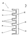
- the attachment element 24 according to the invention has a guide surface 16, which are aligned with the guide surface 22 in the direction of its curvature is.
- the attachment element 24 has the width of the sheet guide cylinder 4, 5 a plurality of tines 17 arranged on a bar 19 Prongs 17 are arranged at a defined distance from one another and form thus free spaces 18 through the at least one gripper system 13, which none Arch leads, can pass.
- the strip 19 is connected by means of connecting means 20, e.g. Screw connections, releasably attached to the sheet guiding device 11.
- connecting means 20 e.g. Screw connections
- the rounding 21 can relate to the prongs 17 associated side of the bar 19 extend.
- the curves 21 preferably point a radius of 1.0 to 5.0 mm.
- the mode of operation is as follows: In the transfer area 10 a rotating Sheet guide cylinder 4 (impression cylinder) of the sheet in the conveying direction 12 hand over the rotating sheet guide cylinder 5 (Transferter) with the front edge. The sheet adheres to the over region 10 with part of the Bow on the outer surface of the sheet guide cylinder 4.
- the comb-shaped Attachment element 17 projects close to transfer area 10 and "peels" the rest Bow from the outer surface of the sheet guide cylinder 4.
- the arc is guided approximately on a sheet conveying plane 15 shown in FIG. 2 and slides in this sheet conveying plane 15 along the guide surfaces 16 and 22.
- the sheet guiding cylinder 4 By “peeling" the sheet guiding cylinder 4 and preferably in combination with the curves 21, possible damage to the sheet is avoided and the sheet is guided evenly.
- the comb-shaped attachment element 24 can, if necessary, be replaced by a further attachment element 24, for example with a different radius of the curves 21.
- the attachment element 24 can also be arranged firmly on the sheet guiding device 11.
Landscapes
- Supply, Installation And Extraction Of Printed Sheets Or Plates (AREA)
- Feeding Of Articles By Means Other Than Belts Or Rollers (AREA)
Description
Die Erfindung bezieht sich auf eine Bogenführungseinrichtung mit einem Aufsatzelement, welches dem Übergabebereich von zwei Greifersystemen zugeordnet ist. Die Greifersysteme können dabei an einem Bogenführungszylinder und/oder einem umlaufenden Kettensystem angeordnet sein.
Der Vorteil der Ausbildung besteht darin, daß das erfindungsgemäße Aufsatzelement - ohne Beschädigungen im Bereich der Bogenhinterkante zu verursachen - möglichst nahe in den Übergabebereich hineinragt. Damit hat das Aufsatzelement eine Rakelfunktion zum benachbarten Bogenführungszylinder. Weiterhin ist das Aufsatzelement lösbar mit der feststehenden Bogenführungseinrichtung verbunden, so daß das Aufsatzelement auch in bereits vorhandene Bogenführungseinrichtungen (beispielsweise gem. EP 0156173 B 1) nachrüstbar ist. Ein Wechseln derartiger Luftversorgungskästen entfällt. Weiterhin ist es vorteilhaft, daß das Aufsetzelement leicht austauschbar ist und somit entsprechend des zu verarbeitenden Bedruckstoffes, z.B. in der Anzahl oder Form der Zinken, dem Flächengewicht und damit dem Bogenverlauf anpaßbar ist. Ein weiterer Vorteil ist darin begründet, daß zumindest die Zinken eine umlaufende Rundung, zumindest dem Bedruckstoff zugewandt, aufweisen. Dadurch wird ein mögliches Einreißen im Bereich der Bogenhinterkante vermieden.
In einer weiteren Ausbildung ist das Aufsatzelement oberhalb eines Bogenfülhrungszylinders dem Übergabebereich zweier Greifersysteme nachgeordnet und gegen die Förderrichtung gerichtet.
- Fig. 1
- eine Bogenrotationsdruckmaschine in Reihenbauweise
- Fig. 2
- eine Bogenführungseinrichtung im Übergabebereich
- Fig. 3
- ein Detail der Bogenführungseinrichtung.
Ist die Verarbeitung eines Bedruckstoffes mit zum vorher verarbeiteten Bedruckstoff unterschiedlichem Flächengewicht vorgesehen, so ist bei Bedarf das kammförmige Aufsatzelement 24 durch ein weiteres Aufsatzelement 24, beispielsweise mit unterschiedlichem Radius der Rundungen 21, austauschbar. Alternativ kann das Aufsatzelement 24 auch fest an der Bogenführungseinrichtung 11 angeordnet werden.
- 1
- Druckwerk
- 2
- Plattenzylinder
- 3
- Gummituchzylinder
- 4
- Bogenführungszylinder
- 5
- Bogenführungszylinder
- 6
- Formzylinder
- 7
- Dosiersystem
- 8
- Lackwerk
- 9
- Ausleger
- 10
- Übergabebereich
- 11
- Bogenführungseinrichtung
- 12
- Förderrichtung
- 13
- Greifersystem
- 14
- Kettensystem
- 15
- Bogenförderebene
- 16
- Leitfläche
- 17
- Zinken
- 18
- Freiraum
- 19
- Leiste
- 20
- Verbindungsmittel
- 21
- Rundung
- 22
- Leitfläche
- 23
- Öffnung
- 24
- Aufsatzelement
Claims (7)
- Bogenführungseinrichtung mit einer Leitfläche in einer Druckmaschine, welche einem Übergabebereich von zwei Greifersystemen zugeordnet ist,
dadurch gekennzeichnet,daß ein kammförmiges Aufsatzelement (24) an der Bogenführungseinrichtung (11) zwischen deren Leitfläche (22) und dem Übergabebereich (10) angeordnet ist.daß das Aufsatzelement (24) eine Leitfläche (16) aufweist, welche mit der Leitfläche (22) in deren Krümmungssinn fluchtend ist, unddaß das Aufsatzelement (24) eine Vielzahl von an einer Leiste (19) angeordneter Zinken (17) aufweist, wobei die Zinken (17) in untereinander Freiräume (18) bildende Abständen angeordnet sind, um ein Durchlaufen von wenigstens einem Greifersystem (13) zu gewährleisten. - Bogenführungseinrichtung nach Anspruch 1,
dadurch gekennzeichnet, daß zumindest die Zinken (17) eine umlaufende Rundung (21) aufweisen - Bogenführungseinrichtung nach Anspruch 1 und 2,
dadurch gekennzeichnet, daß die Rundung (21) einen Radius von 1,0 bis 5,0 mm aufweist. - Bogenführungseinrichtung nach Anspruch 1 und 2,
dadurch gekennzeichnet, daß das Aufsatzelement (24) im Bogenabgang dem Übergabebereich (10) in Förderrichtung (12) nachgeordnet ist. - Bogenführungseinrichtung nach Anspruch 1 und 2,
dadurch gekennzeichnet, daß das Aufsatzelement (24) im Bogenaufgang dem Übergabebereich (10) in Förderrichtung (12) vorgeordnet ist. - Bogenführungseinrichtung nach Anspruch 1 und 2,
dadurch gekennzeichnet, daß das Aufsatzelement (24) oberhalb eines Bogenführungszylinders (4,5) dem Übergabebereich (10) entgegen der Förderrichtung (12) nachgeordnet ist. - Bogenführungseinrichtung nach Anspruch 1,
dadurch gekennzeichnet, daß das Aufsatzelement (24) lösbar an der Bogenführungseinrichtung (11) angeordnet ist.
Applications Claiming Priority (2)
| Application Number | Priority Date | Filing Date | Title |
|---|---|---|---|
| DE29720989U DE29720989U1 (de) | 1997-11-27 | 1997-11-27 | Bogenführungseinrichtung mit einer Leitfläche in einer Druckmaschine |
| DE29720989U | 1997-11-27 |
Publications (2)
| Publication Number | Publication Date |
|---|---|
| EP0922576A1 EP0922576A1 (de) | 1999-06-16 |
| EP0922576B1 true EP0922576B1 (de) | 2001-11-28 |
Family
ID=8049173
Family Applications (1)
| Application Number | Title | Priority Date | Filing Date |
|---|---|---|---|
| EP98121692A Expired - Lifetime EP0922576B1 (de) | 1997-11-27 | 1998-11-13 | Bogenführungseinrichtung mit einer Leitfläche in einer Druckmaschine |
Country Status (4)
| Country | Link |
|---|---|
| EP (1) | EP0922576B1 (de) |
| JP (1) | JPH11221904A (de) |
| AT (1) | ATE209569T1 (de) |
| DE (2) | DE29720989U1 (de) |
Cited By (3)
| Publication number | Priority date | Publication date | Assignee | Title |
|---|---|---|---|---|
| EP1679187A2 (de) | 2005-01-07 | 2006-07-12 | Heidelberger Druckmaschinen Aktiengesellschaft | Bogenleiteinrichtung mit elektrisch isoliertem, kammförmigem Rand |
| DE102022104772A1 (de) | 2022-03-01 | 2023-09-07 | Heidelberger Druckmaschinen Aktiengesellschaft | Vorrichtung zum Leiten von Druckbogen in einer Druckmaschine |
| DE102023103112B3 (de) | 2023-02-09 | 2023-12-14 | Heidelberger Druckmaschinen Aktiengesellschaft | Vorrichtung zum Leiten von Bogen in einer Druckmaschine |
Families Citing this family (3)
| Publication number | Priority date | Publication date | Assignee | Title |
|---|---|---|---|---|
| DE29817317U1 (de) * | 1998-09-26 | 1998-11-19 | MAN Roland Druckmaschinen AG, 63075 Offenbach | Bogenführungseinrichtung mit einer Führungsfläche in einer Druckmaschine |
| DE10207073B4 (de) * | 2002-02-20 | 2005-11-24 | Koenig & Bauer Ag | Vorrichtung zum Transport von Bogen mit einem Bogenleitelement |
| EP1352738A3 (de) * | 2002-04-08 | 2004-08-04 | Komori Corporation | Gerät zum Führen von Bögen |
Family Cites Families (3)
| Publication number | Priority date | Publication date | Assignee | Title |
|---|---|---|---|---|
| DE3411029A1 (de) * | 1984-03-24 | 1985-10-03 | M.A.N.- Roland Druckmaschinen AG, 6050 Offenbach | Vorrichtung zum fuehren von ein- und beidseitig bedruckten bogen |
| DE4424964C2 (de) * | 1994-07-15 | 2001-03-15 | Koenig & Bauer Ag | Bogenleiteinrichtung zum Wenden von Bogen |
| DE19546046A1 (de) * | 1995-12-09 | 1997-06-12 | Heidelberger Druckmasch Ag | Bogenführsystem für eine Druckmaschine |
-
1997
- 1997-11-27 DE DE29720989U patent/DE29720989U1/de not_active Expired - Lifetime
-
1998
- 1998-11-13 EP EP98121692A patent/EP0922576B1/de not_active Expired - Lifetime
- 1998-11-13 DE DE59802226T patent/DE59802226D1/de not_active Expired - Fee Related
- 1998-11-13 AT AT98121692T patent/ATE209569T1/de not_active IP Right Cessation
- 1998-11-27 JP JP10337547A patent/JPH11221904A/ja active Pending
Cited By (3)
| Publication number | Priority date | Publication date | Assignee | Title |
|---|---|---|---|---|
| EP1679187A2 (de) | 2005-01-07 | 2006-07-12 | Heidelberger Druckmaschinen Aktiengesellschaft | Bogenleiteinrichtung mit elektrisch isoliertem, kammförmigem Rand |
| DE102022104772A1 (de) | 2022-03-01 | 2023-09-07 | Heidelberger Druckmaschinen Aktiengesellschaft | Vorrichtung zum Leiten von Druckbogen in einer Druckmaschine |
| DE102023103112B3 (de) | 2023-02-09 | 2023-12-14 | Heidelberger Druckmaschinen Aktiengesellschaft | Vorrichtung zum Leiten von Bogen in einer Druckmaschine |
Also Published As
| Publication number | Publication date |
|---|---|
| JPH11221904A (ja) | 1999-08-17 |
| DE59802226D1 (de) | 2002-01-10 |
| DE29720989U1 (de) | 1998-01-08 |
| EP0922576A1 (de) | 1999-06-16 |
| ATE209569T1 (de) | 2001-12-15 |
Similar Documents
| Publication | Publication Date | Title |
|---|---|---|
| DE4242730C2 (de) | Bogenausleger einer Druckmaschine | |
| EP1147893B2 (de) | Bogen-Rotationsdruckmaschine mit einem Multifunktionsmodul | |
| DE4447963B4 (de) | Einrichtung zum berührungsfreien Führen bogenförmigen Materials | |
| EP0755783B1 (de) | Druckmaschine mit geradliniger Substratführung und Wendeeinrichtungen dafür | |
| DE29501537U1 (de) | Bogenleiteinrichtung mit Luftversorgungskästen | |
| DE19631598C2 (de) | Pneumatische Bogenführungsvorrichtung in einer Druckmaschine | |
| EP0922576B1 (de) | Bogenführungseinrichtung mit einer Leitfläche in einer Druckmaschine | |
| EP1028077B1 (de) | Bogenführungseinrichtung für eine Druckmaschine | |
| DE29817317U1 (de) | Bogenführungseinrichtung mit einer Führungsfläche in einer Druckmaschine | |
| DE10060557B4 (de) | Bogenleiteinrichtung in einer Rotationsdruckmaschine | |
| EP0924069B1 (de) | Bogenführungseinrichtung in einer Druckmaschine | |
| EP1872946A2 (de) | Bogenführungszylinder mit Aufzug in einer Verarbeitungsmaschine | |
| DE2137115A1 (de) | Bogenfoerdereinrichtung | |
| EP0922577A1 (de) | Bogenführungseinrichtung in einer Druckmaschine | |
| DE102005016783B4 (de) | Bogenbremse | |
| DE10157566B4 (de) | Bogenleiteinrichtung mit einer Führungsfläche in einer Druckmaschine | |
| CH651501A5 (en) | Sheet-fed rotary printing machine having at least one printing unit | |
| EP1834912B1 (de) | Bogenverarbeitungsmaschine mit einer Leiteinrichtung zum schwebenden Führen von Bogenmaterial | |
| DE10323468A1 (de) | Bogen verarbeitende Maschine mit einer pneumatischen Bogenleitvorrichtung | |
| DE10255948B3 (de) | Greifersystemkörper zum Fördern von Bogen in Bogendruckmaschinen | |
| DE102014221460B4 (de) | Vorrichtung zum Trocknen von Bogen | |
| EP0699528B1 (de) | Bogenführender Trommelkörper für eine Druckmaschine | |
| DE102005012527A1 (de) | Anlegeeinheit für eine Bogenverarbeitungsmaschine, Bogenverarbeitungsmaschine und Verfahren zum Anlegen von Bogen | |
| EP0444507B1 (de) | Weiche in einer Rollenrotationsdruckmaschine | |
| DE19752492C2 (de) | Bogenführungseinrichtung in einer Druckmaschine |
Legal Events
| Date | Code | Title | Description |
|---|---|---|---|
| PUAI | Public reference made under article 153(3) epc to a published international application that has entered the european phase |
Free format text: ORIGINAL CODE: 0009012 |
|
| AK | Designated contracting states |
Kind code of ref document: A1 Designated state(s): AT DE FR GB |
|
| AX | Request for extension of the european patent |
Free format text: AL;LT;LV;MK;RO;SI |
|
| 17P | Request for examination filed |
Effective date: 19990511 |
|
| AKX | Designation fees paid |
Free format text: AT DE FR GB |
|
| GRAG | Despatch of communication of intention to grant |
Free format text: ORIGINAL CODE: EPIDOS AGRA |
|
| GRAG | Despatch of communication of intention to grant |
Free format text: ORIGINAL CODE: EPIDOS AGRA |
|
| GRAH | Despatch of communication of intention to grant a patent |
Free format text: ORIGINAL CODE: EPIDOS IGRA |
|
| GRAH | Despatch of communication of intention to grant a patent |
Free format text: ORIGINAL CODE: EPIDOS IGRA |
|
| 17Q | First examination report despatched |
Effective date: 20010315 |
|
| GRAA | (expected) grant |
Free format text: ORIGINAL CODE: 0009210 |
|
| AK | Designated contracting states |
Kind code of ref document: B1 Designated state(s): AT DE FR GB |
|
| REF | Corresponds to: |
Ref document number: 209569 Country of ref document: AT Date of ref document: 20011215 Kind code of ref document: T |
|
| GBT | Gb: translation of ep patent filed (gb section 77(6)(a)/1977) |
Effective date: 20011128 |
|
| REG | Reference to a national code |
Ref country code: GB Ref legal event code: IF02 |
|
| ET | Fr: translation filed | ||
| REF | Corresponds to: |
Ref document number: 59802226 Country of ref document: DE Date of ref document: 20020110 |
|
| PLBE | No opposition filed within time limit |
Free format text: ORIGINAL CODE: 0009261 |
|
| STAA | Information on the status of an ep patent application or granted ep patent |
Free format text: STATUS: NO OPPOSITION FILED WITHIN TIME LIMIT |
|
| PGFP | Annual fee paid to national office [announced via postgrant information from national office to epo] |
Ref country code: AT Payment date: 20021029 Year of fee payment: 5 |
|
| PGFP | Annual fee paid to national office [announced via postgrant information from national office to epo] |
Ref country code: GB Payment date: 20021030 Year of fee payment: 5 |
|
| PGFP | Annual fee paid to national office [announced via postgrant information from national office to epo] |
Ref country code: FR Payment date: 20021104 Year of fee payment: 5 |
|
| 26N | No opposition filed | ||
| PG25 | Lapsed in a contracting state [announced via postgrant information from national office to epo] |
Ref country code: GB Free format text: LAPSE BECAUSE OF NON-PAYMENT OF DUE FEES Effective date: 20031113 Ref country code: AT Free format text: LAPSE BECAUSE OF NON-PAYMENT OF DUE FEES Effective date: 20031113 |
|
| GBPC | Gb: european patent ceased through non-payment of renewal fee |
Effective date: 20031113 |
|
| PG25 | Lapsed in a contracting state [announced via postgrant information from national office to epo] |
Ref country code: FR Free format text: LAPSE BECAUSE OF NON-PAYMENT OF DUE FEES Effective date: 20040730 |
|
| REG | Reference to a national code |
Ref country code: FR Ref legal event code: ST |
|
| PGFP | Annual fee paid to national office [announced via postgrant information from national office to epo] |
Ref country code: DE Payment date: 20061124 Year of fee payment: 9 |
|
| PG25 | Lapsed in a contracting state [announced via postgrant information from national office to epo] |
Ref country code: DE Free format text: LAPSE BECAUSE OF NON-PAYMENT OF DUE FEES Effective date: 20080603 |