EP0926648A2 - Emetteur HF à apprentisage possédant des capacités d'apprentissage expansées - Google Patents
Emetteur HF à apprentisage possédant des capacités d'apprentissage expansées Download PDFInfo
- Publication number
- EP0926648A2 EP0926648A2 EP98310123A EP98310123A EP0926648A2 EP 0926648 A2 EP0926648 A2 EP 0926648A2 EP 98310123 A EP98310123 A EP 98310123A EP 98310123 A EP98310123 A EP 98310123A EP 0926648 A2 EP0926648 A2 EP 0926648A2
- Authority
- EP
- European Patent Office
- Prior art keywords
- signal
- frequency
- controller
- coupled
- received
- Prior art date
- Legal status (The legal status is an assumption and is not a legal conclusion. Google has not performed a legal analysis and makes no representation as to the accuracy of the status listed.)
- Granted
Links
- 230000004044 response Effects 0.000 claims description 17
- 230000004913 activation Effects 0.000 claims description 12
- 230000000903 blocking effect Effects 0.000 claims description 3
- 230000003362 replicative effect Effects 0.000 abstract 1
- 239000003990 capacitor Substances 0.000 description 20
- 238000012549 training Methods 0.000 description 16
- 230000015572 biosynthetic process Effects 0.000 description 9
- 238000003786 synthesis reaction Methods 0.000 description 9
- 230000005540 biological transmission Effects 0.000 description 8
- 239000013078 crystal Substances 0.000 description 3
- 230000006870 function Effects 0.000 description 3
- 230000008054 signal transmission Effects 0.000 description 3
- 238000010276 construction Methods 0.000 description 2
- 238000010586 diagram Methods 0.000 description 2
- 230000007246 mechanism Effects 0.000 description 2
- 239000004065 semiconductor Substances 0.000 description 2
- 229910000859 α-Fe Inorganic materials 0.000 description 2
- 239000000919 ceramic Substances 0.000 description 1
- 238000004891 communication Methods 0.000 description 1
- 239000004020 conductor Substances 0.000 description 1
- 230000003247 decreasing effect Effects 0.000 description 1
- 238000013461 design Methods 0.000 description 1
- 238000005516 engineering process Methods 0.000 description 1
- 230000007274 generation of a signal involved in cell-cell signaling Effects 0.000 description 1
- 238000000034 method Methods 0.000 description 1
- 238000012986 modification Methods 0.000 description 1
- 230000004048 modification Effects 0.000 description 1
- 238000012545 processing Methods 0.000 description 1
- 230000004043 responsiveness Effects 0.000 description 1
- 238000012795 verification Methods 0.000 description 1
Images


Classifications
-
- G—PHYSICS
- G08—SIGNALLING
- G08C—TRANSMISSION SYSTEMS FOR MEASURED VALUES, CONTROL OR SIMILAR SIGNALS
- G08C19/00—Electric signal transmission systems
- G08C19/16—Electric signal transmission systems in which transmission is by pulses
- G08C19/28—Electric signal transmission systems in which transmission is by pulses using pulse code
-
- G—PHYSICS
- G07—CHECKING-DEVICES
- G07C—TIME OR ATTENDANCE REGISTERS; REGISTERING OR INDICATING THE WORKING OF MACHINES; GENERATING RANDOM NUMBERS; VOTING OR LOTTERY APPARATUS; ARRANGEMENTS, SYSTEMS OR APPARATUS FOR CHECKING NOT PROVIDED FOR ELSEWHERE
- G07C9/00—Individual registration on entry or exit
- G07C9/00174—Electronically operated locks; Circuits therefor; Nonmechanical keys therefor, e.g. passive or active electrical keys or other data carriers without mechanical keys
- G07C9/00857—Electronically operated locks; Circuits therefor; Nonmechanical keys therefor, e.g. passive or active electrical keys or other data carriers without mechanical keys where the code of the data carrier can be programmed
-
- G—PHYSICS
- G08—SIGNALLING
- G08C—TRANSMISSION SYSTEMS FOR MEASURED VALUES, CONTROL OR SIMILAR SIGNALS
- G08C17/00—Arrangements for transmitting signals characterised by the use of a wireless electrical link
- G08C17/02—Arrangements for transmitting signals characterised by the use of a wireless electrical link using a radio link
-
- G—PHYSICS
- G07—CHECKING-DEVICES
- G07C—TIME OR ATTENDANCE REGISTERS; REGISTERING OR INDICATING THE WORKING OF MACHINES; GENERATING RANDOM NUMBERS; VOTING OR LOTTERY APPARATUS; ARRANGEMENTS, SYSTEMS OR APPARATUS FOR CHECKING NOT PROVIDED FOR ELSEWHERE
- G07C9/00—Individual registration on entry or exit
- G07C9/00174—Electronically operated locks; Circuits therefor; Nonmechanical keys therefor, e.g. passive or active electrical keys or other data carriers without mechanical keys
- G07C2009/00753—Electronically operated locks; Circuits therefor; Nonmechanical keys therefor, e.g. passive or active electrical keys or other data carriers without mechanical keys operated by active electrical keys
- G07C2009/00769—Electronically operated locks; Circuits therefor; Nonmechanical keys therefor, e.g. passive or active electrical keys or other data carriers without mechanical keys operated by active electrical keys with data transmission performed by wireless means
- G07C2009/00793—Electronically operated locks; Circuits therefor; Nonmechanical keys therefor, e.g. passive or active electrical keys or other data carriers without mechanical keys operated by active electrical keys with data transmission performed by wireless means by Hertzian waves
-
- G—PHYSICS
- G07—CHECKING-DEVICES
- G07C—TIME OR ATTENDANCE REGISTERS; REGISTERING OR INDICATING THE WORKING OF MACHINES; GENERATING RANDOM NUMBERS; VOTING OR LOTTERY APPARATUS; ARRANGEMENTS, SYSTEMS OR APPARATUS FOR CHECKING NOT PROVIDED FOR ELSEWHERE
- G07C9/00—Individual registration on entry or exit
- G07C9/00174—Electronically operated locks; Circuits therefor; Nonmechanical keys therefor, e.g. passive or active electrical keys or other data carriers without mechanical keys
- G07C9/00817—Electronically operated locks; Circuits therefor; Nonmechanical keys therefor, e.g. passive or active electrical keys or other data carriers without mechanical keys where the code of the lock can be programmed
- G07C2009/00849—Electronically operated locks; Circuits therefor; Nonmechanical keys therefor, e.g. passive or active electrical keys or other data carriers without mechanical keys where the code of the lock can be programmed programming by learning
-
- G—PHYSICS
- G07—CHECKING-DEVICES
- G07C—TIME OR ATTENDANCE REGISTERS; REGISTERING OR INDICATING THE WORKING OF MACHINES; GENERATING RANDOM NUMBERS; VOTING OR LOTTERY APPARATUS; ARRANGEMENTS, SYSTEMS OR APPARATUS FOR CHECKING NOT PROVIDED FOR ELSEWHERE
- G07C9/00—Individual registration on entry or exit
- G07C9/00174—Electronically operated locks; Circuits therefor; Nonmechanical keys therefor, e.g. passive or active electrical keys or other data carriers without mechanical keys
- G07C9/00896—Electronically operated locks; Circuits therefor; Nonmechanical keys therefor, e.g. passive or active electrical keys or other data carriers without mechanical keys specially adapted for particular uses
- G07C2009/00928—Electronically operated locks; Circuits therefor; Nonmechanical keys therefor, e.g. passive or active electrical keys or other data carriers without mechanical keys specially adapted for particular uses for garage doors
-
- G—PHYSICS
- G08—SIGNALLING
- G08C—TRANSMISSION SYSTEMS FOR MEASURED VALUES, CONTROL OR SIMILAR SIGNALS
- G08C2201/00—Transmission systems of control signals via wireless link
- G08C2201/20—Binding and programming of remote control devices
-
- G—PHYSICS
- G08—SIGNALLING
- G08C—TRANSMISSION SYSTEMS FOR MEASURED VALUES, CONTROL OR SIMILAR SIGNALS
- G08C2201/00—Transmission systems of control signals via wireless link
- G08C2201/60—Security, fault tolerance
- G08C2201/62—Rolling code
Definitions
- the present invention generally relates to trainable transmitters, and more particularly relates to vehicle-installed trainable transmitters capable of learning the carrier frequency, modulation scheme, and data code of a received radio frequency (RF) signal.
- RF radio frequency
- Trainable transmitters are known that are capable of learning the RF carrier frequency and code of a received RF signal for purposes of subsequently generating and transmitting a modulated RF signal having the learned characteristics on demand. Examples of such RF trainable transmitters are disclosed in United States Patent Nos. 5,583,485; 5,614,885; and 5,379,453 and Italian Patent No. 1,261,150. Such trainable transmitters were designed for implementation in a vehicle accessory such that they can be used to learn the characteristics of a signal transmitted from an original transmitter associated with a garage door opening mechanism. When used in this manner, the trainable transmitter can effectively replace the original transmitter while providing a clean, neat appearance in the interior of the vehicle. Further, these trainable transmitters can be trained to learn more than one activation signal thereby eliminating the need to have more than one transmitting device within a vehicle.
- trainable transmitters were developed that distinguish between different modulation schemes present in a received signal in order to encode such signals in different manners.
- Commonly-assigned United States Patent Nos. 5,479,155; 5,614,891; 5,661,804; and 5,686,903 disclose trainable transmitters having this added capability.
- the Federal Communications Commission enforces regulations pertaining to the permissible power output of RF signals within certain frequency bands.
- the FCC has designated the frequency band of 200 to 400 MHz for use by RF transmitters of a class including garage door opening transmitters. Because the FCC permits different power levels within this band based on the carrier frequency and duty cycle of the signal and because garage door opening transmitters may have carrier frequencies falling anywhere within this band, trainable transmitters of the type manufactured by the assignee preferably include variable attenuators or amplifiers for varying the amplitude of a transmitted signal in order to transmit the maximum power permitted by the FCC throughout the 200 to 400 MHz band. Trainable transmitters having this capability are described in commonly-assigned United States Patent Nos. 5,442,340; 5,479,155; 5,614,891; and 5,686,903.
- a trainable transmitter To enhance security of garage door opening mechanisms, manufacturers have implemented cryptographic algorithms in their original transmitters and receivers that transmit and respond to randomly varying codes. To enable a vehicle-installed trainable transmitter to effectively operate in such systems, a trainable transmitter was developed that has the capability of recognizing when a received signal has been originated from a transmitter that generates a code that varies with each transmission in accordance with a cryptographic algorithm. When such a variable code is recognized, the trainable transmitter determines which cryptographic algorithm is used to vary the code from one actuation to the next in order to generate and transmit the next code to which the receiver will respond. A trainable transmitter having this capability is disclosed in commonly-assigned United States Patent No. 5,661,804.
- Trainable transmitters of the type described above have found other applications and uses within a vehicle.
- the receiving circuitry in such trainable transmitters may be used to receive and respond to an RF signal transmitted from a remote keyless entry (RKE) key fob to lock and unlock the vehicle's doors and to arm and disarm the vehicle's security system.
- RKE remote keyless entry
- Such trainable transmitters are disclosed in commonly-assigned United States Patent Nos. 5,614,885; 5,619,190; 5,627,529; and 5,646,701.
- the receiving circuitry in a trainable transmitter may also be used to receive vehicle parameter data, such as tire pressure, from transmitters connected to parameter sensors that are mounted within the vehicle. Such an arrangement allows for various vehicle parameters to be monitored and displayed without requiring any additional wiring.
- WO 94/02920 discloses a trainable transmitter including two different transmitting antennas for transmitting signals in the two respective frequency bands, as well as a third antenna for receiving signals from within both frequency bands.
- Another problem relating to the transmission of signals in the two frequency bands arises from the fact that voltage controlled oscillators (VCO) used to generate a carrier signal at such frequencies, become extremely complex and expensive if required to generate carrier signals at frequencies over such a broad range.
- VCO voltage controlled oscillators
- the trainable transmitter disclosed in PCT Application No. WO 94/02920 uses two separate VCOs that may be used to generate the carrier signals within the lower and upper frequency bands.
- the use of two oscillators nonetheless adds to the expense of the device.
- garage door opening systems are sold that transmit, receive, and respond to frequency modulated (FM) RF signals. Because essentially all garage door opening systems sold in North America transmit, receive, and respond to amplitude modulated (AM) RF signals and because the trainable transmitters described above (with the exception of those described in PCT Application No. WO 94/02920 and Italian Patent No. 1,226,150) were developed primarily for use in North America, those trainable transmitters do not have the capacity to learn and retransmit an FM signal. The trainable transmitters disclosed in PCT Application No. WO 94/02920 and Italian Patent No. 1,261,150, do not have the capability of receiving, learning, and retransmitting an FM signal. Thus, the prior trainable transmitters are not capable of learning all the various signals used in European garage door opening systems.
- FM frequency modulated
- AM amplitude modulated
- trainable transmitters An additional problem in developing a trainable transmitter for use in Europe, is to provide the capability in the trainable transmitter to transmit the learned signals at the maximum power levels permitted under all the different regulations of the various countries within Europe.
- trainable transmitters only vary the amplitude of the transmitted signals based upon the regulations passed by the United States government (if the amplitude is varied at all), and the regulations imposed in many countries in Europe are different from those in the United States, such prior trainable transmitters do not account for these different regulations and therefore do not transmit signals at the maximum power levels allowed by each European country.
- An additional aspect of the invention is to provide a trainable transmitter for learning the characteristics of a received FM RF signal and for subsequently transmitting an FM RF signal having the learned characteristics to a remote device.
- the trainable transmitter comprises a receiver for receiving an FM RF signal, a controller coupled to the receiver for identifying and storing signal characteristics including the RF carrier frequency code of the received modulated RF signal, and a transmitting circuit coupled to the controller for receiving the stored signal characteristics and for generating and transmitting an FM RF signal having the learned signal characteristics.
- the trainable transmitter of the present invention may learn and retransmit both types of signals.
- a trainable transmitter constructed in accordance with the present invention comprises a receiver for receiving an activation signal, and a memory having a plurality of sets of amplitude control data stored therein, each set of amplitude control data including amplitude control data representing different permissible amplitude levels for different countries in which the trainable transmitter may be operated.
- the transmitter further includes means for allowing the selection of one of the sets of amplitude control data based upon the country in which the trainable transmitter is to be operated, and a controller operable in a learning mode and an operating mode.
- the controller is coupled to the receiver for generating and storing data corresponding to the RF carrier frequency and code of the received activation signal when in the learning mode.
- the controller provides output data which identifies the RF carrier frequency and code of the received activation signal and amplitude control data read from the selected set of amplitude control data stored in the memory.
- the transmitter further includes a signal generator coupled to the controller for receiving output data and for generating a modulated RF carrier signal representing the received activation signal.
- the trainable transmitter includes an amplitude control circuit coupled to the signal generator and to the controller for receiving amplitude control data from the controller to selectively control the amplitude of the modulated RF carrier signal received from the signal generator at an amplitude level indicated by the received amplitude control data, and for transmitting an amplitude-controlled output signal.
- a trainable transmitter constructed in accordance with the present invention comprises a receiver for receiving an RF signal, a controller coupled to the receiver for identifying the characteristics of the RF signal including an RF carrier frequency and code of the received RF signal. Additionally, the trainable transmitter includes a signal generating circuit coupled to the controller for receiving the stored signal characteristics and for generating and transmitting a modulated RF signal having the learned signal characteristics.
- the signal generating circuit includes an oscillating circuit for generating frequencies within a first higher frequency band and a frequency divider selectively coupled between an output terminal of the signal generating circuit and the oscillator to selectively reduce the frequency of the signal output from the signal generating circuit to frequencies within a second lower frequency band, the frequency band being selected by the controller.
- Trainable transmitter 43 may alternatively be permanently incorporated in a vehicle accessory such as a visor 51 (Fig. 3) or a rearview mirror assembly 53 (Fig. 4). Although trainable transmitter 43 has been shown as incorporated in a visor and mirror assembly and removably located in an overhead console compartment, trainable transmitter 43 could be permanently or removably located in the vehicle's instrument panel or any other suitable location within the vehicle's interior.
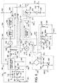
- Fig. 5 shows the electrical circuit 100 of trainable transmitter 43 in block and schematic form.
- Electrical circuit 100 includes a microprocessor-based controller 110 preferably including an 8-bit analog-to-digital (A/D) converter 112, a read-only memory (ROM) 114, and a random access memory (RAM) 116.
- A/D converter 112, ROM 114, and RAM 116 may be provided as separate elements connected to a microprocessor or may be formed within the microprocessor itself as shown in Fig. 5.
- a nonvolatile memory (NVM) 118 may be provided and connected separate from controller 110 or may be provided as an integral part of the microprocessor forming controller 110.
- a suitable controller for this purpose is microcontroller PIC 16C73A available from Microchip Technology Inc.
- NVM 118 preferably provides at least 4k bytes of RAM.
- controller 110 monitors how long the switch is actuated to determine whether it is to transmit a signal using the associated stored channel data or to enter a training mode whereby it learns and stores characteristics of a received RF signal A transmitted from an original transmitter 135 associated with a remotely actuated device 140 or 142.
- trainable transmitter circuit 100 is provided with a receiving antenna 130, which converts the received electromagnetic RF signal into an electrical RF signal that is output on line 131 to a mixer 136.
- receiving antenna 130 may be formed of a printed strip antenna 132 connected in series with an inductor 134.
- Mixer 136 mixes the received RF signal supplied on line 131 with a reference signal supplied on line 221.
- controller 110 controls a signal generator to generate the reference signal supplied to mixer 136 on line 221.
- the output of mixer 136 is provided on line 137 to the input of a wide-band bandpass filter 144.
- Wide-band bandpass filter 144 is preferably constructed to allow signals having frequencies at 455 kHz ⁇ 400 kHz to pass therethrough. Thus, wide-band bandpass filter 144 only outputs a signal when the difference between the frequency of the reference signal supplied to mixer 136 on line 221 and the RF carrier frequency of the received RF signal supplied to mixer 136 on line 131 is between 55 kHz and 855 kHz.
- a signal When a signal is output from wide-band bandpass filter 144, it is amplified by an amplifier 146 prior to being supplied to the input of a filter bypass switch 148.
- Filter bypass switch 148 is controlled by controller 110 via line 149 to selectively connect or bypass a narrow-band bandpass filter 150.
- Narrow-band bandpass filter 150 is preferably constructed to allow signals having frequencies of 455 kHz ⁇ 3 kHz to pass therethrough.
- the output of narrow-band bandpass filter 150 or the amplified output of wide-band bandpass filter 144 is supplied to the input of a limiter amplifier 152.
- limiter amplifier 152 is coupled to the input of a quadrature frequency discriminator 156, which converts an FM signal into an analog binary signal.
- mixer 136, amplifier 146, limiter amplifier 152, and quadrature frequency discriminator 156 are provided in the form of integrated circuit part No. SA625DK available from Phillips Semiconductor. With such an implementation, however, the ceramic discriminator typically used in such quadrature frequency discriminators (156) is connected external to such an integrated circuit.
- An FM data slicer 158 is coupled to the muted and unmuted audio outputs of quadrature frequency discriminator 156 to digitize the analog binary output signal prior to supplying the signal to controller 110 for analysis and storage.
- An AM data slicer 154 is provided to digitize a received signal strength indicator (RSSI) AM data output from integrated circuit part No. SA625DK.
- the RSSI signal is essentially an analog envelope signal corresponding to the amplitude of the received RF signal but having the carrier signal components removed.
- AM data slicer 154 digitizes the AM signal and supplies the digitized signal to controller 110 for further processing.
- the RSSI output is also supplied to A/D converter 112 in controller 110.
- controller 110 determines whether a received signal is AM or FM based upon the levels of the RSSI signals obtained from the received signal.
- trainable transmitter circuit 100 further includes a signal generator 159 for generating reference signals that are supplied to mixer 136.
- Signal generator 159 includes a signal generating circuit 200 and a frequency synthesis and control circuit 160.
- the primary component of signal generating circuit 200 is a VCO 202 that generates an RF signal having a frequency that is a function of the voltage level applied to its frequency control input terminal.
- the voltage level applied to the frequency control input terminal of VCO 202 is controlled by frequency synthesis and control circuit 160, which primarily includes a phase-locked loop (PLL) circuit 170.
- PLL phase-locked loop
- PLL circuit 170 receives frequency control data from controller 110 via line 165, and responds to this frequency control data by making any necessary adjustments to the voltage level applied to the frequency control input terminal of VCO 202 via line 169. More specifically, PLL circuit 170 divides the frequency of a reference signal supplied from a reference signal generating circuit 173 and the frequency of the VCO output received on a feedback line 167 in accordance with a ratio dictated by the frequency control data. PLL circuit 170 then compares the divided reference frequency with the divided VCO output frequency to determine whether the voltage applied on line 169 to the frequency control input terminal of VCO 202 needs to be increased or decreased to adjust the VCO's output frequency to correspond to the divided reference frequency.
- the reference signal generating circuit 173 includes a crystal oscillator 172, which preferably oscillates at a fixed frequency of 20 MHz, and a circuit 175 functioning as frequency deviation means for introducing frequency deviation for FM transmissions.
- the frequency deviation circuit 175 is not operated such that the frequency of the reference signal supplied to PLL circuit 170 is not altered.
- Frequency deviation circuit 175 includes first and second capacitors 174 and 176 coupled to opposite ends of crystal oscillator 172 and third and fourth capacitors 178 and 180 that are selectively coupled in series between respective first and second capacitors 174 and 176 and ground.
- first and second switches 182 and 184 are connected in parallel with capacitors 178 and 180. Switches 182 and 184 are driven between conductive and nonconductive states by frequency modulation data provided from controller 110 via lines 161 and 163, respectively.
- frequency modulation data provided from controller 110 via lines 161 and 163, respectively.
- capacitors 174 and 176 have a capacitance of 33 pF
- capacitor 178 has a capacitance of 22 pF
- capacitor 180 has a capacitance of 12 pF.
- controller 110 may obtain a deviation frequency of 4.6 kHz in the reference signal supplied to PLL circuit 170 by applying FM modulation data to switch 182 via line 161 and may obtain a 2.8 kHz deviation by applying the FM modulation data to switch 184 via line 163.
- deviation frequencies 7 kHz and 60 kHz for low-band and high-band signals, respectively, may be introduced in the RF signal to be transmitted.
- controller 110 determines which, if any, of lines 161 and 163 to apply FM modulation data, is described in detail below.
- frequency synthesis and control circuit 160 further includes a circuit coupled to the output of PLL circuit 170 including a capacitor 186 coupled between output line 169 and ground, a capacitor 190 coupled in series with a resistor 192 between output line 169 and ground, and a resistor 188 coupled between PLL circuit 170 and a node between capacitor 190 and resistor 192.
- the circuit coupled to the output of PLL circuit 170 is provided to prevent over-responsiveness of VCO 202 to the voltage level output from PLL circuit 170.
- PLL circuit is implemented using part No. LMX2337 available from National Semiconductor Corporation.
- signal generating circuit 200 includes VCO 202.
- VCO 202 is preferably constructed to output frequencies within the range of 250 MHz to 450 MHz. Given that this frequency range corresponds to the frequency range of conventional trainable transmitters used for transmitting signals in North America, any VCO used in such devices may be used to implement VCO 202 in accordance with this invention.
- a specific example of one such VCO is disclosed in United States Patent No. 5,686,903 issued on November 11, 1997.
- the signal generated by VCO 202 is supplied via line 209 to a switch 208 (Fig. 6) that is responsive to a frequency band select signal supplied by controller 110 on line 203.
- switch 208 When controller 110 selects the high frequency band (250 MHz to 450 MHz), switch 208 directly connects VCO output line 209 to signal generating circuit output line 201 such that the output signal of VCO 202 is directly output from signal generating circuit 200.
- signal generating circuit 200 is provided with a divide by 10 circuit 204 (also referred to herein as a frequency divider circuit), which receives the signal generated by VCO 202 and generates an output signal having a frequency that is one-tenth of that output from VCO 202.
- a divide by 10 circuit 204 also referred to herein as a frequency divider circuit
- signals may be generated by divide by 10 circuit 204 having frequencies anywhere in the range of 25 MHz to 45 MHz.
- a low pass filter 206 is preferably coupled to the output of divide by 10 circuit 204 to remove undesired harmonics that may be present in the output of circuit 204.
- controller 110 may select the lower (i.e ., 25 MHz to 45 MHz band) through the actuation of switch 208 to couple the output of low pass filter 206 to output line 201.
- the signal generated by signal generating circuit 200 is passed through an amplitude control circuit 210 and an amplitude modulation/filter circuit 220 prior to being applied via line 221 to an input of mixer 136.
- amplitude control circuit 210 is provided to adjust the amplitude of the signal generated by signal generating circuit 200 in response to amplitude control data supplied from controller 210 via line 213.
- controller 110 maintains the amplitude of the reference signal at a fixed optimum level for use by mixer 136.
- Amplitude modulation/filter circuit 220 is provided to modulate and filter the signal output from amplitude control circuit 210 on line 211 in response to AM modulation data generated by controller 110 on line 223.
- controller 110 generates an appropriate nonvarying signal and supplies this signal to amplitude modulation/filter circuit via line 223 to cause circuit 220 to pass the signal output from amplitude control circuit 210 on line 211 to pass directly through circuit 220 onto line 221 without being modulated.
- mixer 136 receives a reference signal during the training mode that is neither amplitude modulated by circuit 220 or FM by frequency deviation circuit 175.
- the transmitting circuitry of trainable transmitter circuit 100 includes the aforementioned frequency synthesis and control circuit 160, signal generating circuit 200, amplitude control circuit 210, and amplitude modulation/filter circuit 220, and additionally includes an antenna select switch 230, a high-band transmit antenna 240, and a low-band transmit antenna 250.
- controller 110 identifies the RF carrier frequency and data code of a received RF signal A and identifies whether the received signal is an AM or FM signal. Data representing the identified carrier frequency, data code, and modulation type are stored by controller 110 for subsequent use to transmit a signal having these characteristics during a transmit mode.
- controller 110 enters a transmit mode in response to the actuation of one of the switches of user interface 120 for a period that does not exceed a predetermined time threshold.
- controller 110 reads from NVM 118 the carrier frequency, data code, and modulation type stored for the channel associated with the actuated switch.
- controller 110 supplies frequency control data representing the desired carrier frequency to frequency synthesis and control circuit 160 via line 165 while holding switches 182 and 184 of frequency deviation circuit 175 in their current state by applying a non-altering voltage level on lines 161 and 163. Further, depending upon whether the carrier frequency to be generated is in the high or low band, controller 110 transmits the appropriate band selection signal to signal generating circuit 200 via line 203 to either bypass or output the signal from divide by 10 circuit 204. Thus, by applying the appropriate signals on lines 161, 163, 165, and 203, controller 110 may cause signal generator 159 to generate a signal having a nonvarying carrier frequency corresponding to the carrier frequency of an RF signal A received during the training mode.
- amplitude control circuit 210 is responsive to amplitude control data supplied from controller 110 on line 213 to adjust the amplitude of the signal received from signal generating circuit 200 via line 201.
- amplitude control circuit 210 may include a variable attenuator 212 and a buffer circuit including a resistor 214 coupled to line 213, a capacitor 218 coupled between a second terminal of resistor 214 and ground, and a buffer 216 coupled between the second terminal of resistor 214 and an attenuation level control terminal of attenuator 212.
- the amplitude control data delivered by controller 110 may be in the form of a pulse width modulated signal having a pulse width corresponding to the desired attenuation level.
- a plurality of sets of amplitude control data are preferably stored in NVM 118 for subsequent selection by an automobile dealer, distributor, or the vehicle owner.
- Each set of amplitude control data preferably corresponds to maximum amplitude levels for RF signals transmitted by this type of device that are permitted for one or more of the plurality of countries in which the device may be operated.
- the maximum permitted transmitted amplitude levels vary as a function of carrier frequency. Therefore, for a given set of amplitude control data, controller 110 may select the appropriate amplitude control data corresponding to the carrier frequency of the signal to be transmitted.
- user interface 120 may be configured to allow a user or automobile dealer to identify which country the device will be operated such that controller 110 may respond to such input by selecting and thereafter utilizing the appropriate set of amplitude control data.
- amplitude modulation/filter circuit 220 includes a modulator 222 in the form of an amplifier or gate that is capable of modulating the amplitude of the RF carrier signal input thereto on line 211 in response to an AM signal supplied from controller 110 on line 223.
- the modulated signal output from modulator 222 is provided to a low pass filter 224 to remove any undesired harmonics from the modulated signal.
- Low pass filter 224 preferably has a cut-off frequency of approximately 433 MHz.
- low pass filter 206 is provided in signal generating circuit 200, this filter is not utilized for high-band signal generation as a result of the bypass 209. Such a construction is preferable insofar as low pass filter 206 may then be configured to have a cut-off frequency of 57 MHz, for example, to more closely filter the lower frequencies passing therethrough without blocking any frequency signals intended to be transmitted in the higher frequency band.
- trainable transmitter circuit 100 utilizes two different transmitting antennas. Due to the need to transmit signals in the higher and lower frequency bands discussed above, two different types of antennas are utilized for transmitting in these respective bands in order to maximize the efficiency of signal transmission.
- Antenna select switch 230 is provided to selectively supply the modulated RF signal output from amplitude modulation/filter circuit 220 to either high-band transmit antenna 240 or low-band transmit antenna 250 via lines 231 or 233, respectively, in response to the frequency band select signal output from controller 110 on line 203.
- high-band transmit antenna 240 preferably includes a high-band loop antenna 242 having one terminal connected to input line 231 via a high-band transmit amplifier 244, and its other end coupled to ground via one or more capacitors 246 and 248.
- antenna 240 is a dynamically tunable antenna such that controller 110 may control the tuning of antenna 240 via line 241a to adjust the impedance of the antenna to most efficiently transmit a signal having the selected carrier frequency.
- antenna 242 may be tuned by selectively connecting capacitor 246 in parallel with capacitor 248 using a switch 245 that is responsive to a tuning control signal supplied from controller 110 via line 241a.
- antenna 240 is mounted in a visor, as illustrated in Fig. 3, a passive strip is preferably mounted in the visor in the manner disclosed in United States Patent No. 5,596,316 so as to increase the efficiency of transmission.
- Low-band transmit antenna 250 preferably includes a Ferrite core antenna 252 having one end connected to ground and the other end connected to the output of a low-band transmit amplifier 254, which has its input coupled to input line 233. Ferrite core antenna 252 is preferably used to transmit the signals having frequencies in the lower band due to its improved transmission performance characteristics with respect to signals having frequencies within the lower band. Like high-band transmit antenna 240, low-band transmit antenna 250 is preferably a dynamically tunable antenna. Such tuning may be accomplished by providing two capacitors 256 and 258, which may be selectively and independently coupled between the output of amplifier 254 and ground. To selectively couple such capacitors, respective switches 255a and 255b are coupled between the capacitors and ground that are responsive to control signals transmitted on lines 241b and 241c.
- controller 110 selects the required carrier frequency by supplying frequency selection data on line 165 and supplying a frequency band select signal on line 203.
- controller 110 reads the data code from memory and supplies the data code to either switch 182 or switch 184 in frequency synthesis and control circuit 160 via lines 161 or 163, respectively.
- Controller 110 determines which switch 182 or 184 to apply the data code based upon the frequency band in which the carrier frequency falls. For example, the data code is supplied to switch 182 for low-band transmissions and to switch 184 for high-band transmissions. By altering one of switches 182 and 184 between conductive and nonconductive states, an appropriate deviation frequency is introduced into the carrier signal generated by signal generating circuit 200 in correspondence with the data code read from memory.
- amplitude modulation filter circuit 220 is supplied with an AM modulation signal of constant value such that the signal generated by signal generating circuit 200 is not amplitude modulated.
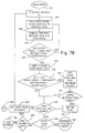
- controller 110 first clears RAM 116 (step 301) and performs an initial status inquiry of the hardware connected to controller 110 (step 303). Next, controller 110 determines whether one of the switches (44, 46, or 47) has been actuated or whether any other user input signal has otherwise been received from user interface 120 (step 305). If a switch has been actuated, controller 110 looks for and reads any data contained in nonvolatile memory 118 stored in a location thereof corresponding to the channel associated with the actuated switch (step 307).
- controller 110 determines whether the trainable transmitter has been trained with respect to the selected channel. If the trainable transmitter has been trained, controller 110 transmits a signal B1 or B2 depending upon the frequency band in which the carrier signal falls (step 311). The details of the manner in which trainable transmitter circuit 100 transmits a signal is described below with reference to Fig. 7D.
- controller 110 determines in step 313 whether the associated channel memory has stored therein any default signal characteristics data. If default signal characteristics data is stored in the associated channel memory, controller 110 then determines whether the stored default data is data for a system manufactured by The Chamberlain Group, Inc. (step 317) or a system manufactured by Keeloq (step 319). Based upon this determination, the trainable transmitter of the present invention may generate different signals based upon the stored characteristics and/or associated cryptographic algorithm for subsequently transmitting a signal in the manner described below with reference to Fig. 7D.
- controller 110 enters a training mode (step 321) in which it performs the operations described below with reference to Figs. 7B and 7C.
- a training mode step 321 in which it performs the operations described below with reference to Figs. 7B and 7C.
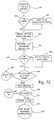
- controller 110 when controller 110 is in a training mode, it first transmits a signal on line 149 to filter bypass switch 148 causing switch 148 to bypass narrow-band bandpass filter 150 (step 323).
- IF intermediate frequency
- controller 110 varies the carrier frequency of the reference signal until it detects a signal output from amplifier 152 on line 153.
- controller 110 reads frequency data included in a table stored in NVM 118 and outputs this frequency data on lines 165 and 203 to cause the signal generator to generate a reference signal having a specified carrier frequency (step 325).
- the table of frequency data stored in NVM 118 preferably includes a list of frequency data corresponding to the carrier frequencies known to be used in commercially-available garage door opening systems. In Europe, such carrier frequencies are 27, 30, 40, 418, and 433 MHz. More precisely, the frequency data corresponds to carrier frequencies that are 455 kHz below the known carrier frequencies such that the carrier frequency of the generated reference signal is most likely to produce a detectable signal after passing through mixer 136 and filters 144 and 150.
- controller 110 While the reference signal is generated and supplied to mixer 136, controller 110 samples the RSSI signal supplied on line 153 to A/D converter 112. Controller 110 then records the peak values of the received RSSI signal as well as the peak/peak variations in the RSSI signal (step 327). In step 329, controller 110 determines whether data has been received by determining whether the recorded peaks of the RSSI signal exceed a threshold level or whether the peak/peak variation exceeds a threshold. If data is not present, controller 110 returns to step 325 to read the next set of frequency data from the frequency table stored in NVM 118. Steps 325-329 are repeated stepping through each of the frequencies in the frequency table until controller 110 determines in step 329 that data is present on line 153.
- controller 110 determines that data is present in step 329, controller 110 changes the frequency data applied on line 165 to cause the signal generator to generate a reference signal having a carrier frequency that is increased by 910 kHz (2 x 455 kHz) (step 331). If the previously-generated reference signal had a carrier frequency that was 455 kHz below the carrier frequency of the received RF signal A, data should once again be detected when the reference carrier frequency is increased to be 455 kHz above the carrier frequency of the received RF signal A since the difference between the frequencies of the reference signal and the received RF signal would still be 455 kHz. Thus, to confirm the first reference frequency was below, rather than above, the carrier frequency of the received RF signal, controller 110 determines in step 333 whether data is still present when the reference carrier frequency is increased to then potentially be above the carrier frequency of the received RF signal.
- controller 110 determines whether it has generated reference signals at each frequency identified in the frequency table stored in NVM 118 (step 335). If additional frequencies remain, controller 110 gets the next frequency from the table (step 337) and returns to steps 323-329 to continue to look for data at the frequencies listed in the frequency table. If controller 110 determines in step 335 that it has generated a reference signal corresponding to each frequency stored in the frequency table, it checks in step 345 whether the data flag has been set (discussed below). If the data flag has not been set, controller 110 determines in step 349 whether it has scanned through each of the frequencies identified in the frequency table a predetermined number of times.
- the trainable transmitter may be configured to scan through the entire list of frequencies in the frequency table twenty times before determining that no signal is present to which the device may be trained. If there are scans left to perform, controller 110 gets the next frequency from the table in step 337 and returns to steps 323-329 to detect the presence of data. If there are no scans left to perform, controller 110 signals user interface 120 to indicate to the user that training was unsuccessful and then controller 110 enters a low-power sleep state until it subsequently detects the actuation of a switch (step 351).
- controller 110 When controller 110 detects the presence of data in step 329 and subsequently verifies its presence in step 333 after increasing the reference signal frequency to one above that of the received RF signal, controller 110 sets a data flag and saves the maximum values of the recorded peaks of the RSSI signal along with the maximum peak-to-peak variation of the value of the RSSI signal (step 339).
- controller 110 determines whether the detected data signal is AM or FM by determining whether the received RSSI signal has large maximum peak values with relatively low peak-to-peak variation values. If the RSSI maximum peak value is high and the peak-to-peak variation level is low, controller 110 sets an FM flag in step 343 identifying the received signal as an FM signal. If the FM flag has not been set, the received signal is assumed to be an AM signal.
- controller 110 determines in step 335 whether it has scanned through all the bands of frequencies identified in the frequency table and then checks in step 345, whether the data flag has been set. If the data flag had been set, controller 110 advances to step 347 in which controller 110 executes a routine to more precisely identify the carrier frequency of the received RF signal A.
- controller 110 begins this next routine by first checking whether the FM flag has been set indicating that the received signal is an FM signal (step 353). If the signal is not an FM signal, controller 110 transmits a signal on line 149 to filter bypass switch 148 causing switch 148 to connect narrow-band bandpass filter 150 in series with wide-band bandpass filter 144 and amplifiers 146 and 152. Once the state of switch 148 has been changed in step 355 or when controller 110 determines in step 353 that an FM signal is present, controller 110 determines which frequency band is most likely to produce the signal by choosing that band that was selected when the maximum RSSI peaks were detected.
- controller 110 sweeps the entire selected band at much smaller incremental steps of frequency to identify the precise frequency at which the maximum peak values for the received RSSI signal (step 357) were detected.
- controller 110 increments the frequency of the reference signal 5 kHz at a time, whereas if the signal is an FM signal in the lower frequency band, controller 110 increments the reference carrier frequency at 1.25 kHz steps.
- controller 110 retunes signal generator 159 to the reference carrier frequency that produced the maximum peak levels of RSSI data as sensed at the input connected to line 153. Controller 110 then resets bypass switch 148 to bypass narrow-band bandpass filter 150 in step 363 provided the received signal is an AM signal as determined in step 361.
- controller 110 analyzes the data output from AM and FM data slicers 154 and 158 to determine whether a received data signal corresponds to a valid signal (step 365).
- This verification routine is preferably carried out by performing the steps of the VERIFY routine disclosed in United States Patent No. 5,661,804. If controller 110 determines in step 365 that the received data signal is not valid, controller 110 returns to step 337 (Fig. 7B) as indicated by connector 367, to select a different frequency from the frequency table in order to determine whether data is present at a different carrier frequency.
- controller 110 determines in step 365 that the received data signal is valid, controller 110 executes an ENCODE routine in step 369 in order to encode the received data signal for efficient storage in RAM 116 and NVM 118. Controller 110 selects the data signal received from FM data slicer 158 if it has determined that the received signal is an FM signal, and encodes the signal received from the AM data slicer 154 if the received signal is an AM signal. Preferably, controller 110 performs the ENCODE routine disclosed in United States Provisional Application No. 60/065,517 (unofficial) (Attorney Docket No. PRI01 PP-725) entitled METHOD AND APPARATUS FOR STORING A DATA ENCODED SIGNAL, filed on November 12, 1997, by Kurt A.
- Dykema in order to accommodate certain RF signals having long periods of dead time between data code words that are often transmitted by garage door opening transmitters commonly used in Europe.
- the entire disclosure of United States Provisional Application No. 60/065,517 (unofficial) (Attorney Docket No. PRI01 PP-725) is incorporated by reference herein.
- controller 110 determines that the encoding of the data signal was successful (step 371)
- controller 110 stores the encoded signal in NVM 118 (step 373) and transmits a signal to user interface 120 to cause user interface 120 to indicate to the user that training has been successfully completed.
- controller 110 transmits a signal thereto causing LED 48 to rapidly blink (step 375).
- controller 110 determines that the data signal was not successfully encoded, controller 110 returns to step 337 (Fig. 7B) as illustrated by connectors 367.
- controller 110 In addition to storing the encoded data signal in NVM 118, controller 110 also stores in association therewith, the frequency data last used to control signal generator 159. Such data includes the frequency control data output on line 165 as well as the frequency band select data output on line 203. Additionally, controller 110 stores a flag in association with the frequency data indicating whether the signal was identified as an AM or FM signal. As will be explained below, this stored information may be subsequently utilized to transmit a modulated signal having characteristics corresponding to those learned during the training mode for that particular channel. In a similar manner, trainable transmitter circuit 100 may be used to learn and store the signal characteristics of additional signals. Such additional signal characteristics would be stored in different locations of NVM 118 assigned to each different channel.
- controller 110 in the transmit mode, controller 110 first reads the frequency band select data stored in NVM 118 in association with the channel corresponding to the activated switch (step 401). If, in step 403, controller 110 determines that the carrier frequency of the signal to be generated is not in the lower frequency band, controller 110 outputs a high frequency band select signal on line 203 to bypass divide by 10 circuit 204 and to select high-band antenna 240 through manipulation of antenna select switch 230 (step 405).
- controller 110 determines that the carrier frequency of the signal to be generated lies in the lower frequency band, controller 110 outputs a low-frequency band select signal on line 203 to select the output from divide by 10 circuit 204 and to select low-band antenna 250 (step 407).
- controller 110 After selecting the appropriate antenna and configuring signal generating circuit 200 to the proper frequency band, controller 110 reads from the associated channel memory, the frequency control data representing the carrier frequency of the signal to be generated by VCO 202. Controller 110 then outputs this frequency control data on line 165 to PLL circuit 170 in frequency synthesis and control circuit 160 (step 409). In the manner described above, frequency synthesis and control circuit 160 and signal generating circuit 200 cooperate and respond to the signals supplied on lines 165 and 203 to generate a signal having a carrier frequency as specified by the frequency data supplied from controller 110.
- controller 110 reads and transmits the appropriate amplitude control data to amplitude control circuit 210 via line 213 in order to adjust the amplitude of the generated signal to the maximum level for a signal having the selected carrier frequency as permitted in the country in which the trainable transmitter is to be operated (step 411). Also, controller 110 outputs a frequency identification signal on line 241 to be received by antennas 240 and 250 for purposes of tuning these antennas to the optimum impedance level for transmission of a signal at the selected frequency. Subsequently, controller 110 reads the AM/FM flag for the selected channel (step 413) so that it may subsequently determine whether the signal to be transmitted is an AM or FM signal (step 415).
- controller 110 reads and decodes the encoded data signal from NVM 118 and supplies the data code to amplitude modulation/filter circuit 220 via line 223 (step 417).
- Amplitude modulation/filter circuit 220 responds to this data by modulating the amplitude of the signal received from amplitude control circuit 210.
- the modulated signal is then transmitted through antenna select switch 230 to the selected antenna 240 or 250.
- the selected one of antennas 240 and 250 transmits a signal B1 or B2, respectively, to remotely actuated devices 140 or 142.
- Two remotely actuated devices 140 and 142 are shown in Fig. 5 to illustrate the existence of different devices having receivers tuned to respond to frequencies in a lower frequency band (device 142) and frequencies in a higher frequency band (device 140).
- controller 110 determines in step 419 whether the carrier frequency is in the lower frequency band or in the higher frequency band. If the carrier frequency is in the lower frequency band, controller 110 reads and decodes the encoded data signal stored in NVM 118 and supplies the data signal to switch 182 via line 161. The data signal applied to switch 182 causes it to fluctuate between conductive and nonconductive states in response to the data signal thereby deviating the reference frequency supplied to PLL circuit 170. As the reference frequency received by PLL circuit 170 deviates between frequencies, PLL circuit responds by varying the voltage level applied on line 169 to VCO 202. VCO 202 responds to the varied voltage level by varying its output frequency.
- the data signal applied to switch 182 corresponds to the data signal obtained from frequency discriminator 156 and FM data slicer 158 when the received RF signal A is applied thereto, the frequency generated by VCO 202 during the transmit mode varies in the same manner as the received FM signal. Hence, a replicated FM signal may be generated and subsequently transmitted using a selected one of antennas 240 and 250.
- controller 110 determines in step 419 that the frequency is in the higher frequency band, controller 110 supplies the data signal read from NVM 118 to switch 184 via line 163 to introduce a different deviation frequency than that introduced when the data signal is supplied to switch 182 for frequencies in the lower frequency band.
- controller 110 supplies the data signal read from NVM 118 to switch 184 via line 163 to introduce a different deviation frequency than that introduced when the data signal is supplied to switch 182 for frequencies in the lower frequency band.
- additional switches and data supply lines may be provided to vary the reference frequency applied to PLL circuit 170 by differing amounts.
- controller 110 would analyze the identified carrier frequency and data code of the received RF signal A once they have been identified to determine whether they correspond to characteristics of signals typically transmitted from commercially-available systems that utilize a cryptographic algorithm to vary the transmitted codes.
- controller 110 may then select one of a plurality of cryptographic algorithms that may be stored in NVM 118, for use in generating the variable data code to be subsequently transmitted by the trainable transmitter. More specifically, with the identification of a particular cryptographic algorithm stored in memory and with an identification of the last transmitted code, controller 110 may determine the next code to be transmitted in accordance with that cryptographic algorithm upon actuation of an associated switch. The generated variable code is then supplied to either amplitude modulation/filter circuit 220 or frequency synthesis and control circuit 160 for modulation of a carrier signal having the learned carrier frequency.
Landscapes
- Physics & Mathematics (AREA)
- General Physics & Mathematics (AREA)
- Engineering & Computer Science (AREA)
- Computer Networks & Wireless Communication (AREA)
- Selective Calling Equipment (AREA)
- Transmitters (AREA)
Applications Claiming Priority (2)
| Application Number | Priority Date | Filing Date | Title |
|---|---|---|---|
| US993420 | 1997-12-18 | ||
| US08/993,420 US6091343A (en) | 1997-12-18 | 1997-12-18 | Trainable RF transmitter having expanded learning capabilities |
Publications (3)
| Publication Number | Publication Date |
|---|---|
| EP0926648A2 true EP0926648A2 (fr) | 1999-06-30 |
| EP0926648A3 EP0926648A3 (fr) | 2000-04-19 |
| EP0926648B1 EP0926648B1 (fr) | 2012-06-13 |
Family
ID=25539524
Family Applications (1)
| Application Number | Title | Priority Date | Filing Date |
|---|---|---|---|
| EP98310123A Expired - Lifetime EP0926648B1 (fr) | 1997-12-18 | 1998-12-10 | Emetteur HF à apprentisage possédant des capacités d'apprentissage expansées |
Country Status (2)
| Country | Link |
|---|---|
| US (1) | US6091343A (fr) |
| EP (1) | EP0926648B1 (fr) |
Cited By (13)
| Publication number | Priority date | Publication date | Assignee | Title |
|---|---|---|---|---|
| FR2808365A1 (fr) * | 2000-03-02 | 2001-11-02 | Trw Inc | Systeme et procede de telecommande d'une fonction |
| US6703941B1 (en) * | 1999-08-06 | 2004-03-09 | Johnson Controls Technology Company | Trainable transmitter having improved frequency synthesis |
| FR2850194A1 (fr) * | 2003-01-16 | 2004-07-23 | Somfy Sas | Recepteur d'ordres destines a la commande d'equipements et procede de communication entre un recepteur d'ordres et un emetteur d'ordres. |
| WO2004077721A3 (fr) * | 2003-02-21 | 2005-02-24 | Johnson Controls Tech Co | Systeme et procede de communication sans fil |
| FR2872948A1 (fr) * | 2004-07-06 | 2006-01-13 | Savoie Electronique Sa | Dispositif de telecommande de securite |
| WO2006134024A1 (fr) * | 2005-06-16 | 2006-12-21 | Johnson Controls Gmbh | Dispositif de commande a distance conçu pour un vehicule, et procede pour configurer un dispositif de commande a distance |
| WO2006102463A3 (fr) * | 2005-03-22 | 2006-12-28 | Johnson Controls Tech Co | Systeme et procede d'apprentissage d'un emetteur apte a l'apprentissage |
| GB2438726A (en) * | 2006-05-31 | 2007-12-05 | Lear Corp | Pulse width modulation control of RF signal power attenuation |
| WO2011054657A1 (fr) * | 2009-11-05 | 2011-05-12 | Hörmann KG Antriebstechnik | Détecteur radio pour la commande à distance d'un actionnement de porte, système d'actionnement de porte équipé de ce détecteur ainsi que procédé de transmission et de fonctionnement |
| US7970446B2 (en) | 1999-05-26 | 2011-06-28 | Johnson Controls Technology Company | Wireless control system and method |
| ITNA20100059A1 (it) * | 2010-12-09 | 2012-06-10 | Mido Elettronica S R L | Telecomando multicanale, multicodice a commutazione di banda. |
| EP2078230A4 (fr) * | 2006-08-24 | 2013-01-02 | Elbex Video Ltd | Procédé et appareil pour actionner à distance des instruments à partir d'interphones vidéo ou des terminaux de courses |
| US8380251B2 (en) | 1999-05-26 | 2013-02-19 | Johnson Controls Technology Company | Wireless communications system and method |
Families Citing this family (110)
| Publication number | Priority date | Publication date | Assignee | Title |
|---|---|---|---|---|
| US5910854A (en) | 1993-02-26 | 1999-06-08 | Donnelly Corporation | Electrochromic polymeric solid films, manufacturing electrochromic devices using such solid films, and processes for making such solid films and devices |
| US5668663A (en) | 1994-05-05 | 1997-09-16 | Donnelly Corporation | Electrochromic mirrors and devices |
| US6891563B2 (en) * | 1996-05-22 | 2005-05-10 | Donnelly Corporation | Vehicular vision system |
| US6124886A (en) | 1997-08-25 | 2000-09-26 | Donnelly Corporation | Modular rearview mirror assembly |
| US6172613B1 (en) | 1998-02-18 | 2001-01-09 | Donnelly Corporation | Rearview mirror assembly incorporating vehicle information display |
| US8294975B2 (en) | 1997-08-25 | 2012-10-23 | Donnelly Corporation | Automotive rearview mirror assembly |
| US6326613B1 (en) | 1998-01-07 | 2001-12-04 | Donnelly Corporation | Vehicle interior mirror assembly adapted for containing a rain sensor |
| US8288711B2 (en) | 1998-01-07 | 2012-10-16 | Donnelly Corporation | Interior rearview mirror system with forwardly-viewing camera and a control |
| US6445287B1 (en) | 2000-02-28 | 2002-09-03 | Donnelly Corporation | Tire inflation assistance monitoring system |
| US6329925B1 (en) | 1999-11-24 | 2001-12-11 | Donnelly Corporation | Rearview mirror assembly with added feature modular display |
| US6693517B2 (en) | 2000-04-21 | 2004-02-17 | Donnelly Corporation | Vehicle mirror assembly communicating wirelessly with vehicle accessories and occupants |
| US6477464B2 (en) | 2000-03-09 | 2002-11-05 | Donnelly Corporation | Complete mirror-based global-positioning system (GPS) navigation solution |
| US6978126B1 (en) * | 1999-06-07 | 2005-12-20 | Johnson Controls Technology Company | Transceiver with closed loop control of antenna tuning and power level |
| JP3576880B2 (ja) * | 1999-09-09 | 2004-10-13 | 日本電気株式会社 | 自動変調方式識別装置及び自動変調方式識別方法 |
| AU2001243285A1 (en) | 2000-03-02 | 2001-09-12 | Donnelly Corporation | Video mirror systems incorporating an accessory module |
| US7167796B2 (en) | 2000-03-09 | 2007-01-23 | Donnelly Corporation | Vehicle navigation system for use with a telematics system |
| US7370983B2 (en) | 2000-03-02 | 2008-05-13 | Donnelly Corporation | Interior mirror assembly with display |
| US6971021B1 (en) * | 2000-03-08 | 2005-11-29 | Rainbow Technologies, Inc. | Non-wire contact device application for cryptographic module interfaces |
| FR2808633B1 (fr) * | 2000-05-04 | 2002-07-26 | Sagem | Recepteur radio courte portee multibande pour donnees de vehicule automobile |
| US6339384B1 (en) | 2000-11-13 | 2002-01-15 | Robert Valdes-Rodriguez | Toll booth credit device |
| US6563474B2 (en) * | 2000-12-21 | 2003-05-13 | Lear Corporation | Remote access device having multiple inductive coil antenna |
| WO2002062623A2 (fr) | 2001-01-23 | 2002-08-15 | Donnelly Corporation | Systeme d'eclairage ameliore destine a un vehicule |
| US7581859B2 (en) | 2005-09-14 | 2009-09-01 | Donnelly Corp. | Display device for exterior rearview mirror |
| US7255451B2 (en) | 2002-09-20 | 2007-08-14 | Donnelly Corporation | Electro-optic mirror cell |
| US6847303B2 (en) * | 2001-05-07 | 2005-01-25 | Marantec America Corporation | Multifrequency garage door opener |
| US7057494B2 (en) * | 2001-08-09 | 2006-06-06 | Fitzgibbon James J | Method and apparatus for a rolling code learning transmitter |
| US8218608B2 (en) * | 2001-09-05 | 2012-07-10 | Lear Corporation | Self-tuning transmitter |
| US20030078685A1 (en) * | 2001-10-19 | 2003-04-24 | Taddy Shao | Intellegent transmitter receiver system and its operation method |
| US7167076B2 (en) | 2001-12-19 | 2007-01-23 | Lear Corporation | Universal garage door operating system and method |
| DE10207295A1 (de) * | 2002-02-21 | 2003-09-04 | Arvinmeritor Gmbh | Karosserieanbauteil und Verfahren zu seiner Herstellung |
| US7173514B2 (en) * | 2002-03-15 | 2007-02-06 | Wayne-Dalton Corp. | Operator for a movable barrier and method of use |
| US6963267B2 (en) | 2002-03-15 | 2005-11-08 | Wayne-Dalton Corporation | Operator for a movable barrier and method of use |
| JP2003303388A (ja) * | 2002-04-11 | 2003-10-24 | Pacific Ind Co Ltd | タイヤ状態監視装置の送信機及びタイヤ状態監視装置 |
| US20030197594A1 (en) * | 2002-04-22 | 2003-10-23 | Johnson Controls Technology Company | System and method for wireless control of home electronic systems based on location |
| US20030197595A1 (en) * | 2002-04-22 | 2003-10-23 | Johnson Controls Technology Company | System and method for wireless control of multiple remote electronic systems |
| US6918674B2 (en) | 2002-05-03 | 2005-07-19 | Donnelly Corporation | Vehicle rearview mirror system |
| US6990317B2 (en) | 2002-05-28 | 2006-01-24 | Wireless Innovation | Interference resistant wireless sensor and control system |
| AU2003237424A1 (en) | 2002-06-06 | 2003-12-22 | Donnelly Corporation | Interior rearview mirror system with compass |
| US7329013B2 (en) | 2002-06-06 | 2008-02-12 | Donnelly Corporation | Interior rearview mirror system with compass |
| US20040000062A1 (en) * | 2002-06-28 | 2004-01-01 | Johnson Controls Technology Company | Compass display for a vehicle |
| US7565006B2 (en) | 2002-08-21 | 2009-07-21 | Gentex Corporation | Image acquisition and processing methods for automatic vehicular exterior lighting control |
| US7310177B2 (en) | 2002-09-20 | 2007-12-18 | Donnelly Corporation | Electro-optic reflective element assembly |
| WO2004103772A2 (fr) | 2003-05-19 | 2004-12-02 | Donnelly Corporation | Assemblage de retroviseur pour vehicule |
| AU2003278863A1 (en) | 2002-09-20 | 2004-04-08 | Donnelly Corporation | Mirror reflective element assembly |
| US7911358B2 (en) * | 2002-10-08 | 2011-03-22 | Johnson Controls Technology Company | System and method for enrollment of a remotely controlled device in a trainable transmitter |
| EP1554706A1 (fr) * | 2002-10-08 | 2005-07-20 | Johnson Controls Technology Company | Systeme et procede de commande sans fil de systemes electroniques distants comprenant une fonctionnalite fondee sur la localisation |
| US8531266B2 (en) * | 2002-10-18 | 2013-09-10 | Johnson Controls Technology Company | System and method for providing an in-vehicle transmitter having multi-colored LED |
| WO2004036526A2 (fr) * | 2002-10-18 | 2004-04-29 | Johnson Controls Technology Company | Systeme et procede pour la reception de signal d'etat en mode sans fil dans un vehicule, depuis un systeme electronique distant. |
| US8174357B2 (en) * | 2002-11-08 | 2012-05-08 | Johnson Controls Technology Company | System and method for training a transmitter to control a remote control system |
| WO2004077729A2 (fr) | 2003-02-21 | 2004-09-10 | Johnson Controls Technology Company | Emetteur/recepteur apte a l'apprentissage et procede de determination de la frequence d'un signal de commande appris |
| JP2006509933A (ja) * | 2002-11-08 | 2006-03-23 | ジョンソン コントロールズ テクノロジー カンパニー | 養成可能なトランシーバシステム |
| US7116242B2 (en) * | 2002-11-27 | 2006-10-03 | Lear Corporation | Programmable transmitter and receiver including digital radio frequency memory |
| JP2004302713A (ja) * | 2003-03-31 | 2004-10-28 | Hitachi Ltd | 記憶システム及びその制御方法 |
| US7012508B1 (en) | 2003-04-10 | 2006-03-14 | Briggs & Stratton Corporation | System and method for controlling a door |
| EP1638810B1 (fr) | 2003-05-19 | 2017-11-01 | Gentex Corporation | Ensembles rétroviseurs intégrant des éléments de téléphone mains libres |
| US7269416B2 (en) | 2003-07-30 | 2007-09-11 | Lear Corporation | Universal vehicle based garage door opener control system and method |
| US7183940B2 (en) | 2003-07-30 | 2007-02-27 | Lear Corporation | Radio relay appliance activation |
| US7183941B2 (en) * | 2003-07-30 | 2007-02-27 | Lear Corporation | Bus-based appliance remote control |
| US7068181B2 (en) | 2003-07-30 | 2006-06-27 | Lear Corporation | Programmable appliance remote control |
| US7039397B2 (en) * | 2003-07-30 | 2006-05-02 | Lear Corporation | User-assisted programmable appliance control |
| US7088218B2 (en) | 2003-07-30 | 2006-08-08 | Lear Corporation | Wireless appliance activation transceiver |
| US7120430B2 (en) | 2003-07-30 | 2006-10-10 | Lear Corporation | Programmable interoperable appliance remote control |
| US7161466B2 (en) | 2003-07-30 | 2007-01-09 | Lear Corporation | Remote control automatic appliance activation |
| US7084781B2 (en) | 2003-07-30 | 2006-08-01 | Lear Corporation | Programmable vehicle-based appliance remote control |
| US7446924B2 (en) | 2003-10-02 | 2008-11-04 | Donnelly Corporation | Mirror reflective element assembly including electronic component |
| US7308341B2 (en) | 2003-10-14 | 2007-12-11 | Donnelly Corporation | Vehicle communication system |
| TW200534531A (en) * | 2004-03-30 | 2005-10-16 | Aisin Seiki | Vehicle mounted radio device |
| US7248144B2 (en) * | 2004-09-10 | 2007-07-24 | Wayne-Dalton Corp. | Barrier operator with secure/unsecure transmitter and method of use |
| US7262684B2 (en) * | 2004-10-29 | 2007-08-28 | Lear Corporation | Efficient RKE energy monitoring strategy |
| US7209040B2 (en) * | 2004-11-19 | 2007-04-24 | Sirit Technologies, Inc. | Homodyne RFID receiver and method |
| US7580696B2 (en) * | 2004-12-14 | 2009-08-25 | Lear Corporation | Self-aligning vehicular transmitter system |
| US7532965B2 (en) * | 2005-01-25 | 2009-05-12 | Johnson Controls Technology Company | System and method for providing user interface functionality based on location |
| US20060226949A1 (en) * | 2005-04-12 | 2006-10-12 | Johnson Controls Technology Company | System and method for determining a receiver threshold for a trainable transmitter system |
| US7786843B2 (en) * | 2005-04-19 | 2010-08-31 | Johnson Controls Technology Company | System and method for training a trainable transmitter and a remote control system receiver |
| ATE517368T1 (de) | 2005-05-16 | 2011-08-15 | Donnelly Corp | Fahrzeugspiegelanordnung mit zeichen am reflektierenden teil |
| CN101535087B (zh) | 2005-11-01 | 2013-05-15 | 唐纳利公司 | 具有显示装置的内部后视镜 |
| GB0600314D0 (en) * | 2006-01-09 | 2006-02-15 | Locca Tech Ltd | Electronic access control device |
| US8000667B2 (en) * | 2006-02-03 | 2011-08-16 | Johnson Controls Technology Company | System and method for compensating for modulation induced frequency shift during transmission of a radio frequency signal |
| US7589613B2 (en) | 2006-04-03 | 2009-09-15 | Lear Corporation | Trinary to trinary rolling code generation method and system |
| US8760267B2 (en) * | 2006-08-28 | 2014-06-24 | Gentex Corporation | System and method for enrollment of a remotely controlled device in a trainable transmitter |
| US7889050B2 (en) * | 2006-08-31 | 2011-02-15 | Johnson Controls Technology Company | System and method for training a trainable transmitter |
| WO2008082482A2 (fr) * | 2006-12-21 | 2008-07-10 | Johnson Controls Technology Company | Système et procédé pour étendre une fenêtre d'apprentissage d'émetteur |
| US7458627B2 (en) * | 2007-03-05 | 2008-12-02 | Lear Corporation | Visor assembly incorporating an electronic control module |
| DE102007010888B4 (de) * | 2007-03-06 | 2010-03-04 | Continental Automotive Gmbh | Steuergerät zur drahtlosen Kommunikation mit einer peripheren Einheit |
| US8111133B2 (en) * | 2007-03-16 | 2012-02-07 | Homerun Holdings Corporation | System for processing multiple signal frequencies and data formats for a barrier operator |
| US7683756B2 (en) * | 2007-03-30 | 2010-03-23 | Lear Corporation | Wireless access system and method |
| WO2009026223A2 (fr) * | 2007-08-16 | 2009-02-26 | Gentex Corporation | Ensemble rétroviseur pour véhicule comprenant un affichage destiné à afficher une vidéo capturée par une caméra et instructions d'utilisation |
| US8154418B2 (en) | 2008-03-31 | 2012-04-10 | Magna Mirrors Of America, Inc. | Interior rearview mirror system |
| US20090315751A1 (en) * | 2008-06-20 | 2009-12-24 | Ford Global Technologies, Inc. | Adaptive vehicle system for controlling a radio frequency (rf) receiver/control unit(s) |
| US8200172B2 (en) * | 2008-07-30 | 2012-06-12 | Monster Cable Products, Inc. | Look-up table for control of power output from FM transmitters |
| GB0818918D0 (en) * | 2008-10-15 | 2008-11-19 | Icera Inc | Boot algorithm |
| US9734645B2 (en) | 2010-10-15 | 2017-08-15 | The Chamberlain Group, Inc. | Method and apparatus pertaining to message-based functionality |
| US8836469B2 (en) * | 2010-10-15 | 2014-09-16 | The Chamberlain Group, Inc. | Method and apparatus to accommodate both a learn mode of operation and a pairing mode of operation during a relationship-establishment mode of operation |
| CN105706372B (zh) | 2013-11-15 | 2018-06-01 | 金泰克斯公司 | 连接互联网的车库门控制系统 |
| EP3132435B1 (fr) * | 2014-04-18 | 2020-06-03 | Gentex Corporation | Systèmes et procédés de diagnostic de dispositif de communications mobiles et d'émetteur-récepteur commandable à distance |
| US9576408B2 (en) | 2014-07-30 | 2017-02-21 | Gentex Corporation | Battery powered trainable remote garage door opener module |
| EP3194214B1 (fr) | 2014-09-19 | 2019-05-15 | Magna Mirrors Of America, Inc. | Rétroviseur intérieur avec module d'ouverture de porte de garage |
| US11046251B2 (en) | 2014-09-19 | 2021-06-29 | Magna Mirrors Of America, Inc. | Interior rearview mirror with GDO module |
| US10864865B2 (en) | 2015-04-01 | 2020-12-15 | Magna Mirrors Of America, Inc. | Vehicle accessory control system responsive to a portable GDO module |
| DE212016000114U1 (de) | 2015-06-15 | 2018-02-25 | Gentex Corporation | Drahtloses Steuersystem für einen Fahrzeuggriff |
| WO2017214255A1 (fr) * | 2016-06-07 | 2017-12-14 | Gentex Corporation | Émetteur-récepteur capable d'apprentissage pour véhicule pour permettre un transfert de données basé sur le cloud entre véhicules |
| USD813825S1 (en) | 2016-08-08 | 2018-03-27 | The Chamberlain Group, Inc. | Transmitter |
| USD806043S1 (en) | 2016-08-09 | 2017-12-26 | The Chamberlain Group, Inc. | Transmitter parts |
| WO2018067196A1 (fr) | 2016-10-03 | 2018-04-12 | Gentex Corporation | Systèmes et procédés d'identification et d'authentification de conducteur |
| IT201700000392A1 (it) * | 2017-01-03 | 2018-07-03 | St Microelectronics Srl | Procedimento per generare segnali di auto-test, circuito ed apparecchiatura corrispondenti |
| WO2018156305A2 (fr) | 2017-02-24 | 2018-08-30 | Gentex Corporation | Authentification biométrique à deux facteurs pour auto |
| CN211237732U (zh) | 2017-05-16 | 2020-08-11 | 金泰克斯公司 | 电路组件 |
| WO2019244083A1 (fr) | 2018-06-20 | 2019-12-26 | Gentex Corporation | Identification de conducteur ainsi que systèmes et procédés d'identification |
| US11470063B2 (en) | 2018-08-17 | 2022-10-11 | Gentex Corporation | Vehicle configurable transmitter for allowing cloud-based transfer of data between vehicles |
| US11411594B2 (en) | 2019-04-30 | 2022-08-09 | Gentex Corporation | Vehicle trainable transceiver having a programmable oscillator |
Family Cites Families (19)
| Publication number | Priority date | Publication date | Assignee | Title |
|---|---|---|---|---|
| US4684853A (en) * | 1985-08-13 | 1987-08-04 | Emhart Industries, Inc. | Garage door opener using transmitter with SAW oscillator modulator |
| US5614885A (en) * | 1988-12-05 | 1997-03-25 | Prince Corporation | Electrical control system for vehicle options |
| US5479155A (en) * | 1988-12-05 | 1995-12-26 | Prince Corporation | Vehicle accessory trainable transmitter |
| US5442340A (en) * | 1988-12-05 | 1995-08-15 | Prince Corporation | Trainable RF transmitter including attenuation control |
| US5475366A (en) * | 1988-12-05 | 1995-12-12 | Prince Corporation | Electrical control system for vehicle options |
| US5627529A (en) * | 1994-03-11 | 1997-05-06 | Prince Corporation | Vehicle control system with trainable transceiver |
| IT1258448B (it) * | 1992-07-24 | 1996-02-26 | Siel Elettronica Spa | Telecomando ad onde elettromagnetiche con funzioni di autoapprendimento. |
| US5379453A (en) * | 1992-09-24 | 1995-01-03 | Colorado Meadowlark Corporation | Remote control system |
| US5903226A (en) * | 1993-03-15 | 1999-05-11 | Prince Corporation | Trainable RF system for remotely controlling household appliances |
| US5564101A (en) * | 1993-07-09 | 1996-10-08 | Universal Devices | Method and apparatus for transmitter for universal garage door opener |
| DE4423134C2 (de) * | 1994-07-01 | 1998-07-30 | Reitter & Schefenacker Gmbh | Innenrückblickspiegel für Kraftfahrzeuge |
| US5661651A (en) * | 1995-03-31 | 1997-08-26 | Prince Corporation | Wireless vehicle parameter monitoring system |
| JPH08293846A (ja) * | 1995-04-19 | 1996-11-05 | Sony Corp | 送受信装置 |
| US5699055A (en) * | 1995-05-19 | 1997-12-16 | Prince Corporation | Trainable transceiver and method for learning an activation signal that remotely actuates a device |
| US5699054A (en) * | 1995-05-19 | 1997-12-16 | Prince Corporation | Trainable transceiver including a dynamically tunable antenna |
| US5686903A (en) * | 1995-05-19 | 1997-11-11 | Prince Corporation | Trainable RF transceiver |
| JP3100111B2 (ja) * | 1995-06-26 | 2000-10-16 | 株式会社エヌ・ティ・ティ・ドコモ | 移動無線機のマルチバンド高周波回路 |
| US5661804A (en) * | 1995-06-27 | 1997-08-26 | Prince Corporation | Trainable transceiver capable of learning variable codes |
| US5812097A (en) * | 1996-04-30 | 1998-09-22 | Qualcomm Incorporated | Dual band antenna |
-
1997
- 1997-12-18 US US08/993,420 patent/US6091343A/en not_active Expired - Lifetime
-
1998
- 1998-12-10 EP EP98310123A patent/EP0926648B1/fr not_active Expired - Lifetime
Non-Patent Citations (1)
| Title |
|---|
| None |
Cited By (23)
| Publication number | Priority date | Publication date | Assignee | Title |
|---|---|---|---|---|
| US8634888B2 (en) | 1999-05-26 | 2014-01-21 | Johnson Controls Technology Company | Wireless control system and method |
| US9370041B2 (en) | 1999-05-26 | 2016-06-14 | Visteon Global Technologies, Inc. | Wireless communications system and method |
| US9318017B2 (en) | 1999-05-26 | 2016-04-19 | Visteon Global Technologies, Inc. | Wireless control system and method |
| US8897708B2 (en) | 1999-05-26 | 2014-11-25 | Johnson Controls Technology Company | Wireless communications system and method |
| US7970446B2 (en) | 1999-05-26 | 2011-06-28 | Johnson Controls Technology Company | Wireless control system and method |
| US8494449B2 (en) | 1999-05-26 | 2013-07-23 | Johnson Controls Technology Company | Wireless communications system and method |
| US8380251B2 (en) | 1999-05-26 | 2013-02-19 | Johnson Controls Technology Company | Wireless communications system and method |
| US6703941B1 (en) * | 1999-08-06 | 2004-03-09 | Johnson Controls Technology Company | Trainable transmitter having improved frequency synthesis |
| FR2808365A1 (fr) * | 2000-03-02 | 2001-11-02 | Trw Inc | Systeme et procede de telecommande d'une fonction |
| FR2850194A1 (fr) * | 2003-01-16 | 2004-07-23 | Somfy Sas | Recepteur d'ordres destines a la commande d'equipements et procede de communication entre un recepteur d'ordres et un emetteur d'ordres. |
| WO2004064257A3 (fr) * | 2003-01-16 | 2004-11-11 | Somfy Sas | Procede de communication entre un emetteur d'ordres et un emetteur-recepteur d'ordres |
| WO2004077721A3 (fr) * | 2003-02-21 | 2005-02-24 | Johnson Controls Tech Co | Systeme et procede de communication sans fil |
| FR2872948A1 (fr) * | 2004-07-06 | 2006-01-13 | Savoie Electronique Sa | Dispositif de telecommande de securite |
| US7864070B2 (en) | 2005-03-22 | 2011-01-04 | Johnson Controls Technology Company | System and method for training a trainable transmitter |
| WO2006102463A3 (fr) * | 2005-03-22 | 2006-12-28 | Johnson Controls Tech Co | Systeme et procede d'apprentissage d'un emetteur apte a l'apprentissage |
| WO2006134024A1 (fr) * | 2005-06-16 | 2006-12-21 | Johnson Controls Gmbh | Dispositif de commande a distance conçu pour un vehicule, et procede pour configurer un dispositif de commande a distance |
| US8401066B2 (en) | 2006-05-31 | 2013-03-19 | Lear Corporation | Power regulator |
| US7933324B2 (en) | 2006-05-31 | 2011-04-26 | Lear Corporation | Power regulator |
| GB2438726B (en) * | 2006-05-31 | 2008-11-12 | Lear Corp | Power Regulator |
| GB2438726A (en) * | 2006-05-31 | 2007-12-05 | Lear Corp | Pulse width modulation control of RF signal power attenuation |
| EP2078230A4 (fr) * | 2006-08-24 | 2013-01-02 | Elbex Video Ltd | Procédé et appareil pour actionner à distance des instruments à partir d'interphones vidéo ou des terminaux de courses |
| WO2011054657A1 (fr) * | 2009-11-05 | 2011-05-12 | Hörmann KG Antriebstechnik | Détecteur radio pour la commande à distance d'un actionnement de porte, système d'actionnement de porte équipé de ce détecteur ainsi que procédé de transmission et de fonctionnement |
| ITNA20100059A1 (it) * | 2010-12-09 | 2012-06-10 | Mido Elettronica S R L | Telecomando multicanale, multicodice a commutazione di banda. |
Also Published As
| Publication number | Publication date |
|---|---|
| EP0926648A3 (fr) | 2000-04-19 |
| EP0926648B1 (fr) | 2012-06-13 |
| US6091343A (en) | 2000-07-18 |
Similar Documents
| Publication | Publication Date | Title |
|---|---|---|
| US6091343A (en) | Trainable RF transmitter having expanded learning capabilities | |
| US6021319A (en) | Remote control system | |
| US5699054A (en) | Trainable transceiver including a dynamically tunable antenna | |
| CA2177410C (fr) | Emetteur-recepteur pouvant apprendre des codes variables | |
| US5686903A (en) | Trainable RF transceiver | |
| US5699055A (en) | Trainable transceiver and method for learning an activation signal that remotely actuates a device | |
| US5854593A (en) | Fast scan trainable transmitter | |
| US5379453A (en) | Remote control system | |
| US5614891A (en) | Vehicle accessory trainable transmitter | |
| US6072404A (en) | Universal garage door opener | |
| US6978126B1 (en) | Transceiver with closed loop control of antenna tuning and power level | |
| US8264333B2 (en) | Trainable remote controller and method for determining the frequency of a learned control signal | |
| US20020190872A1 (en) | Trainable receiver for remote control of a vehicle actuator | |
| EP1994646A1 (fr) | Système et procédé permettant de corriger les déplacements de fréquence induits par la modulation pendant la transmission d'un signal de radiofréquence | |
| WO2006110682A2 (fr) | Systeme et procede pour determiner un seuil du recepteur pour un systeme d'emetteur capable d'apprentissage | |
| WO2000075905A1 (fr) | Commande en boucle fermee de l'accord d'antenne et du niveau de puissance, et emetteur-recepteur a cet effet | |
| GB2315892A (en) | Multiple frequency transmitter | |
| JP3802142B2 (ja) | 可変利得制御器を備えた訓練可能なトランシーバ | |
| US8218608B2 (en) | Self-tuning transmitter | |
| GB2322215A (en) | Fast scan trainable transmitter | |
| US6275539B1 (en) | System and method for modulating a frequency signal | |
| GB2340680A (en) | A phase locked loop circuit for use in a transmitter |
Legal Events
| Date | Code | Title | Description |
|---|---|---|---|
| PUAI | Public reference made under article 153(3) epc to a published international application that has entered the european phase |
Free format text: ORIGINAL CODE: 0009012 |
|
| AK | Designated contracting states |
Kind code of ref document: A2 Designated state(s): DE ES FR GB IT |
|
| AX | Request for extension of the european patent |
Free format text: AL;LT;LV;MK;RO;SI |
|
| RTI1 | Title (correction) |
Free format text: TRAINABLE RF TRANSMITTER HAVING EXPANDED LEARNING CAPABILITIES |
|
| PUAL | Search report despatched |
Free format text: ORIGINAL CODE: 0009013 |
|
| AK | Designated contracting states |
Kind code of ref document: A3 Designated state(s): AT BE CH CY DE DK ES FI FR GB GR IE IT LI LU MC NL PT SE |
|
| AX | Request for extension of the european patent |
Free format text: AL;LT;LV;MK;RO;SI |
|
| 17P | Request for examination filed |
Effective date: 20001019 |
|
| AKX | Designation fees paid |
Free format text: DE ES FR GB IT |
|
| RAP1 | Party data changed (applicant data changed or rights of an application transferred) |
Owner name: JOHNSON CONTROLS TECHNOLOGY COMPANY |
|
| 17Q | First examination report despatched |
Effective date: 20030820 |
|
| RAP1 | Party data changed (applicant data changed or rights of an application transferred) |
Owner name: JOHNSON CONTROLS TECHNOLOGY COMPANY |
|
| GRAP | Despatch of communication of intention to grant a patent |
Free format text: ORIGINAL CODE: EPIDOSNIGR1 |
|
| RIC1 | Information provided on ipc code assigned before grant |
Ipc: G07C 9/00 20060101ALI20111117BHEP Ipc: G08C 19/28 20060101ALI20111117BHEP Ipc: E05B 49/00 20060101ALI20111117BHEP Ipc: G08C 17/02 20060101AFI20111117BHEP |
|
| GRAS | Grant fee paid |
Free format text: ORIGINAL CODE: EPIDOSNIGR3 |
|
| GRAA | (expected) grant |
Free format text: ORIGINAL CODE: 0009210 |
|
| AK | Designated contracting states |
Kind code of ref document: B1 Designated state(s): DE ES FR GB IT |
|
| REG | Reference to a national code |
Ref country code: GB Ref legal event code: FG4D |
|
| REG | Reference to a national code |
Ref country code: DE Ref legal event code: R096 Ref document number: 69842755 Country of ref document: DE Effective date: 20120809 |
|
| PG25 | Lapsed in a contracting state [announced via postgrant information from national office to epo] |
Ref country code: IT Free format text: LAPSE BECAUSE OF FAILURE TO SUBMIT A TRANSLATION OF THE DESCRIPTION OR TO PAY THE FEE WITHIN THE PRESCRIBED TIME-LIMIT Effective date: 20120613 |
|
| PLBE | No opposition filed within time limit |
Free format text: ORIGINAL CODE: 0009261 |
|
| STAA | Information on the status of an ep patent application or granted ep patent |
Free format text: STATUS: NO OPPOSITION FILED WITHIN TIME LIMIT |
|
| PG25 | Lapsed in a contracting state [announced via postgrant information from national office to epo] |
Ref country code: ES Free format text: LAPSE BECAUSE OF FAILURE TO SUBMIT A TRANSLATION OF THE DESCRIPTION OR TO PAY THE FEE WITHIN THE PRESCRIBED TIME-LIMIT Effective date: 20120924 |
|
| 26N | No opposition filed |
Effective date: 20130314 |
|
| REG | Reference to a national code |
Ref country code: DE Ref legal event code: R097 Ref document number: 69842755 Country of ref document: DE Effective date: 20130314 |
|
| GBPC | Gb: european patent ceased through non-payment of renewal fee |
Effective date: 20121210 |
|
| PG25 | Lapsed in a contracting state [announced via postgrant information from national office to epo] |
Ref country code: GB Free format text: LAPSE BECAUSE OF NON-PAYMENT OF DUE FEES Effective date: 20121210 |
|
| REG | Reference to a national code |
Ref country code: DE Ref legal event code: R081 Ref document number: 69842755 Country of ref document: DE Owner name: GENTEX CORPORATION, ZEELAND, US Free format text: FORMER OWNER: PRINCE CORP., HOLLAND, MICH., US Effective date: 20120615 Ref country code: DE Ref legal event code: R081 Ref document number: 69842755 Country of ref document: DE Owner name: GENTEX CORPORATION, ZEELAND, US Free format text: FORMER OWNER: JOHNSON CONTROLS TECHNOLOGY COMPANY, HOLLAND, MICH., US Effective date: 20140825 |
|
| REG | Reference to a national code |
Ref country code: FR Ref legal event code: TP Owner name: GENTEX CORPORATION, US Effective date: 20150519 |
|
| REG | Reference to a national code |
Ref country code: FR Ref legal event code: PLFP Year of fee payment: 18 |
|
| REG | Reference to a national code |
Ref country code: FR Ref legal event code: PLFP Year of fee payment: 19 |
|
| REG | Reference to a national code |
Ref country code: FR Ref legal event code: PLFP Year of fee payment: 20 |
|
| PGFP | Annual fee paid to national office [announced via postgrant information from national office to epo] |
Ref country code: FR Payment date: 20171227 Year of fee payment: 20 |
|
| PGFP | Annual fee paid to national office [announced via postgrant information from national office to epo] |
Ref country code: DE Payment date: 20171229 Year of fee payment: 20 |
|
| REG | Reference to a national code |
Ref country code: DE Ref legal event code: R071 Ref document number: 69842755 Country of ref document: DE |