EP0926792A1 - Verschlüsselungsvorrichtung für elektrische Geräte, insbesondere für Schutzschalter und Differentialschutzschalter - Google Patents
Verschlüsselungsvorrichtung für elektrische Geräte, insbesondere für Schutzschalter und Differentialschutzschalter Download PDFInfo
- Publication number
- EP0926792A1 EP0926792A1 EP98410141A EP98410141A EP0926792A1 EP 0926792 A1 EP0926792 A1 EP 0926792A1 EP 98410141 A EP98410141 A EP 98410141A EP 98410141 A EP98410141 A EP 98410141A EP 0926792 A1 EP0926792 A1 EP 0926792A1
- Authority
- EP
- European Patent Office
- Prior art keywords
- pins
- devices
- pawns
- keying
- orifices
- Prior art date
- Legal status (The legal status is an assumption and is not a legal conclusion. Google has not performed a legal analysis and makes no representation as to the accuracy of the status listed.)
- Granted
Links
- 238000005096 rolling process Methods 0.000 claims 1
- 230000010287 polarization Effects 0.000 description 8
- 238000004519 manufacturing process Methods 0.000 description 1
- 210000003456 pulmonary alveoli Anatomy 0.000 description 1
Images


Classifications
-
- H—ELECTRICITY
- H02—GENERATION; CONVERSION OR DISTRIBUTION OF ELECTRIC POWER
- H02B—BOARDS, SUBSTATIONS OR SWITCHING ARRANGEMENTS FOR THE SUPPLY OR DISTRIBUTION OF ELECTRIC POWER
- H02B1/00—Frameworks, boards, panels, desks, casings; Details of substations or switching arrangements
- H02B1/26—Casings; Parts thereof or accessories therefor
-
- H—ELECTRICITY
- H01—ELECTRIC ELEMENTS
- H01H—ELECTRIC SWITCHES; RELAYS; SELECTORS; EMERGENCY PROTECTIVE DEVICES
- H01H71/00—Details of the protective switches or relays covered by groups H01H73/00 - H01H83/00
- H01H71/02—Housings; Casings; Bases; Mountings
- H01H71/0264—Mountings or coverplates for complete assembled circuit breakers, e.g. snap mounting in panel
- H01H71/0271—Mounting several complete assembled circuit breakers together
-
- H—ELECTRICITY
- H01—ELECTRIC ELEMENTS
- H01H—ELECTRIC SWITCHES; RELAYS; SELECTORS; EMERGENCY PROTECTIVE DEVICES
- H01H2300/00—Orthogonal indexing scheme relating to electric switches, relays, selectors or emergency protective devices covered by H01H
- H01H2300/044—Application rejection 1: coded interacting surfaces, polarising, e.g. to avoid insertion of a circuit breaker or fuse or relay or rating plug of the wrong caliber or in the wrong direction
-
- H—ELECTRICITY
- H01—ELECTRIC ELEMENTS
- H01H—ELECTRIC SWITCHES; RELAYS; SELECTORS; EMERGENCY PROTECTIVE DEVICES
- H01H83/00—Protective switches, e.g. circuit-breaking switches, or protective relays operated by abnormal electrical conditions otherwise than solely by excess current
- H01H83/20—Protective switches, e.g. circuit-breaking switches, or protective relays operated by abnormal electrical conditions otherwise than solely by excess current operated by excess current as well as by some other abnormal electrical condition
- H01H83/22—Protective switches, e.g. circuit-breaking switches, or protective relays operated by abnormal electrical conditions otherwise than solely by excess current operated by excess current as well as by some other abnormal electrical condition the other condition being imbalance of two or more currents or voltages
-
- H—ELECTRICITY
- H02—GENERATION; CONVERSION OR DISTRIBUTION OF ELECTRIC POWER
- H02B—BOARDS, SUBSTATIONS OR SWITCHING ARRANGEMENTS FOR THE SUPPLY OR DISTRIBUTION OF ELECTRIC POWER
- H02B1/00—Frameworks, boards, panels, desks, casings; Details of substations or switching arrangements
- H02B1/015—Boards, panels, desks; Parts thereof or accessories therefor
- H02B1/04—Mounting thereon of switches or of other devices in general, the switch or device having, or being without, casing
- H02B1/041—Mechanical coupling for side-by-side mounted apparatus
Definitions
- the present invention relates to a keying device for electrical devices in particular for a circuit breaker and a differential unit, said device being intended to prevent the electrical connection of two devices having an incompatibility holding for example to their nature or their caliber and to allow this association when several conditions are met.
- the polarization configuration is fixed at the start on each device, the shapes of the pins and the orifices being inherent in one of the parts of the appliances. As a result, it is necessary to manage as many different rooms as there are coding combinations.
- the present invention solves this problem and proposes a polarization device in especially for circuit breakers and differential blocks, reducing the number of parts to one to be managed to achieve the polarization, the configuration of the polarization being carried out at the end of assembly, which allows optimal industrial rationalization.
- the present invention relates to a device of the kind previously mentioned, this device being characterized in that it comprises a certain number of pawns provided on the housing of a first device and each corresponding to a characteristic likely to be taken into account at the time of association, and the same number of holes provided on the housing of the other device, said holes being closed by a shutter able to be removed to release the orifice, said pins being located so as to be located respectively opposite the orifices in the associated position of the devices, and in this that the pawns corresponding to characteristics not verified by the first device are retracted while the shutters corresponding to characteristics verified by the second device are made inoperative so as to allow the introduction of non-pawns retracted from the first device into the corresponding holes in the second device.
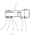
- the housing of the differential unit 1 has on its side face 3, intended for be attached to the circuit breaker 2, in the vicinity of its rear face 5 for attachment to the rail, five Keying pins 6,7,8,9,10. Among these five pawns, two 7.9 were buttoned or cut while the other three 6,8,10 extend perpendicular to said face lateral 3 on one side of the recess E intended to allow the fixing of the differential unit 1 on the rail.
- the case of the circuit breaker 2 comprises, in locations corresponding to those of pawns 6 to 10 when the differential block 1 is associated with the circuit breaker 2, ports 11 to 15.
- the first pin 6 associated with its orifice 11 achieves the coding industry standard.
- Pawn 10 performs the polarization by number of poles and makes it possible to verify that the two devices are of the three-pole type.
- Pawn 8 performs the coding by caliber, i.e. allows association only when the caliber of devices is less than 63A for the circuit breaker.
- the differential block also has five pawns, but these are the first 6 third 8 and fourth 9 remaining pawns, the others having been retracted, said 6,8,9 pawns corresponding respectively to the industrial standard, to a caliber less than 63A and the four-pole nature of the device. Note that we can add at will other pawns if it is necessary to take into account other characteristics.
- the differential block 1 comprises six slots for a pin 16 to 21.
- the first sends a coding relating to the industrial standard, the second bipolar character, the 3 rd to the domestic standard, the 4th to gauge 63A, the 5th character to the pole and the pole 6th character.
- the device shown is a three-pole differential block, industry standard and 63A caliber. This is why the third 18, and fifth 20 pawns starting from the left have been cut or lashed up.
- the housings of the devices are equipped with a number of coding pins or respectively of orifices provided with shutters, made of material with a removable part of the housing.
- This piece is unique for all types of devices, which allows you to manage only one room. It is only at the end of assembly that the pawns corresponding to non-verified characteristics are deleted for devices fitted of these pins, in general the additional devices, and that the shutters of the orifices corresponding to the verified characteristics are removed, for other devices, by general basic devices.
- this device can be used to provide keying between others devices, for example between a differential switch and circuit breakers.
- the polarization will not be limited to the standard, the caliber and the number of poles but could be extended to other criteria.
- the invention makes it possible to condemn any bad association while offering a maximum industrial rationalization.
- This principle of coding by pawn and obturator allows you to undo a large number of combinations by adding additional pawns.
Landscapes
- Engineering & Computer Science (AREA)
- Power Engineering (AREA)
- Switch Cases, Indication, And Locking (AREA)
- Distribution Board (AREA)
- Operating, Guiding And Securing Of Roll- Type Closing Members (AREA)
- Driving Mechanisms And Operating Circuits Of Arc-Extinguishing High-Tension Switches (AREA)
- Electrical Discharge Machining, Electrochemical Machining, And Combined Machining (AREA)
- Emergency Protection Circuit Devices (AREA)
- Breakers (AREA)
Applications Claiming Priority (2)
| Application Number | Priority Date | Filing Date | Title |
|---|---|---|---|
| FR9716418 | 1997-12-18 | ||
| FR9716418A FR2773003B1 (fr) | 1997-12-18 | 1997-12-18 | Dispositif de detrompage pour appareils electriques, en particulier pour disjoncteurs et interrupteurs differentiels |
Publications (2)
| Publication Number | Publication Date |
|---|---|
| EP0926792A1 true EP0926792A1 (de) | 1999-06-30 |
| EP0926792B1 EP0926792B1 (de) | 2006-06-14 |
Family
ID=9515054
Family Applications (1)
| Application Number | Title | Priority Date | Filing Date |
|---|---|---|---|
| EP98410141A Expired - Lifetime EP0926792B1 (de) | 1997-12-18 | 1998-12-09 | Verschlüsselungsvorrichtung für elektrische Geräte, insbesondere für Schutzschalter und Differentialschutzschalter |
Country Status (6)
| Country | Link |
|---|---|
| EP (1) | EP0926792B1 (de) |
| CN (1) | CN1085396C (de) |
| AT (1) | ATE330349T1 (de) |
| DE (1) | DE69834897T2 (de) |
| ES (1) | ES2264191T3 (de) |
| FR (1) | FR2773003B1 (de) |
Cited By (4)
| Publication number | Priority date | Publication date | Assignee | Title |
|---|---|---|---|---|
| FR2892852A1 (fr) * | 2005-10-28 | 2007-05-04 | Hager Electro S A S Soc Par Ac | Systeme de detrompage pour l'association d'appareils electriques |
| CN102082045A (zh) * | 2009-11-30 | 2011-06-01 | 施耐德电器工业公司 | 电气辅助件和用于与该电气辅助件配合的开关装置 |
| CN104733251A (zh) * | 2012-12-31 | 2015-06-24 | 吴红平 | 通信协议转换器的安装较为便利的智能塑壳断路器 |
| CN104733250A (zh) * | 2012-12-31 | 2015-06-24 | 吴红平 | 安装便利的智能塑壳断路器 |
Families Citing this family (1)
| Publication number | Priority date | Publication date | Assignee | Title |
|---|---|---|---|---|
| US11565367B2 (en) * | 2020-07-09 | 2023-01-31 | Applied Materials, Inc. | Retaining ring |
Citations (2)
| Publication number | Priority date | Publication date | Assignee | Title |
|---|---|---|---|---|
| EP0626712A1 (de) * | 1993-05-26 | 1994-11-30 | Bticino S.P.A. | Kupplungsvorrichtung zwischen zwei modularen elektrischen Geräten |
| EP0717425A1 (de) * | 1994-12-13 | 1996-06-19 | Bticino S.P.A. | Differenzieller Schutzmodul mit Sicherheitskupplung zur Ankupplung an einen multipolärem Schaltblock |
-
1997
- 1997-12-18 FR FR9716418A patent/FR2773003B1/fr not_active Expired - Fee Related
-
1998
- 1998-12-09 ES ES98410141T patent/ES2264191T3/es not_active Expired - Lifetime
- 1998-12-09 AT AT98410141T patent/ATE330349T1/de active
- 1998-12-09 DE DE69834897T patent/DE69834897T2/de not_active Expired - Lifetime
- 1998-12-09 EP EP98410141A patent/EP0926792B1/de not_active Expired - Lifetime
- 1998-12-18 CN CN98111661.2A patent/CN1085396C/zh not_active Expired - Lifetime
Patent Citations (2)
| Publication number | Priority date | Publication date | Assignee | Title |
|---|---|---|---|---|
| EP0626712A1 (de) * | 1993-05-26 | 1994-11-30 | Bticino S.P.A. | Kupplungsvorrichtung zwischen zwei modularen elektrischen Geräten |
| EP0717425A1 (de) * | 1994-12-13 | 1996-06-19 | Bticino S.P.A. | Differenzieller Schutzmodul mit Sicherheitskupplung zur Ankupplung an einen multipolärem Schaltblock |
Cited By (7)
| Publication number | Priority date | Publication date | Assignee | Title |
|---|---|---|---|---|
| FR2892852A1 (fr) * | 2005-10-28 | 2007-05-04 | Hager Electro S A S Soc Par Ac | Systeme de detrompage pour l'association d'appareils electriques |
| CN102082045A (zh) * | 2009-11-30 | 2011-06-01 | 施耐德电器工业公司 | 电气辅助件和用于与该电气辅助件配合的开关装置 |
| EP2328166A1 (de) * | 2009-11-30 | 2011-06-01 | Schneider Electric Industries SAS | Hilfsschalter zum Anschluss an einen Leitungsschutzschalter mit Montagefehlerschutz und passender Leitungsschutzschalter |
| FR2953325A1 (fr) * | 2009-11-30 | 2011-06-03 | Schneider Electric Ind Sas | Auxiliaire electrique etant destine a etre relie a un dispositif de coupure et comportant des moyens de detrompage, dispositif de coupure destine a collaborer avec un tel auxiliaire |
| CN102082045B (zh) * | 2009-11-30 | 2015-02-18 | 施耐德电器工业公司 | 电气辅助件和用于与该电气辅助件配合的开关装置 |
| CN104733251A (zh) * | 2012-12-31 | 2015-06-24 | 吴红平 | 通信协议转换器的安装较为便利的智能塑壳断路器 |
| CN104733250A (zh) * | 2012-12-31 | 2015-06-24 | 吴红平 | 安装便利的智能塑壳断路器 |
Also Published As
| Publication number | Publication date |
|---|---|
| ES2264191T3 (es) | 2006-12-16 |
| DE69834897D1 (de) | 2006-07-27 |
| CN1085396C (zh) | 2002-05-22 |
| DE69834897T2 (de) | 2006-11-30 |
| FR2773003A1 (fr) | 1999-06-25 |
| FR2773003B1 (fr) | 2000-02-11 |
| ATE330349T1 (de) | 2006-07-15 |
| CN1228603A (zh) | 1999-09-15 |
| EP0926792B1 (de) | 2006-06-14 |
Similar Documents
| Publication | Publication Date | Title |
|---|---|---|
| EP0598811B2 (de) | Geschlechtloser elektrischer verbinder | |
| EP1376638B1 (de) | Elektromagnetischer Schutz und Steuereinheit | |
| EP0926792A1 (de) | Verschlüsselungsvorrichtung für elektrische Geräte, insbesondere für Schutzschalter und Differentialschutzschalter | |
| CA2348111A1 (fr) | Dispositif a contacts multiples pour les systemes de barres de bus de puissance | |
| EP0649158B1 (de) | Differentialschutzblock mit Kabeldurchgang | |
| FR2502406A1 (fr) | Element de bornier pour la connexion de plusieurs conducteurs electriques a l'aide de ressorts lamellaires | |
| EP1026782B1 (de) | Verbindungsblock für elektrische Geräte | |
| EP0004266A1 (de) | Halterzusammenbau für einen Sammelschienensatz | |
| FR2787933A1 (fr) | Bornier electrique pourvu d'un dispositif de protection des bornes de raccordement electrique et appareil pourvu d'un tel bornier | |
| EP2849295B1 (de) | Elektrische Verteilungsanordnung mit einem mehrpoligen Stromverteilungskamm. | |
| EP1107363B1 (de) | Monopolarer Modularerverteiler | |
| FR2645602A1 (fr) | Ensemble de valve pneumatique ou hydraulique | |
| FR2749108A1 (fr) | Connecteur pour l'etablissement d'une connexion transversale entre appareils electriques modulaires alignes | |
| FR3062513A1 (fr) | Dispositif de connexion electrique avec fonction de consignation integree | |
| FR2845530A1 (fr) | Appareil electrique destine a etre monte sur un chassis | |
| EP0478469A1 (de) | Nulleiter- und Erdanschlussklemmen in einem elektrischen Verteilerkasten | |
| FR2703845A1 (fr) | Socle de prise de courant. | |
| FR2999024A1 (fr) | Appareillage electrique et rehausse pour un tel appareillage electrique | |
| FR2699745A1 (fr) | Prise de courant femelle, à protection intégrée. | |
| EP0797271B1 (de) | Sockel für Stromsteckdose | |
| FR2726401A1 (fr) | Dispositif de raccordement electrique pour un accessoire amovible de vehicule automobile | |
| EP0926775B1 (de) | Gehäuse für elektrische Verbinder | |
| FR3010840A1 (fr) | Borne de raccordement electrique d'un appareil electrique alimente par un peigne et appareil comportant une telle borne | |
| EP0609135B1 (de) | Vorverdrahtete Anschlussklemmleiste | |
| EP0768728A1 (de) | Elektrische Anschlussleiste |
Legal Events
| Date | Code | Title | Description |
|---|---|---|---|
| PUAI | Public reference made under article 153(3) epc to a published international application that has entered the european phase |
Free format text: ORIGINAL CODE: 0009012 |
|
| AK | Designated contracting states |
Kind code of ref document: A1 Designated state(s): AT DE ES GB IT |
|
| AX | Request for extension of the european patent |
Free format text: AL;LT;LV;MK;RO;SI |
|
| RAP1 | Party data changed (applicant data changed or rights of an application transferred) |
Owner name: SCHNEIDER ELECTRIC INDUSTRIES SA |
|
| 17P | Request for examination filed |
Effective date: 19991115 |
|
| AKX | Designation fees paid |
Free format text: AT DE ES GB IT |
|
| RAP1 | Party data changed (applicant data changed or rights of an application transferred) |
Owner name: SCHNEIDER ELECTRIC INDUSTRIES SA |
|
| RAP1 | Party data changed (applicant data changed or rights of an application transferred) |
Owner name: SCHNEIDER ELECTRIC INDUSTRIES SAS |
|
| GRAP | Despatch of communication of intention to grant a patent |
Free format text: ORIGINAL CODE: EPIDOSNIGR1 |
|
| GRAS | Grant fee paid |
Free format text: ORIGINAL CODE: EPIDOSNIGR3 |
|
| GRAA | (expected) grant |
Free format text: ORIGINAL CODE: 0009210 |
|
| AK | Designated contracting states |
Kind code of ref document: B1 Designated state(s): AT DE ES GB IT |
|
| REG | Reference to a national code |
Ref country code: GB Ref legal event code: FG4D Free format text: NOT ENGLISH |
|
| REF | Corresponds to: |
Ref document number: 69834897 Country of ref document: DE Date of ref document: 20060727 Kind code of ref document: P |
|
| GBT | Gb: translation of ep patent filed (gb section 77(6)(a)/1977) |
Effective date: 20060929 |
|
| REG | Reference to a national code |
Ref country code: ES Ref legal event code: FG2A Ref document number: 2264191 Country of ref document: ES Kind code of ref document: T3 |
|
| PLBE | No opposition filed within time limit |
Free format text: ORIGINAL CODE: 0009261 |
|
| STAA | Information on the status of an ep patent application or granted ep patent |
Free format text: STATUS: NO OPPOSITION FILED WITHIN TIME LIMIT |
|
| 26N | No opposition filed |
Effective date: 20070315 |
|
| PGFP | Annual fee paid to national office [announced via postgrant information from national office to epo] |
Ref country code: AT Payment date: 20131126 Year of fee payment: 16 Ref country code: DE Payment date: 20131206 Year of fee payment: 16 |
|
| REG | Reference to a national code |
Ref country code: DE Ref legal event code: R119 Ref document number: 69834897 Country of ref document: DE |
|
| REG | Reference to a national code |
Ref country code: AT Ref legal event code: MM01 Ref document number: 330349 Country of ref document: AT Kind code of ref document: T Effective date: 20141209 |
|
| PG25 | Lapsed in a contracting state [announced via postgrant information from national office to epo] |
Ref country code: DE Free format text: LAPSE BECAUSE OF NON-PAYMENT OF DUE FEES Effective date: 20150701 |
|
| PG25 | Lapsed in a contracting state [announced via postgrant information from national office to epo] |
Ref country code: AT Free format text: LAPSE BECAUSE OF NON-PAYMENT OF DUE FEES Effective date: 20141209 |
|
| PGFP | Annual fee paid to national office [announced via postgrant information from national office to epo] |
Ref country code: GB Payment date: 20161207 Year of fee payment: 19 |
|
| PGFP | Annual fee paid to national office [announced via postgrant information from national office to epo] |
Ref country code: IT Payment date: 20161221 Year of fee payment: 19 Ref country code: ES Payment date: 20161111 Year of fee payment: 19 |
|
| GBPC | Gb: european patent ceased through non-payment of renewal fee |
Effective date: 20171209 |
|
| PG25 | Lapsed in a contracting state [announced via postgrant information from national office to epo] |
Ref country code: IT Free format text: LAPSE BECAUSE OF NON-PAYMENT OF DUE FEES Effective date: 20171209 |
|
| PG25 | Lapsed in a contracting state [announced via postgrant information from national office to epo] |
Ref country code: GB Free format text: LAPSE BECAUSE OF NON-PAYMENT OF DUE FEES Effective date: 20171209 |
|
| REG | Reference to a national code |
Ref country code: ES Ref legal event code: FD2A Effective date: 20190702 |
|
| PG25 | Lapsed in a contracting state [announced via postgrant information from national office to epo] |
Ref country code: ES Free format text: LAPSE BECAUSE OF NON-PAYMENT OF DUE FEES Effective date: 20171210 |