EP0927508B1 - Airbag-steuergerät - Google Patents
Airbag-steuergerät Download PDFInfo
- Publication number
- EP0927508B1 EP0927508B1 EP97935473A EP97935473A EP0927508B1 EP 0927508 B1 EP0927508 B1 EP 0927508B1 EP 97935473 A EP97935473 A EP 97935473A EP 97935473 A EP97935473 A EP 97935473A EP 0927508 B1 EP0927508 B1 EP 0927508B1
- Authority
- EP
- European Patent Office
- Prior art keywords
- housing
- control unit
- circuit board
- cover
- accordance
- Prior art date
- Legal status (The legal status is an assumption and is not a legal conclusion. Google has not performed a legal analysis and makes no representation as to the accuracy of the status listed.)
- Expired - Lifetime
Links
- 230000001133 acceleration Effects 0.000 claims description 8
- 230000013011 mating Effects 0.000 claims 1
- 238000011156 evaluation Methods 0.000 description 2
- 238000009434 installation Methods 0.000 description 2
- 238000000034 method Methods 0.000 description 2
- 230000005855 radiation Effects 0.000 description 2
- 238000003466 welding Methods 0.000 description 2
- 230000002411 adverse Effects 0.000 description 1
- 229910052782 aluminium Inorganic materials 0.000 description 1
- XAGFODPZIPBFFR-UHFFFAOYSA-N aluminium Chemical compound [Al] XAGFODPZIPBFFR-UHFFFAOYSA-N 0.000 description 1
- 238000011161 development Methods 0.000 description 1
- 230000018109 developmental process Effects 0.000 description 1
- 239000000463 material Substances 0.000 description 1
- 229910052751 metal Inorganic materials 0.000 description 1
- 239000002184 metal Substances 0.000 description 1
- 230000035945 sensitivity Effects 0.000 description 1
- 239000007787 solid Substances 0.000 description 1
Images


Classifications
-
- H—ELECTRICITY
- H05—ELECTRIC TECHNIQUES NOT OTHERWISE PROVIDED FOR
- H05K—PRINTED CIRCUITS; CASINGS OR CONSTRUCTIONAL DETAILS OF ELECTRIC APPARATUS; MANUFACTURE OF ASSEMBLAGES OF ELECTRICAL COMPONENTS
- H05K5/00—Casings, cabinets or drawers for electric apparatus
-
- H—ELECTRICITY
- H05—ELECTRIC TECHNIQUES NOT OTHERWISE PROVIDED FOR
- H05K—PRINTED CIRCUITS; CASINGS OR CONSTRUCTIONAL DETAILS OF ELECTRIC APPARATUS; MANUFACTURE OF ASSEMBLAGES OF ELECTRICAL COMPONENTS
- H05K5/00—Casings, cabinets or drawers for electric apparatus
- H05K5/0026—Casings, cabinets or drawers for electric apparatus provided with connectors and printed circuit boards [PCB], e.g. automotive electronic control units
- H05K5/0047—Casings, cabinets or drawers for electric apparatus provided with connectors and printed circuit boards [PCB], e.g. automotive electronic control units having a two-part housing enclosing a PCB
- H05K5/006—Casings, cabinets or drawers for electric apparatus provided with connectors and printed circuit boards [PCB], e.g. automotive electronic control units having a two-part housing enclosing a PCB characterized by features for holding the PCB within the housing
-
- B—PERFORMING OPERATIONS; TRANSPORTING
- B60—VEHICLES IN GENERAL
- B60R—VEHICLES, VEHICLE FITTINGS, OR VEHICLE PARTS, NOT OTHERWISE PROVIDED FOR
- B60R21/00—Arrangements or fittings on vehicles for protecting or preventing injuries to occupants or pedestrians in case of accidents or other traffic risks
- B60R21/01—Electrical circuits for triggering passive safety arrangements, e.g. airbags, safety belt tighteners, in case of vehicle accidents or impending vehicle accidents
-
- H—ELECTRICITY
- H05—ELECTRIC TECHNIQUES NOT OTHERWISE PROVIDED FOR
- H05K—PRINTED CIRCUITS; CASINGS OR CONSTRUCTIONAL DETAILS OF ELECTRIC APPARATUS; MANUFACTURE OF ASSEMBLAGES OF ELECTRICAL COMPONENTS
- H05K5/00—Casings, cabinets or drawers for electric apparatus
- H05K5/0026—Casings, cabinets or drawers for electric apparatus provided with connectors and printed circuit boards [PCB], e.g. automotive electronic control units
- H05K5/0073—Casings, cabinets or drawers for electric apparatus provided with connectors and printed circuit boards [PCB], e.g. automotive electronic control units having specific features for mounting the housing on an external structure
-
- H—ELECTRICITY
- H05—ELECTRIC TECHNIQUES NOT OTHERWISE PROVIDED FOR
- H05K—PRINTED CIRCUITS; CASINGS OR CONSTRUCTIONAL DETAILS OF ELECTRIC APPARATUS; MANUFACTURE OF ASSEMBLAGES OF ELECTRICAL COMPONENTS
- H05K5/00—Casings, cabinets or drawers for electric apparatus
- H05K5/0026—Casings, cabinets or drawers for electric apparatus provided with connectors and printed circuit boards [PCB], e.g. automotive electronic control units
- H05K5/0078—Casings, cabinets or drawers for electric apparatus provided with connectors and printed circuit boards [PCB], e.g. automotive electronic control units specially adapted for acceleration sensors, e.g. crash sensors, airbag sensors
Definitions
- the invention relates to an airbag control device according to the preamble of claim 1; (see DE-A-4 111 883).
- Electronic control devices for personal protection devices in Motor vehicles such as airbags, belt tensioners, etc. include various electronic components on a circuit board, which are enclosed by a cover-provided housing, such as is described for example in DE 44 06 499 C2.
- the housing cover has the housing cover fastened to the motor vehicle Fastening tabs or flanges on which also the orientation of the control unit is determined. This Fixed orientation of the control unit is imperative, since it is usually used acceleration sensor a predetermined Direction of sensitivity.
- the circuit board is in the housing attached by screws. To get out of long lines Reducing the resulting radiation is mostly central Housing a screw attached as a diverting element.
- the invention has for its object a fastening for an airbag control unit that is simple, cost-effective assembly of the control unit allowed, whereby vibration problems occurring in the area of the circuit board are reduced to a minimum.
- the airbag control device according to the invention can be used of inexpensive parts, such as a die-cast housing and a lid made by deep drawing, quickly and with few fastening parts on the vehicle body be attached. Installation is also inexpensive. This is made possible by the fact that the invention only one central attachment point for the complete control unit is present, so only one fastening process instead of previously four screw connections, for example is. This means that at least two bolts and nuts, not only assembly time, but also material saved.
- control unit By eliminating the usual mounting tabs there is more space available for the control unit itself, whose internal volume can be increased.
- the circuit board area can be enlarged so that no two-sided PCB assembly or multi-layer arrangement required is.
- An airbag control unit 10 comprises a housing 20, for example an aluminum die-cast housing with a base 22, side walls 24 and a cover 26 made, for example, from deep-drawn sheet metal.
- the housing contains a printed circuit board 40 on which an evaluation circuit with various components 42 and one with the Evaluation circuit connected acceleration sensor 44 are arranged.
- a connector 46 serves as an interface and connection to the airbag and other control devices in the motor vehicle.
- the housing 20 has a central feedthrough 30, the housing base 22 being drawn inwards into the housing 20 and extending with molded parts through the housing to the other outside.
- the housing base 22 is in the middle of the housing bent inward so that it is a blind hole with a blind hole bottom 32 forms with a central opening 34.
- the blind hole floor 32 is located approximately at the height of the circuit board 40 and has a gradation to the end on the inside of the housing of the housing bottom 22. Due to the gradation is a support shoulder 70 formed, whose function is still discussed becomes.
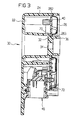
- the blind hole bottom 32 is one on the cover side Cylinder ring 36 pulled up over the cover 26 and the The height of the side wall 24 protrudes, as can be seen from FIG. 3 is.
- the cylinder ring 36 is forming a solid Segment section 38 formed with an asymmetrical interior, which will also be discussed later.
- the outside diameter the cylinder ring 36 is smaller than that Diameter of the outer circumference of the feedthrough 30 Blind hole wall.
- the cover 26 has a central opening 261 and is in the area down the opening 261 and part of the outer edges, i.e. towards the inside of the housing, forming support edges 262, 263 pulled. In the area of the corners are the Support edges widened to fastening tabs 264.
- the Cover 26 is shaped so that its inner support edge 263rd deeper than the outer support edge 262 and the mounting tabs 264 lies.
- the side wall 24 of the housing 20 is in the corner areas in Height of the circuit board 40 inwards to form support shoulders 72 drawn, which are shown in Figure 4. On these support shoulders 72 reach the cover 26 in the area the mounting tabs 264 for support.
- FIG. 2 illustrates the Assembly of cover 26, circuit board 40 and housing 20. Screw connections are used for this, i.e. these three parts will be assembled together using four screws 80, 82, 84, 86. Alternatively, only three screws can be used. For this purpose, the one additionally drawn in for illustration is used Screw 88 instead of screws 80 and 86. At the screwing process is described by the lid shape and the centrally provided support shoulder 70 the circuit board 40 clamped in the middle. This eliminates the one hand Screws or other fasteners for the circuit board and on the other hand there are vibrations of the circuit board prevented. By mounting the acceleration sensor 44 closer to a clamping point of the circuit board 40, ie in Near the edge, additional vibration protection can be added of the acceleration sensor can be created.
- the fastening and / or clamping the circuit board in the area of the central one Carrying out the housing or the cover provides an additional one Support point for the PCB, in the middle of the PCB, that with conventional control units by an additional Screw or similar had to be bought.
- the central one Clamping point fixes the circuit board in a central one Area that would otherwise show a strong tendency to vibrate would.
- the distances between which are decisive for the swing Fastening points are through the central clamping point kept low on all sides.
- the central clamping point enables also a ground connection from the circuit board to the housing 20 and the lid 26.
- Figure 5 illustrates a threaded weld stud 90 which welded to the schematically indicated body panel 100 and an asymmetrical head 92 with segment recess 94 and a shaft 96.
- the housing with the lid side on the shaft 96 of the welding stud 90 put on and is then due to the positive connection between the head 92 and the cylinder ring 36 then inevitably in the right orientation.
- the welding stud 90 has the task of the control unit 10 on Attach motor vehicle. It also serves as a diverting element for interference radiation.
Landscapes
- Engineering & Computer Science (AREA)
- Microelectronics & Electronic Packaging (AREA)
- Mechanical Engineering (AREA)
- Air Bags (AREA)
- Mounting Of Printed Circuit Boards And The Like (AREA)
- Automotive Seat Belt Assembly (AREA)
Description
- Figur 1:
- Eine perspektivische Draufsicht auf die Gehäusebodenseite eines Airbag-Steuergeräts,
- Figur 2:
- Eine perspektivische Ansicht auf die Deckelseite des Gehäuses,
- Figur 3:
- Eine Schnittansicht längs Linie B-B in Fig. 1,
- Figur 4:
- Eine Schnittansicht längs Linie A-A in Fig. 1 und
- Figur 5:
- Eine perspektivische Ansicht eines Gewindeschweißbolzens für die Montage des Gehäuses.
Ein Steckverbinder 46 dient als Schnittstelle und Anschluß zum Airbag und anderen Steuergeräten im Kraftfahrzeug. Das Gehäuse 20 weist eine zentrale Durchführung 30 auf, wobei der Gehäuseboden 22 nach innen in das Gehäuse 20 eingezogen ist und sich mit Anformteilen durch das Gehäuse hindurch bis zur anderen Außenseite erstreckt.
Claims (10)
- Airbag-Steuergerät, mit einer elektronische Bauteile (42) tragenden Leiterplatte (40), mit einem Gehäuse (20) für die Leiterplatte (40) und mit einem Deckel (26) für das Gehäuse (20), und mit Mitteln zur Befestigung des Steuergeräts an einem Kraftfahrzeug, wobei das Gehäuse (20) als Befestigungsmittel eine im wesentlichen zentrale Durchführung (30) aufweist, gegen die das Gehäuseinnere abgeschlossen ist, dadurch gekennzeichnet, daß sich die zentrale Durchführung (30) des Gehäuses (20) durch die Leiterplatte (40) und den Deckel (26) erstreckt.
- Airbag-Steuergerät nach Anspruch 1, dadurch gekennzeichnet, daß die zentrale Durchführung (30) des Gehäuses (20) zumindest bereichsweise eine asymmetrische Form aufweist, die bei Formschlußverbindung mit einem komplementär geformten Befestigungsteil (90) eine Lagefixierung bildet.
- Airbag-Steuergerät nach Anspruch 1, dadurch gekennzeichnet, daß die Leiterplatte (40) im Bereich der zentralen Durchführung (30) am Gehäuse (20) oder am Deckel (26) gehalten oder befestigt ist.
- Airbag-Steuergerät nach Anspruch 1, dadurch gekennzeichnet, daß im Bereich der zentralen Durchführung (30) des Gehäuses (20) eine Auflage (70) für die Leiterplatte (40) vorgesehen ist und der Deckel (26) so geformt ist, daß er die Leiterplatte (40) druckbeaufschlagt, womit eine zentrale Einspannung der Leiterplatte vorgesehen ist.
- Airbag-Steuergerät nach Anspruch 4, dadurch gekennzeichnet, daß der Deckel (26) im Bereich der zentralen Gehäusedurchführung (30) tiefer als die Außenränder ist.
- Airbag-Steuergerät nach Anspruch 5, dadurch gekennzeichnet, daß an der zentralen Einspannstelle (70) der Leiterplatte eine Masseanbindung an das Gehäuse (20) und den Deckel (26) vorgesehen ist.
- Airbag-Steuergerät nach Anspruch 3, dadurch gekennzeichnet, daß die Leiterplatte (40) an mindestens einer weiteren Stelle (80,82,84,86) am Gehäuse (20) oder am Deckel (26) gehalten wird.
- Airbag-Steuergerät nach Anspruch 7, dadurch gekennzeichnet, daß das Gehäuse (20), die Leiterplatte (40) und der Dekkel (26) gemeinsam miteinander verschraubt sind.
- Airbag-Steuergerät nach Anspruch 1, dadurch gekennzeichnet, daß die Leiterplatte einen Beschleunigungssensor trägt.
- Airbag-Steuergerät nach den Ansprüchen 3, 7 und 9, dadurch gekennzeichnet, daß der Beschleunigungssensor zwischen der zentralen Durchführung (30) und der weiteren Stelle (80,82,84,86) auf der Leiterplatte (40) angeordnet ist.
Applications Claiming Priority (3)
| Application Number | Priority Date | Filing Date | Title |
|---|---|---|---|
| DE19638454 | 1996-09-19 | ||
| DE19638454 | 1996-09-19 | ||
| PCT/DE1997/001561 WO1998012904A1 (de) | 1996-09-19 | 1997-07-23 | Airbag-steuergerät |
Publications (2)
| Publication Number | Publication Date |
|---|---|
| EP0927508A1 EP0927508A1 (de) | 1999-07-07 |
| EP0927508B1 true EP0927508B1 (de) | 2000-06-14 |
Family
ID=7806256
Family Applications (1)
| Application Number | Title | Priority Date | Filing Date |
|---|---|---|---|
| EP97935473A Expired - Lifetime EP0927508B1 (de) | 1996-09-19 | 1997-07-23 | Airbag-steuergerät |
Country Status (6)
| Country | Link |
|---|---|
| US (1) | US6213495B1 (de) |
| EP (1) | EP0927508B1 (de) |
| JP (1) | JP3370682B2 (de) |
| KR (1) | KR100296235B1 (de) |
| DE (1) | DE59701895D1 (de) |
| WO (1) | WO1998012904A1 (de) |
Cited By (3)
| Publication number | Priority date | Publication date | Assignee | Title |
|---|---|---|---|---|
| DE102008002160A1 (de) | 2008-06-02 | 2009-12-03 | Robert Bosch Gmbh | Steuergerät für Personenschutzmittel für ein Fahrzeug und Verfahren zum Zusammenbau eines Steuergeräts für Personenschutzmittel für ein Fahrzeug |
| DE102008040156A1 (de) | 2008-07-03 | 2010-01-07 | Robert Bosch Gmbh | Steuergerät für Personenschutzmittel für ein Fahrzeug und ein Verfahren zum Zusammenbau eines solchen Steuergeräts |
| DE102008040157A1 (de) | 2008-07-03 | 2010-01-07 | Robert Bosch Gmbh | Steuergerät für Personenschutzmittel für ein Fahrzeug bzw. Verfahren zum Zusammenbau eines solchen Steuergeräts |
Families Citing this family (19)
| Publication number | Priority date | Publication date | Assignee | Title |
|---|---|---|---|---|
| DE19837833A1 (de) * | 1998-08-20 | 2000-02-10 | Daimler Chrysler Ag | Elektronisches Gerät |
| DE19841258C1 (de) * | 1998-09-09 | 2000-03-16 | Siemens Ag | Steuergerät |
| EP1050202B1 (de) | 1998-11-24 | 2005-06-22 | Continental Teves AG & Co. oHG | Anordnung zum schutz von elektronischen funktionseinheiten und/oder funktionsgruppen |
| DE19911989C2 (de) * | 1999-03-17 | 2003-04-24 | Trw Automotive Electron & Comp | Metallgehäuse |
| DE19911990A1 (de) * | 1999-03-17 | 2000-09-28 | Trw Automotive Electron & Comp | Metallgehäuse, insbesondere für ein Airbag-Steuergerät |
| DE29918914U1 (de) * | 1999-10-27 | 2000-03-09 | TRW Automotive Electronics & Components GmbH & Co. KG, 78315 Radolfzell | Steuergerät für Insassen-Rückhaltesysteme in Fahrzeugen |
| DE20019524U1 (de) * | 2000-11-17 | 2001-03-29 | TRW Automotive Electronics & Components GmbH & Co. KG, 78315 Radolfzell | Gehäusesystem für sicherheitsrelevante Steuergeräte in Kraftfahrzeugen |
| US6913472B2 (en) | 2002-06-28 | 2005-07-05 | Siemens Vdo Automotive Corporation | Method and apparatus for attaching a sensor assembly in a control unit |
| DE10238528A1 (de) * | 2002-08-22 | 2004-03-04 | Robert Bosch Gmbh | Befestigungsanordnung |
| US20060288464A1 (en) * | 2005-06-24 | 2006-12-28 | Warden Matthew P | Personal protection device |
| DE102009045565A1 (de) * | 2009-10-12 | 2011-04-14 | Robert Bosch Gmbh | Adapterplatte zur Befestigung eines Gehäuses in einem Fahrzeug und korrespondierendes Steuergerät |
| JP5629384B2 (ja) * | 2011-09-22 | 2014-11-19 | オートリブ ディベロップメント エービー | エアバッグ展開用電子回路装置 |
| ITTO20111168A1 (it) * | 2011-12-19 | 2013-06-20 | Gate Srl | Unita' elettronica, in particolare unita' di controllo per il motore di un elettroventilatore |
| JP6257881B2 (ja) * | 2012-05-31 | 2018-01-10 | 株式会社ミクニ | エンジンコントロールユニット |
| JP5747894B2 (ja) * | 2012-11-01 | 2015-07-15 | 株式会社デンソー | 電子装置用ケース |
| CN105453712B (zh) * | 2013-08-13 | 2017-03-29 | 三菱电机株式会社 | 电子设备 |
| US10788509B2 (en) * | 2017-06-09 | 2020-09-29 | Simmonds Precision Products, Inc. | High frequency accelerometer housing including circuit board disposed directly above support pad |
| CN114497942B (zh) * | 2021-12-06 | 2023-07-25 | 深圳市鸿富胜科技有限公司 | 一种通讯基站用合路器 |
| DE102023132202A1 (de) | 2023-11-20 | 2025-05-22 | Leoni Bordnetz-Systeme Gmbh | Befestigung von Steuergeräten |
Family Cites Families (17)
| Publication number | Priority date | Publication date | Assignee | Title |
|---|---|---|---|---|
| JPS5111172Y2 (de) * | 1971-05-10 | 1976-03-25 | ||
| US3774938A (en) * | 1972-09-25 | 1973-11-27 | Gen Motors Corp | Velocity responsive sensor for vehicle occupant restraints |
| JPS5331161Y2 (de) * | 1973-08-17 | 1978-08-03 | ||
| DE2813457A1 (de) * | 1978-03-29 | 1979-10-11 | Bosch Gmbh Robert | Einrichtung zur ausloesung von rueckhaltesystemen fuer kraftfahrzeuginsassen |
| DE8215422U1 (de) * | 1982-05-27 | 1982-09-23 | Robert Bosch Gmbh, 7000 Stuttgart | Elektronisches Steuergerät, insbesondere für Kraftfahrzeuge |
| DE3319724A1 (de) * | 1983-05-31 | 1984-12-06 | Özgürgil, Murat, 8028 Taufkirchen | Koch-, back/brat- und grillgeraet mit grillvorrichtung (kompaktgeraet) mit austauschbaren kohle-, gas- und elektroheizquellevorrichtung fuer camping, haushalt und gastronomie |
| DE3570956D1 (en) * | 1985-03-23 | 1989-07-13 | Petri Ag | Steering wheel with a current conduction to a shock-preventing airbag-safety system situated in a steering-wheel bowl |
| US4811168A (en) * | 1987-11-23 | 1989-03-07 | Chesnut Milton L | Housing and connector apparatus for electronic circuit |
| JPH03253440A (ja) * | 1990-03-01 | 1991-11-12 | Zexel Corp | 車両安全装置のための制御システム |
| GB2242871B (en) * | 1990-04-12 | 1994-05-04 | Autoliv Dev | Improvements in or relating to an air-bag arrangement |
| JPH04342638A (ja) * | 1991-05-17 | 1992-11-30 | Nippon Oil & Fats Co Ltd | エアバッグ装置 |
| US5327796A (en) * | 1992-12-28 | 1994-07-12 | General Motors Corporation | Horn switch actuated by rocking air bag module |
| DE4406499C2 (de) | 1994-02-28 | 1996-02-08 | Siemens Ag | Sensoreinheit zum Steuern eines Insassenschutzsystems eines Kraftfahrzeugs |
| FR2728847B1 (fr) * | 1994-12-28 | 1997-01-31 | Sagem Autoliv | Calculateur de sac a air (air bag) de vehicule |
| US5590900A (en) * | 1995-07-21 | 1997-01-07 | Avibank Mfg., Inc. | Air bag mounting system |
| US5873597A (en) * | 1996-02-07 | 1999-02-23 | Robert Bosch Corporation | Modular sensor unit console |
| DE19622228C1 (de) * | 1996-06-03 | 1997-06-26 | Kostal Leopold Gmbh & Co Kg | Einrichtung für Kraftfahrzeuge |
-
1997
- 1997-07-23 WO PCT/DE1997/001561 patent/WO1998012904A1/de not_active Ceased
- 1997-07-23 JP JP51413298A patent/JP3370682B2/ja not_active Expired - Fee Related
- 1997-07-23 EP EP97935473A patent/EP0927508B1/de not_active Expired - Lifetime
- 1997-07-23 DE DE59701895T patent/DE59701895D1/de not_active Expired - Fee Related
-
1999
- 1999-03-17 KR KR1019997002255A patent/KR100296235B1/ko not_active Expired - Fee Related
- 1999-03-19 US US09/272,963 patent/US6213495B1/en not_active Expired - Fee Related
Cited By (4)
| Publication number | Priority date | Publication date | Assignee | Title |
|---|---|---|---|---|
| DE102008002160A1 (de) | 2008-06-02 | 2009-12-03 | Robert Bosch Gmbh | Steuergerät für Personenschutzmittel für ein Fahrzeug und Verfahren zum Zusammenbau eines Steuergeräts für Personenschutzmittel für ein Fahrzeug |
| DE102008040156A1 (de) | 2008-07-03 | 2010-01-07 | Robert Bosch Gmbh | Steuergerät für Personenschutzmittel für ein Fahrzeug und ein Verfahren zum Zusammenbau eines solchen Steuergeräts |
| WO2010000523A1 (de) * | 2008-07-03 | 2010-01-07 | Robert Bosch Gmbh | Steuergerät für personenschutzmittel für ein fahrzeug und ein verfahren zum zusammenbau eines solchen steuergeräts |
| DE102008040157A1 (de) | 2008-07-03 | 2010-01-07 | Robert Bosch Gmbh | Steuergerät für Personenschutzmittel für ein Fahrzeug bzw. Verfahren zum Zusammenbau eines solchen Steuergeräts |
Also Published As
| Publication number | Publication date |
|---|---|
| KR100296235B1 (ko) | 2001-08-07 |
| EP0927508A1 (de) | 1999-07-07 |
| JP3370682B2 (ja) | 2003-01-27 |
| DE59701895D1 (de) | 2000-07-20 |
| WO1998012904A1 (de) | 1998-03-26 |
| US6213495B1 (en) | 2001-04-10 |
| JP2000502639A (ja) | 2000-03-07 |
| KR20000036200A (ko) | 2000-06-26 |
Similar Documents
| Publication | Publication Date | Title |
|---|---|---|
| EP0927508B1 (de) | Airbag-steuergerät | |
| DE10104568B4 (de) | Montageaufbau einer gedruckten Schalttafel für eine elektronische Steuereinheit | |
| DE4121263C2 (de) | Halterung für eine Hilfseinrichtung an einem Motor, insbesondere Kraftfahrzeugmotor | |
| DE19530941B4 (de) | Fahrzeugtür mit einem zur Halterung eines Außenspiegels vorgesehenen Spiegeldreieck | |
| DE102006026247A1 (de) | Ultraschallsensorvorrichtung und Ultraschallwandler | |
| DE4134673C1 (de) | ||
| DE202007013477U1 (de) | Fahrer-Alarmsystem für das Lenkrad eines Motorfahrzeugs | |
| DE102015206482A1 (de) | Steuergerät | |
| EP3931539B1 (de) | Drehmomentsensoreinheit mit einer magnetischen abschirmung | |
| EP0193862B1 (de) | Fahrzeug mit einem Aussenspiegel | |
| DE102004001098A1 (de) | Piezoelektrisches Material zum Dämpfen von Vibrationen eines Armaturenbretts und/oder einer Lenksäule | |
| EP0348618B1 (de) | Haltevorrichtung | |
| DE19845777A1 (de) | Befestigungsvorrichtung für Airbags von Kraftfahrzeugen | |
| DE3323624A1 (de) | Gehaeuse fuer schwingungs- und stossempfindliche geraete | |
| DE102004043888B4 (de) | Beschleunigungssensoreinheit | |
| EP0312740A1 (de) | Druckwandler mit einer Schaltungsplatine, insbesondere zur Steuerung eines Kraftfahrzeugs | |
| DE3013684C2 (de) | Klopfsensor | |
| DE102008037278A1 (de) | Elektronisches Steuergerät, insbesondere zur Steuerung eines Sicherheitssystems und/oder Komfortsystems, in einem Kraftfahrzeug | |
| DE102009023317A1 (de) | Elektronisches Steuergerät, insbesondere zur Steuerung eines Sicherheitssystems und/oder Komfortsystems, in einem Kraftfahrzeug | |
| DE102018105501B4 (de) | Abschirmvorrichtung für eine Ultraschallsensorvorrichtung und Verfahren zur Herstellung einer Ultraschallsensorvorrichtung | |
| EP0803409B1 (de) | Beifahrer-Airbag-Modul | |
| DE4005090C2 (de) | ||
| EP0528104B1 (de) | Gehäuseverschlussdeckel | |
| EP1949041B1 (de) | Beschleunigungssensor | |
| DE602004011103T2 (de) | Motorlagervorrichtung |
Legal Events
| Date | Code | Title | Description |
|---|---|---|---|
| PUAI | Public reference made under article 153(3) epc to a published international application that has entered the european phase |
Free format text: ORIGINAL CODE: 0009012 |
|
| 17P | Request for examination filed |
Effective date: 19990304 |
|
| AK | Designated contracting states |
Kind code of ref document: A1 Designated state(s): DE FR GB IT |
|
| GRAG | Despatch of communication of intention to grant |
Free format text: ORIGINAL CODE: EPIDOS AGRA |
|
| 17Q | First examination report despatched |
Effective date: 19991102 |
|
| GRAG | Despatch of communication of intention to grant |
Free format text: ORIGINAL CODE: EPIDOS AGRA |
|
| GRAH | Despatch of communication of intention to grant a patent |
Free format text: ORIGINAL CODE: EPIDOS IGRA |
|
| GRAH | Despatch of communication of intention to grant a patent |
Free format text: ORIGINAL CODE: EPIDOS IGRA |
|
| GRAA | (expected) grant |
Free format text: ORIGINAL CODE: 0009210 |
|
| AK | Designated contracting states |
Kind code of ref document: B1 Designated state(s): DE FR GB IT |
|
| REF | Corresponds to: |
Ref document number: 59701895 Country of ref document: DE Date of ref document: 20000720 |
|
| GBT | Gb: translation of ep patent filed (gb section 77(6)(a)/1977) |
Effective date: 20000710 |
|
| ITF | It: translation for a ep patent filed | ||
| ET | Fr: translation filed | ||
| PLBE | No opposition filed within time limit |
Free format text: ORIGINAL CODE: 0009261 |
|
| STAA | Information on the status of an ep patent application or granted ep patent |
Free format text: STATUS: NO OPPOSITION FILED WITHIN TIME LIMIT |
|
| 26N | No opposition filed | ||
| REG | Reference to a national code |
Ref country code: GB Ref legal event code: IF02 |
|
| PGFP | Annual fee paid to national office [announced via postgrant information from national office to epo] |
Ref country code: FR Payment date: 20090716 Year of fee payment: 13 |
|
| PGFP | Annual fee paid to national office [announced via postgrant information from national office to epo] |
Ref country code: GB Payment date: 20090720 Year of fee payment: 13 Ref country code: DE Payment date: 20090731 Year of fee payment: 13 |
|
| PGFP | Annual fee paid to national office [announced via postgrant information from national office to epo] |
Ref country code: IT Payment date: 20090725 Year of fee payment: 13 |
|
| GBPC | Gb: european patent ceased through non-payment of renewal fee |
Effective date: 20100723 |
|
| REG | Reference to a national code |
Ref country code: FR Ref legal event code: ST Effective date: 20110331 |
|
| PG25 | Lapsed in a contracting state [announced via postgrant information from national office to epo] |
Ref country code: DE Free format text: LAPSE BECAUSE OF NON-PAYMENT OF DUE FEES Effective date: 20110201 |
|
| REG | Reference to a national code |
Ref country code: DE Ref legal event code: R119 Ref document number: 59701895 Country of ref document: DE Effective date: 20110201 |
|
| PG25 | Lapsed in a contracting state [announced via postgrant information from national office to epo] |
Ref country code: IT Free format text: LAPSE BECAUSE OF NON-PAYMENT OF DUE FEES Effective date: 20100723 Ref country code: FR Free format text: LAPSE BECAUSE OF NON-PAYMENT OF DUE FEES Effective date: 20100802 |
|
| PG25 | Lapsed in a contracting state [announced via postgrant information from national office to epo] |
Ref country code: GB Free format text: LAPSE BECAUSE OF NON-PAYMENT OF DUE FEES Effective date: 20100723 |