EP0927687A2 - Method and means for transfer of granular materials - Google Patents
Method and means for transfer of granular materials Download PDFInfo
- Publication number
- EP0927687A2 EP0927687A2 EP98124583A EP98124583A EP0927687A2 EP 0927687 A2 EP0927687 A2 EP 0927687A2 EP 98124583 A EP98124583 A EP 98124583A EP 98124583 A EP98124583 A EP 98124583A EP 0927687 A2 EP0927687 A2 EP 0927687A2
- Authority
- EP
- European Patent Office
- Prior art keywords
- granular material
- screen
- transfer means
- layer
- belt
- Prior art date
- Legal status (The legal status is an assumption and is not a legal conclusion. Google has not performed a legal analysis and makes no representation as to the accuracy of the status listed.)
- Granted
Links
- 239000008187 granular material Substances 0.000 title claims abstract description 96
- 238000012546 transfer Methods 0.000 title claims abstract description 53
- 238000000034 method Methods 0.000 title claims abstract description 28
- 239000000843 powder Substances 0.000 claims abstract description 53
- 239000012530 fluid Substances 0.000 claims abstract description 27
- 238000003825 pressing Methods 0.000 claims abstract description 25
- 239000000919 ceramic Substances 0.000 claims abstract description 11
- 238000011144 upstream manufacturing Methods 0.000 claims abstract description 4
- 230000009471 action Effects 0.000 claims description 4
- 238000011049 filling Methods 0.000 claims description 4
- 238000007664 blowing Methods 0.000 claims 1
- 229910010293 ceramic material Inorganic materials 0.000 claims 1
- 239000010410 layer Substances 0.000 description 71
- 239000000463 material Substances 0.000 description 27
- 238000002156 mixing Methods 0.000 description 15
- 238000004144 decalcomania Methods 0.000 description 13
- 238000011068 loading method Methods 0.000 description 11
- 238000005034 decoration Methods 0.000 description 9
- 230000000694 effects Effects 0.000 description 8
- 230000035699 permeability Effects 0.000 description 8
- 239000002245 particle Substances 0.000 description 7
- 230000008859 change Effects 0.000 description 6
- 238000005516 engineering process Methods 0.000 description 6
- 238000013519 translation Methods 0.000 description 6
- 230000001464 adherent effect Effects 0.000 description 5
- 238000004519 manufacturing process Methods 0.000 description 4
- 230000002093 peripheral effect Effects 0.000 description 4
- 230000008901 benefit Effects 0.000 description 3
- 238000003780 insertion Methods 0.000 description 3
- 230000037431 insertion Effects 0.000 description 3
- 239000002344 surface layer Substances 0.000 description 3
- 230000004888 barrier function Effects 0.000 description 2
- 238000004140 cleaning Methods 0.000 description 2
- 238000006073 displacement reaction Methods 0.000 description 2
- 230000005484 gravity Effects 0.000 description 2
- 239000000203 mixture Substances 0.000 description 2
- 230000036961 partial effect Effects 0.000 description 2
- 230000035515 penetration Effects 0.000 description 2
- 230000003068 static effect Effects 0.000 description 2
- 238000013517 stratification Methods 0.000 description 2
- 230000035508 accumulation Effects 0.000 description 1
- 238000009825 accumulation Methods 0.000 description 1
- -1 as already explained Substances 0.000 description 1
- 239000003795 chemical substances by application Substances 0.000 description 1
- 239000011248 coating agent Substances 0.000 description 1
- 238000000576 coating method Methods 0.000 description 1
- 238000000354 decomposition reaction Methods 0.000 description 1
- 238000007599 discharging Methods 0.000 description 1
- 238000009826 distribution Methods 0.000 description 1
- 238000000605 extraction Methods 0.000 description 1
- 230000009969 flowable effect Effects 0.000 description 1
- 238000001033 granulometry Methods 0.000 description 1
- 238000009434 installation Methods 0.000 description 1
- 230000002452 interceptive effect Effects 0.000 description 1
- 230000000670 limiting effect Effects 0.000 description 1
- 239000007788 liquid Substances 0.000 description 1
- 239000002184 metal Substances 0.000 description 1
- 238000012986 modification Methods 0.000 description 1
- 230000004048 modification Effects 0.000 description 1
- 230000000149 penetrating effect Effects 0.000 description 1
- 238000005498 polishing Methods 0.000 description 1
- 229910052573 porcelain Inorganic materials 0.000 description 1
- 238000004064 recycling Methods 0.000 description 1
- 230000002829 reductive effect Effects 0.000 description 1
- 230000001105 regulatory effect Effects 0.000 description 1
- 238000007790 scraping Methods 0.000 description 1
- 238000007789 sealing Methods 0.000 description 1
- 238000000926 separation method Methods 0.000 description 1
- 125000006850 spacer group Chemical group 0.000 description 1
- 239000000126 substance Substances 0.000 description 1
- 238000006467 substitution reaction Methods 0.000 description 1
- 230000001360 synchronised effect Effects 0.000 description 1
- 238000009966 trimming Methods 0.000 description 1
Images


Classifications
-
- B—PERFORMING OPERATIONS; TRANSPORTING
- B28—WORKING CEMENT, CLAY, OR STONE
- B28B—SHAPING CLAY OR OTHER CERAMIC COMPOSITIONS; SHAPING SLAG; SHAPING MIXTURES CONTAINING CEMENTITIOUS MATERIAL, e.g. PLASTER
- B28B13/00—Feeding the unshaped material to moulds or apparatus for producing shaped articles; Discharging shaped articles from such moulds or apparatus
- B28B13/02—Feeding the unshaped material to moulds or apparatus for producing shaped articles
- B28B13/0215—Feeding the moulding material in measured quantities from a container or silo
- B28B13/022—Feeding several successive layers, optionally of different materials
-
- B—PERFORMING OPERATIONS; TRANSPORTING
- B28—WORKING CEMENT, CLAY, OR STONE
- B28B—SHAPING CLAY OR OTHER CERAMIC COMPOSITIONS; SHAPING SLAG; SHAPING MIXTURES CONTAINING CEMENTITIOUS MATERIAL, e.g. PLASTER
- B28B1/00—Producing shaped prefabricated articles from the material
- B28B1/005—Devices or processes for obtaining articles having a marble appearance
-
- B—PERFORMING OPERATIONS; TRANSPORTING
- B28—WORKING CEMENT, CLAY, OR STONE
- B28B—SHAPING CLAY OR OTHER CERAMIC COMPOSITIONS; SHAPING SLAG; SHAPING MIXTURES CONTAINING CEMENTITIOUS MATERIAL, e.g. PLASTER
- B28B13/00—Feeding the unshaped material to moulds or apparatus for producing shaped articles; Discharging shaped articles from such moulds or apparatus
- B28B13/02—Feeding the unshaped material to moulds or apparatus for producing shaped articles
- B28B13/0205—Feeding the unshaped material to moulds or apparatus for producing shaped articles supplied to the moulding device in form of a coherent mass of material, e.g. a lump or an already partially preshaped tablet, pastil or the like
-
- B—PERFORMING OPERATIONS; TRANSPORTING
- B28—WORKING CEMENT, CLAY, OR STONE
- B28B—SHAPING CLAY OR OTHER CERAMIC COMPOSITIONS; SHAPING SLAG; SHAPING MIXTURES CONTAINING CEMENTITIOUS MATERIAL, e.g. PLASTER
- B28B13/00—Feeding the unshaped material to moulds or apparatus for producing shaped articles; Discharging shaped articles from such moulds or apparatus
- B28B13/02—Feeding the unshaped material to moulds or apparatus for producing shaped articles
- B28B13/0215—Feeding the moulding material in measured quantities from a container or silo
-
- B—PERFORMING OPERATIONS; TRANSPORTING
- B28—WORKING CEMENT, CLAY, OR STONE
- B28B—SHAPING CLAY OR OTHER CERAMIC COMPOSITIONS; SHAPING SLAG; SHAPING MIXTURES CONTAINING CEMENTITIOUS MATERIAL, e.g. PLASTER
- B28B13/00—Feeding the unshaped material to moulds or apparatus for producing shaped articles; Discharging shaped articles from such moulds or apparatus
- B28B13/02—Feeding the unshaped material to moulds or apparatus for producing shaped articles
- B28B13/0295—Treating the surface of the fed layer, e.g. removing material or equalization of the surface
-
- B—PERFORMING OPERATIONS; TRANSPORTING
- B28—WORKING CEMENT, CLAY, OR STONE
- B28B—SHAPING CLAY OR OTHER CERAMIC COMPOSITIONS; SHAPING SLAG; SHAPING MIXTURES CONTAINING CEMENTITIOUS MATERIAL, e.g. PLASTER
- B28B3/00—Producing shaped articles from the material by using presses; Presses specially adapted therefor
Definitions
- the invention relates to a method and relative apparatus for transferring in a controlled manner granular material on a support; in particular, the invention can be applied to the manufacturing of ceramic tiles to add on or take from them granular material.
- granular material means a loose product capable of flowing, constituted by powders, granules of any form and dimension, scales, small tesserae or any mixture of said pieces.
- IT-B-1268908 discloses a system for decorating objects with a powdery decorating product, in which the decorating product is made to pass through the meshes of a silk-screen and is deposited on predetermined areas of a surface to be decorated.
- PCT/EP94/04291 discloses a system in which a decorating product, in a powdery state, is incorporated in shaped cavities of a transport belt and is projected from the belt onto a surface to be decorated.
- These systems provide for the decorating product being incorporated in a suitable transfer means, i.e. a silk-screen or a belt, and then ejected from said transfer means; so wear of the silk-screen and changes in the granulometry of the decorating product have been found due to the sliding of the product on the transfer means; furthermore these systems are not suitable for treating granules having large dimensions.
- a purpose of the present invention is to improve the known decorating machines, particularly to make possible to reduce the strengths on the particles of decorating product, to change and control the thickness of decorating product to be applied, and to reduce wear of the silk-screens and/or the dies used, all that causing variability of the results.
- An other purpose of the present invention is to make possible to decorate a support even with rough granular materials, preserving a good definition and without the need to recover the material distributed in excess.
- a further purpose of the present invention is to make possible to change the thickness of a granular material layer in an easy and controllable way in order to obtain decorating effects on it.
- a first technique described in IT-B-890769 was to use multiple loading carriages, but, said technique did not allow to obtain the required aesthetic effects and, in addition, extended substantially the pressing cycles.
- IT-B-1146358 discloses a rotating die multiple mould press; in this case, even if there is the possibility of obtaining fair aesthetic results, remarkable financial commitments are required, special presses being required to be used. Furthermore the moulds are very bulky, expensive, complicated and it is almost impossible to use multiple parallel imprints.
- This method allows to have a good definition of the decoration but involves a considerable increase of the costs because, first of all, the insertion of the decalcomania into the mould has to be done before or after the insertion of the powder constituting the tile body; more operations are therefore needed to load the mould which increase greatly the duration of the working cycle.
- a decorating layer for example a decalcomania
- An other object of the present invention is to allow said decalcomania to be obtained directly during the production cycle related to the pressing.
- a further object of the present invention is to obtain an apparatus, which may be applied to the more widely used presses for forming ceramic tiles, i.e. presses having moulds with lower die, side die and punch always in axis, said apparatus allowing, during a production cycle with single pressing, a filling of the mould space without relative displacements among the granules, i.e. allowing different granular materials to be introduced into the mould in a single filling operation, even according to patterns well defined in the stratification and at the surface, without the presence of excess of powder to be recycled and without loss of productivity.
- a further purpose of the present invention is to improve the described technology in order to overcome its drawbacks, first of all, to allow a mould to be loaded in only one loading operation, with a well defined and controlled stratigraphical and plan arrangement of different powders and then with the possibility of mutually mixing along a vertical direction the different layers of powder in a controlled and selective way, i.e. just only in a portion of the thickness or in a selected portion of the plan surface.
- transfer means of granular material including a permeable baffle through which a fluid acts on said granular material.
- a method for transferring granular material comprising acting with a fluid on a granular material through a permeable baffle.
- transfer means for transferring granular material to a pressing station for ceramic tiles comprising a thin belt where said granular material lays, said thin belt being wound off a spool arranged upstream the pressing station and rewound on a spool downstream the said pressing station.
- a method for preparing a layer of powders designed to be pressed in form of ceramic tile characterised in that it comprises the following steps:
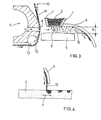
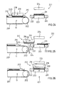
- Ejecting means 7 are provided at a side of the gap 6, said ejecting means having an ejecting nozzle 8 capable of directing a stream of a transporting fluid, for examples compressed air, towards the gap 6 in such a way as to force the product 2 which is in the gap 6 to be discharged at the opposite side, where a downwardly-bent deflecting baffle 9 directs the product towards the support 4.
- a transporting fluid for examples compressed air
- the ejecting nozzle 8 is provided with an end turned towards the gap 6 on which end a selective screen 10 is caused to pass.
- the screen 10 is provided with barrier regions 11, that is regions through which the transport fluid can not pass, and regions 12 permeable to the transport fluid, through which the transport fluid can easily pass and act on the product 2, which is in the gap 6, in order to transport it.
- the screen 10 is flexible, so that it can be wound on roller means 13, supported in a free to rotate manner below the ejecting means 7, and on a motorised roller 14, arranged above the ejecting means 7.
- the screen 10, for example, can consists of a usual silk-screen with any pattern defined by the permeable regions 12.
- the transport fluid ejected by the ejecting nozzle 8 moves from the gap 6 mainly the product 2 facing the permeable regions 12, so defining a corresponding decoration on the support 4.
- the support 4 can be yielding, for example consisting of powders defining a soft layer: in this case the product 2 can hit the upper surface of the support 4 with enough strength to let the particles 15 of the product 2 penetrate into the layer of the support 4.
- the obturator element 5 may be inclined in such a way as to have a side 16, remote from the nozzle 8, substantially matching the opening 3 to prevent the product 2 from being discharged from that side, and another side 17, near to the nozzle 8, closer to support 4 than the remote side 16.
- the compressed air ejected from the nozzle 8 stops the fall of the product 2 from the opening 3 onto the permeable regions 12 but do not prevents the product 2 from falling onto the barrier regions 11 of the support 4.
- the ejecting means 7 may be substantially placed over the opening 3 in order to reduce the fall distance K of the product 2 to a minimum.
- the product 2 has to stop its fall motion through the hopper 1, due to its own friction angle.
- the ejecting means 7 are provided with holes 23 in order to support the rollers 13 on an air cushion .
- the opening 3 is kept adherent to a side of the screen 10 and, at the opposite side, suction means maintain, in a chamber 19, an enough pressure drop p- to assure the adherence between the particles 15 of the product 2 and the screen 10 at the permeable regions 12 thereof.
- the screen 10 is wound on a pair of rollers 20, through which the air can be sucked, and on a roller 21, external to the chamber 19, defining, together with one of the rollers 2, a horizontal path stroke for the screen 10.
- the screen 10 passes under a wall 22, surrounding the chamber 19 under pressure drop, and beyond which the product 2 is no more kept adherent to the screen 10 by the pressure drop p- and falls on the support 4, decorating it.
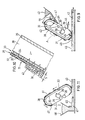
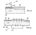
- a screen 31 constituted by a weft of wires 32 forming a endless belt, leans, in a portion of its route, against a permeable wall 33, consisting of a wall provided with a number of through holes 34; the screen 31 having permeable regions 36 and non-permeable regions 37.
- the permeable wall 33 together with other non-permeable walls 35, surrounds a chamber 38 into which a pressure drop P- is kept by known means, not shown.
- the screen 31 is wound on rollers 39 capable of moving the screen 31 sliding on the permeable wall 33, in a controlled and synchronised manner with an underlying support 40.
- a container 41 having inside the granular material 42; at the bottom, said container is provided with a opening leading near to the screen 31 in the route portion where the chamber 38 is present: in this portion therefore, the granular material will be attracted by the permeable regions 36 of the screen 31 and here will stay adherent for a certain thickness S.
- the active side of the screen 31 designed to adhere to the granular material 42, is turned downwards.
- the collected granular material that rises adherent to the screen 31 will be automatically and continuously replaced by natural sliding fall from the container 41.
- a scraping blade 44 in order to level the layer of granular material 42.
- the granular material 42 is kept adherent due to the presence of the chamber 38 in pressure drop, while, downwards, near the support 40, the granular material remains n on the support 40 due to lack of pressure drop and gravity effect; the transfer can be aided through the action of other means as for example a body 45, having a suitable vibration and in contact to the screen 31.
- a cleaning system of the screen 31 can be advantageously placed, for example a sucking mouth 46.
- the screen 31 can work away from the support 40 but may also work in contact with it.
- This second possibility is very advantageous when said support 40 is constituted by a layer of another granular material; in this case the granular material 42 will penetrate into the support 40, keeping it levelled and furthermore the pattern will result better defined due to the absence of falling and sliding of said granular material 42. Said penetration can be achieved by forcing said material 42 into the levelled support 40, in such a case the granular material 42, displacing automatically the other granular material of the support 40, replaces it and keep it levelled, or said penetration can be achieved introducing said granular material 42 into cavities 49 already provided in the support 40.
- the invention is used to take in a selective manner granular material from an underlying support 40; in such a case the taken granular material 47 can be easily recycled causing it to fall into an upstream distributing device 48; this use is particularly useful to modify in a controlled manner the thickness of a layer of granular material, or to obtain said cavities 49, in which a different material may be introduced.
- the invention allows an effective control of the dosing of the granular material simply regulating the pressure drop level in the chamber 38; for example, using:
- the invention can be carried out in different forms, for example: with movable or stationary planar screens, with drum-shaped screens, for applications on the movable support 40 (as in the explained examples) or stationary. In this last event, since the support 40 is stationary, the apparatus will be caused to translate.
- the invention is also suitable for transferring material in form of great scales or tesserae without real limits of dimension, particularly valuable aesthetic effects being obtainable using these materials, as for example mosaic surfaces or imitations of natural stones.
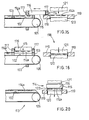
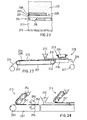
- the apparatus 101 ( Figure 12) includes a belt 102 of permeable to air material, for example of thin metal mesh or texture material, said belt, having on its external surface some separating walls 103 forming compartments of dimensions corresponding to the dimensions of the tile 104, is moved in a controlled way by rollers 105.
- Said drawer transfer means 114 includes a porous diaphragm 115 overhung by a chamber 116 suitable for being depressurised by well known means, not shown, and enclosed by side walls forming a frame 117 axially movable with reference to said porous screen 115.
- the drawer transfer means 114 is horizontally movable from a position overhanging the terminal portion 113 of the belt 102 (as in the Figures 12, 16, 17 and 18) to a position at the inside of the mould 118 in its open configuration (as in the Figures 14 and 20).
- Said mould 118 is constituted by a lateral frame die 119, a lower punch 120 and an upper punch 121; obviously a mould of the type known as "double mirror" may also be used, that is a mould with two axially movable side matrices or also any other suitable mould.
- the belt 102 advances one step, discharging the exceeding granular material 108 and bringing a new portion of the granules bulk 114a in a suitable position for drawing.
- a lower trimming on the granules 108 may be performed, to remove a possible excess of granules or to level the surface through a scraper 124, such material automatically mixing with the other excesses of granules 123.
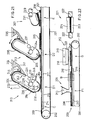
- the apparatus includes an endless belt 201 in a material permeable to the air wound on rollers 202, at least one of them being provided with members for the rotation, not shown.
- the upper branch of the said belt 201 may be advanced step by step to the right with a step width equal to the distance between each station and next one.
- a plurality of decorating stations D1, D2 each provided with decorating means 213 capable to apply further decorating materials 204, 205.
- Such a decoration can be obtained from powdery or granular material at a dry state, as in the example, or from powdery or granular material kneaded with a liquid mean according to well known technologies; in the first case there will be preferably a subsequent station (not shown) to fix the said decorating materials, for example by applying a fixing agent, in the second case there will be preferably a subsequent dry station (not shown).
- the whole portion of the belt 201 from the station C to the station F1 lays on a permeable support 214, for example due to presence of the small holes 215; the said support 214 together with a sealing wall 216 bounds a chamber 217, in which a light pressure drop is maintained through well known means, not shown.
- a pressure drop has the function to maintain steadily in its position on the belt 201, the sheet 203 and the respective decalcomania 209.
- the transfer means 212 is constituted by a permeable wall 218, overhung by a chamber 219 suitable for being depressurised through well known means, not shown, and by lateral walls projecting downwards and forming a relatively thin, or "wedge" shaped, frame 220, that is walls capable to penetrate into the powder layer 210 without appreciably throwing it into disorder.
- Said drawer transfer means 212 may be translated from a position overhanging the terminal station G of the belt 201 (as in the Figures 22 and 24) to a position at the inside of the open mould 221 (as in the Figures 25 and 26)
- Said mould 221 is constituted by a side frame-shaped die 222, a lower punch 223 and an upper punch 224; obviously a mould of the type known as "double mirror" may be used, that is a mould with two movable side dies or any other suitable mould.
- the belt 201 advances one step unloading the excess 224 of powders 210 and bringing a new decalcomania 209 with respective layer of powders 210 to a drawing position.
- the pressure drop in the chamber 219 is activated during the drawing step ( Figure 24), is maintained during the translation step ( Figure 25) and is deactivated during the unloading phase in the mould 221 ( Figure 26).
- the combination just described that is the transfer of the powder layer 210 and the low permeability layer by means of said pressure drop apparatus 212, is particularly effective and congenial, because, forming said low permeability layer a substantially impermeable wall, the powders 210 may be supported at the inside of the apparatus by a "static pressure drop" of minimum value.
- a higher pressure drop and of dynamic type for supporting the powders 210 that is a pressure drop with a continuous air flow through the powders 210, which could produce separations between the different granular components of the powders 210 and decomposition of the aesthetic aspect of the decoration.
- decalcomania 209 may be replaced with a thin sheet of paper or plastic material, or a low permeability layer, designed to form said substantially impermeable wall to support the powders 210, while the decorating materials may be arranged in different position, for example on the powders 210 and directly in contact with the permeable wall 218.
- the decalcomanias 209 may be prepared in advance so that the stations D and E may be omitted.
- the transfer equipments may be of any known type, for example capable to move the terminal portion of the belt 201 from an external position to an internal position in the mould 221, the mould being opened so that the decalcomania 209 with its layer of powders 210 may be arranged in it.
- the pressing may be made directly on the belt 201, in this case the transfer apparatus being constituted by the belt 201 itself.
- the sheets 203 may have a peripheral plan dimension like that of the tile 211, but may be constituted also by a thin continuous belt, for example of heat-fusible plastic material that, in such a case, may be automatically cut to a given dimension by the same frame 220 heated to a suitable temperature.
- said thin continuous belt 225 lying on the belt 201 during the passage under the various stations D, E, F1, is dragged into the open mould 226 together with the decorating material 204, 205 and the powders 210; in such a case said thin continuous belt 225 is not cut and can therefore be detached and wound as a coil 227 downstream the mould after pressing has occurred.
- Said thin continuous belt 225 may have a thickness of some hundredths of millimetre or a fraction of hundredth of millimetre, such a configuration beyond the advantage of a low cost (mainly if it consists of material recoverable by recycling) allows the tile surface to be obtained having a shape exactly matching the profile of the underlying die 228 as in a usual mould, without being even necessary cleaning operations of the die 228 itself.
- Said mould 226 is provided with a side frame 229 able to penetrate into the powder 210 without substantially throwing it into disorder.
- the low permeability layer may be achieved distributing on the belt 201 a first layer 253 of powdery material 254, preferably on isolated regions with a peripheral extension corresponding to about the peripheral dimension of the tile 211.
- Said powder material 254 will not necessarily be constituted by decorating materials but may be the same material 210 suitable to form the body of the tile 211, or may be an other material with characteristics particularly suitable to the treatment to which it has to be submitted and to the function it has to carry out.
- the packet of layers so arranged is then drawn by the drawer transfer means 212 and transferred to the mould 221, as already described.
- the advantage of such a version consists in the fact that, even if the transfer means 212 works with a "static pressure drop", there is no foreign material that has to be detached and removed from the pressed tile 211, because said layer 253 constitutes an integral portion of the tile 211; furthermore, the compacting of said layer 253 is particularly easy because said layer has a small thickness so that rollers of great diameter are not necessary; considerable pressing forces are not necessary because the area subjected to pressing is somewhat limited.
- the small thickness of the layer 253 allows a good compacting to be obtained in the peripheral regions of the said layer even without lateral containing walls for the powder.
- the belt 201 in this version, can be also advantageously split into two portions, a first portion having a non-permeable surface where the compacting takes place and a second portion having a permeable surface, in order to make easier the working of the transfer means 212.
- the low permeability layer may be obtained by treating the layer 253 with appropriate impermeabilizing substances.
- the invention can be used as mixing apparatus 313 of layered powders, such an apparatus, placed closely above the layer to be modified, during the motion of relative translation, raises the surface layers and leaves them fall subsequently in a downstream position.
- the screen 331 with both permeable regions and non-permeable, the mixing may be obtained only on a selected portion of the layers and/or at different depths, so obtaining special aesthetic effects.
- a mixing device is shown constituted by an ejector 350 provided with an opening shaped as a thin slot 351 arranged transversally with respect to the direction of movement of the underlying layers; if a suitable air is caused to flow through the said slot 351, a mixing of the surface layers will be produced; some of the surface particles will be deeply throw, while some of the deeply placed particles will raise at the surface.
- a permeable screen 331 is associated to said ejector 350, said screen running on a sliding wall 352 and passing under the said ejector 350, such a configuration offering a first advantage consisting in that a selective mixing can be made even in this case, using the screen 331 provided with both permeable and impermeable regions; furthermore, in this case, the ejector slot 351 may be also disposed in a lower position interfering with the layers 310, 312, without producing accumulations of powder because the screen 331 will drag the powder forward; in addition, said arrangement is particularly advantageous because an excessive volatility of the surface powders is avoided.
- a mixing device consisting of a fluid bed route portion on the belt 302. From below the belt 302, constituted by permeable material, as already explained, air is blown, keeping a certain amount of pressure inside a chamber 353.
- the belt 302 slides over the said chamber 353, that is stationary; the air causes a mixing of the layer of powders while goes up, passing through the whole layer; obviously, in this case, also the most deep particles of the layer will be involved in the mixing and sometimes that can be advantageous, if, for example, the decorating powders are applied directly on the belt 302 or are arranged in a middle layer and covered by a base powder layer 305; with the treatment of fluid bed mixing the decorating powders will be distributed at the inside of the whole overhanging bulk and at the surface, with shades of agreeable effects.
- the mixing devices 313 can be used also in conditions different from those up to now described, for example they can be used for applications on an already pressed or fired material or to form decalcomanias or again a layers of powders already loaded in a mould can be mixed. Furthermore, the layer to be mixed can be kept stationary while the mixing device 313 translates.
- the apparatus according to the invention makes possible therefore to obtain an optimal and uniform loading of the mould in a single step, making possible, in addition, to apply an unlimited number of different decorating layers with well defined patterns and to mix them with each other in a controllable and selective manner, which is particularly productive and advantageous.
Landscapes
- Engineering & Computer Science (AREA)
- Manufacturing & Machinery (AREA)
- Chemical & Material Sciences (AREA)
- Ceramic Engineering (AREA)
- Mechanical Engineering (AREA)
- Press-Shaping Or Shaping Using Conveyers (AREA)
- Finishing Walls (AREA)
Abstract
Description
- a
feeder 107 ofgranules 108 forming a base layer; - an
apparatus 109 for transferring granules, that takes a surface portion of thegranules 108 in a selective manner bringing the granules again into thefeeder 107, forming somecavities 110; - an
apparatus 111 for transferring granules, capable to deposit on the basic layer 108 a differentgranular material 112;
Claims (35)
- Transfer means arranged for transferring a granular material, including screen means through which an operating fluid acts on said granular material.
- Transfer means according to claim 1, wherein said screen means includes regions non-permeable to said operating fluid.
- Transfer means according to claim 1, or 2, wherein said screen means is surrounded by frame means suitable for containing said granular material.
- Transfer means according to any of preceding claims, wherein said screen means is arranged in the form of a endless belt.
- Transfer means according to any of preceding claims, wherein said screen means communicates with chamber means in which said operating fluid is contained.
- Transfer means according to claim 5, wherein said chamber means are provided with at least one opening through which said operating fluid flows out said chamber means to act on said granular material.
- Transfer means according to claim 5, wherein said chamber means are provided with at least one opening through which said operating fluid is drawn back into the said chamber means in order to withdraw said granular material.
- Transfer means according to claim 6, or 7, wherein said at least one opening is arranged adjacent to an efflux opening of container means in which said granular material is contained.
- Transfer means according to claim 8, wherein said efflux opening is turned towards said screen means in a region of said screen means having an outer face facing downwards.
- Transfer means according to any of preceding claims and further comprising support belt means arranged to support said granular material.
- Transfer means according to claim 10, wherein said belt means includes projections suitable to define compartments for containing said granular material.
- Transfer means according to claim 10, or 11, wherein said supporting belt means defines said screen means.
- Transfer means according to any of claims 10 to 12, wherein at least two initially distinct layers of said granular material are arranged on said belt means.
- Transfer means according to any of claims 10 or 11, or 13 when depending on claims 10 or 11, wherein said screen means is arranged above said granular material.
- Transfer means according to any of preceding claims, wherein said screen means are movable in order to be introduced in a mould suitable for forming ceramic tiles.
- Transfer means according to any of preceding claims, wherein said granular material include one layer substantially non-permeable to said operating fluid.
- Transfer means according to claim 16, wherein said substantially non-permeable layer includes ceramic material.
- Transfer means according to claim 17, and further comprising means for forming said substantially non-permeable layer.
- Transfer means according to claim 18, wherein said means for forming said substantially non-permeable layer comprises means for distributing decorating means on a sheet support.
- Method for transferring granular material comprising acting with an operating fluid on a granular material causing said operating fluid to pass through permeable regions of screen means.
- Method according to claim 20, wherein said granular material is peripherally contained by frame means.
- Method according to any of claims 20 or 21 wherein the said acting comprises blowing said operating fluid through said screen means.
- Method according to any of claims 20 to 22, wherein said acting comprises sucking said operating fluid-through said screen means.
- Method according to claim 22, or 23, wherein said acting takes place near an efflux opening of container means in which said granular material is contained.
- Method according to claim 24, wherein said acting takes place while said screen means have one of their outer faces interacting with said granular material and facing downwards.
- Method according to any of claims 20 to 25, wherein said acting takes place while said screen means supports said granular material.
- Method according to any of claims 20 to 25, wherein said acting takes place while said screen means lies above said granular material.
- Method according to any of claims 20 to 27, wherein said granular material is distributed in at least two layers.
- Method according to claim 28, wherein said granular material is submitted to the action of said operating fluid in such a manner that said at least two layers are at least partially mixed with each other.
- Method according to any of claims 20 to 29, wherein said acting comprises transferring said granular material into a mould for forming ceramic tiles.
- Method according to any of claims 20 to 30, and further comprising providing said granular material with a substantially non-permeable layer.
- Method for transferring granular material to a pressing station for ceramic tiles, comprising arranging said granular material on thin belt means, unwinding said belt means from a coil arranged upstream the pressing station and rewinding said belt means in form of a coil downstream the said pressing station.
- Method to prepare a layer of powders designed to be pressed in the form of ceramic tile, characterised in that it comprises the following steps: arranging on a support surface superimposed layers of different powders; acting with a fluid on said superimposed layers of different powders in order to mix them with each other.
- Method to prepare powders suitable for forming ceramic products comprising arranging at least one layer of powders on supporting means, selectively removing upper regions of said at least one layer to obtain cavities in said at least one layer, then filling said cavities with further powders.
- Method according to claim 34, or 33, or 32, and comprising the use of means according to one or more of preceding claims.
Priority Applications (3)
| Application Number | Priority Date | Filing Date | Title |
|---|---|---|---|
| EP99118949A EP0997248B1 (en) | 1998-09-28 | 1999-09-27 | Method and means for transfer of granular materials |
| DE69918511T DE69918511T2 (en) | 1998-09-28 | 1999-09-27 | Method and device for transferring granular material |
| AT99118949T ATE270608T1 (en) | 1998-09-28 | 1999-09-27 | METHOD AND DEVICE FOR TRANSFERRING GRANULAR MATERIAL |
Applications Claiming Priority (10)
| Application Number | Priority Date | Filing Date | Title |
|---|---|---|---|
| IT97MO000233 IT1297422B1 (en) | 1997-12-23 | 1997-12-23 | Granular material transfer method |
| ITMO970233 | 1997-12-23 | ||
| ITMO980196 | 1998-09-28 | ||
| ITMO980197 | 1998-09-28 | ||
| ITMO980197 IT1304643B1 (en) | 1998-09-28 | 1998-09-28 | Granular material transfer method |
| ITMO980196 IT1304642B1 (en) | 1998-09-28 | 1998-09-28 | Granular material transfer method |
| ITMO980261 | 1998-12-22 | ||
| ITMO980262 | 1998-12-22 | ||
| ITMO980261 IT1304940B1 (en) | 1998-12-22 | 1998-12-22 | Granular material transfer method |
| ITMO980262 IT1304941B1 (en) | 1998-12-22 | 1998-12-22 | Granular material transfer method |
Publications (3)
| Publication Number | Publication Date |
|---|---|
| EP0927687A2 true EP0927687A2 (en) | 1999-07-07 |
| EP0927687A3 EP0927687A3 (en) | 1999-08-18 |
| EP0927687B1 EP0927687B1 (en) | 2004-05-26 |
Family
ID=27517899
Family Applications (1)
| Application Number | Title | Priority Date | Filing Date |
|---|---|---|---|
| EP98124583A Expired - Lifetime EP0927687B1 (en) | 1997-12-23 | 1998-12-23 | Method and means for transfer of granular materials |
Country Status (3)
| Country | Link |
|---|---|
| EP (1) | EP0927687B1 (en) |
| DE (1) | DE69824134D1 (en) |
| ES (1) | ES2223154T3 (en) |
Cited By (27)
| Publication number | Priority date | Publication date | Assignee | Title |
|---|---|---|---|---|
| EP0990496A1 (en) * | 1998-09-16 | 2000-04-05 | S.I.T.I. S.p.A. Società Impianti Termoelettrici Industriali | Device for feeding a pressing apparatus, pressing apparatus and pressing method |
| EP0997248A3 (en) * | 1998-09-28 | 2000-12-20 | Carlo Antonio Camorani | Method and means for transfer of granular materials |
| DE10108327C1 (en) * | 2001-02-21 | 2002-09-05 | Klingenberg Dekoramik Gmbh | Decoration machine for tiles, porcelain or cement products, had control on charging slide of press for raising and lowering application roller. |
| EP1175984A3 (en) * | 2000-07-26 | 2003-07-30 | L.B. Officine Meccaniche S.p.A. | Pneumatic powder dispensing device for loading ceramic moulds |
| EP1358982A3 (en) * | 2002-05-03 | 2004-05-19 | Tecno-Europa S.r.l. | Processing unit and relative method for decorating ceramic products |
| EP1447190A3 (en) * | 2002-08-12 | 2005-03-09 | MIRA di ALGERI, Maris | Method for making tiles |
| WO2005025828A1 (en) * | 2003-09-17 | 2005-03-24 | Mira Di Algeri Maris | Method and apparatus for decorating |
| EP1334811A3 (en) * | 2002-02-07 | 2005-04-20 | System S.p.A. | A process and apparatus for decorating ceramic slabs or tiles |
| EP1375099A3 (en) * | 2002-06-20 | 2005-05-04 | System S.p.A. | A device for loading powders |
| EP1375097A3 (en) * | 2002-06-28 | 2005-06-29 | L.B. Officine Meccaniche S.p.A. | Plant for creating pre-compacted ceramic powder blanks and for feeding them to the forming cavity of a press |
| EP1419863A3 (en) * | 2003-01-24 | 2005-11-23 | T.S.C. S.p.A. | Equipment for applying powdery products on items for decorating the same |
| EP1454727A3 (en) * | 2003-03-04 | 2005-12-07 | T.S.C. S.p.A. | Device for application of powdery and/or granular products onto corresponding articles, in particular ceramic tiles, for decoration thereof |
| WO2005097447A3 (en) * | 2004-04-08 | 2006-03-09 | Lb Officine Meccaniche Spa | Apparatuses and methods for obtaining decorated ceramic |
| EP1541308A3 (en) * | 2003-12-11 | 2006-05-24 | Tecnografica Sistemi Welko S.P.A. | Method for manufacturing tiles equipped with veins similar to those of natural stones, and plant for carrying it out |
| EP1745904A3 (en) * | 2005-07-19 | 2009-09-30 | Sacmi Cooperativa Meccanici Imola Societa' Cooperativa | Method for the forming of ceramic tiles or slabs reproducing the typical characteristics of the natural stones and related apparatus |
| US8337947B2 (en) | 2006-02-21 | 2012-12-25 | System S.P.A. | Decorating with powder material |
| CN103466260A (en) * | 2013-09-10 | 2013-12-25 | 杭州中亚机械股份有限公司 | Conveying device |
| CN103466310A (en) * | 2013-09-10 | 2013-12-25 | 杭州中亚机械股份有限公司 | Turning conveying device |
| EP2762284A1 (en) * | 2013-02-01 | 2014-08-06 | SACMI Cooperativa Meccanici Imola Società Cooperativa | A method and a plant for manufacturing cladding slabs and cladding slab |
| WO2015118196A1 (en) | 2014-02-07 | 2015-08-13 | Kerajet, S.A. | Device, method and machine for depositing powdered or granulated solids on a surface |
| CN105034156A (en) * | 2015-08-24 | 2015-11-11 | 佛山市赛普飞特机械有限公司 | 3D cloth decoration method and 3D cloth device applying same |
| CN106736351A (en) * | 2016-12-02 | 2017-05-31 | 芜湖市泰能电热器具有限公司 | A kind of electric heating aluminum pipe assembly line transmitting device |
| CN110480797A (en) * | 2019-08-08 | 2019-11-22 | 李岩 | A kind of environment-protecting intelligent producing device of high density hollow brick |
| CN112265130A (en) * | 2020-11-18 | 2021-01-26 | 广东宏陶陶瓷有限公司 | Distributing machine for producing whole brick adobe |
| US20210069933A1 (en) * | 2018-09-30 | 2021-03-11 | Dongguan City Wonderful Ceramics Industrial Park Co., Ltd. | Mechanical arm material distribution equipment capable of realizing consistence between a whole-body texture and a surface decoration pattern of ceramic tile and control method for mechanical arm material distribution and pattern adjustment |
| US20210114254A1 (en) * | 2018-03-26 | 2021-04-22 | System Ceramics S.P.A. | Method for pressing ceramic slabs |
| IT202000023845A1 (en) * | 2020-10-09 | 2022-04-09 | Technoplants S R L | FURNACE-PRESS OF INCONSISTENT MATERIAL |
Family Cites Families (6)
| Publication number | Priority date | Publication date | Assignee | Title |
|---|---|---|---|---|
| ES461271A1 (en) * | 1977-08-02 | 1978-05-01 | Perez Canales Candido | Screening device for bulk mineral material in powder or granular form |
| JPS5857430B2 (en) * | 1978-10-23 | 1983-12-20 | 四国化成工業株式会社 | Process for producing granular dichloroisocyanuric acid alkali metal salt |
| US4863645A (en) * | 1987-09-29 | 1989-09-05 | Union Oil Company Of California | Apparatus and process for producing particulate sulfur |
| FR2647298A1 (en) * | 1989-05-25 | 1990-11-30 | Billard Jean | Pneumatic single-seed distribution device for a multifunction seeder |
| US5419246B1 (en) * | 1994-08-02 | 1998-06-09 | Kenneth Bibby | Method and apparatus for laying a granular pattern |
| EP0927080A1 (en) * | 1996-09-18 | 1999-07-07 | Kenneth Bibby | Method and apparatus for laying a granular pattern |
-
1998
- 1998-12-23 EP EP98124583A patent/EP0927687B1/en not_active Expired - Lifetime
- 1998-12-23 DE DE69824134T patent/DE69824134D1/en not_active Expired - Lifetime
-
1999
- 1999-09-27 ES ES99118949T patent/ES2223154T3/en not_active Expired - Lifetime
Cited By (34)
| Publication number | Priority date | Publication date | Assignee | Title |
|---|---|---|---|---|
| EP0990496A1 (en) * | 1998-09-16 | 2000-04-05 | S.I.T.I. S.p.A. Società Impianti Termoelettrici Industriali | Device for feeding a pressing apparatus, pressing apparatus and pressing method |
| EP0997248A3 (en) * | 1998-09-28 | 2000-12-20 | Carlo Antonio Camorani | Method and means for transfer of granular materials |
| EP1175984A3 (en) * | 2000-07-26 | 2003-07-30 | L.B. Officine Meccaniche S.p.A. | Pneumatic powder dispensing device for loading ceramic moulds |
| DE10108327C1 (en) * | 2001-02-21 | 2002-09-05 | Klingenberg Dekoramik Gmbh | Decoration machine for tiles, porcelain or cement products, had control on charging slide of press for raising and lowering application roller. |
| EP1334811A3 (en) * | 2002-02-07 | 2005-04-20 | System S.p.A. | A process and apparatus for decorating ceramic slabs or tiles |
| EP1358982A3 (en) * | 2002-05-03 | 2004-05-19 | Tecno-Europa S.r.l. | Processing unit and relative method for decorating ceramic products |
| EP1375099A3 (en) * | 2002-06-20 | 2005-05-04 | System S.p.A. | A device for loading powders |
| EP1375097A3 (en) * | 2002-06-28 | 2005-06-29 | L.B. Officine Meccaniche S.p.A. | Plant for creating pre-compacted ceramic powder blanks and for feeding them to the forming cavity of a press |
| EP1447190A3 (en) * | 2002-08-12 | 2005-03-09 | MIRA di ALGERI, Maris | Method for making tiles |
| EP1419863A3 (en) * | 2003-01-24 | 2005-11-23 | T.S.C. S.p.A. | Equipment for applying powdery products on items for decorating the same |
| EP1454727A3 (en) * | 2003-03-04 | 2005-12-07 | T.S.C. S.p.A. | Device for application of powdery and/or granular products onto corresponding articles, in particular ceramic tiles, for decoration thereof |
| WO2005025828A1 (en) * | 2003-09-17 | 2005-03-24 | Mira Di Algeri Maris | Method and apparatus for decorating |
| EP1541308A3 (en) * | 2003-12-11 | 2006-05-24 | Tecnografica Sistemi Welko S.P.A. | Method for manufacturing tiles equipped with veins similar to those of natural stones, and plant for carrying it out |
| WO2005097447A3 (en) * | 2004-04-08 | 2006-03-09 | Lb Officine Meccaniche Spa | Apparatuses and methods for obtaining decorated ceramic |
| EP1745904A3 (en) * | 2005-07-19 | 2009-09-30 | Sacmi Cooperativa Meccanici Imola Societa' Cooperativa | Method for the forming of ceramic tiles or slabs reproducing the typical characteristics of the natural stones and related apparatus |
| EP2687347A2 (en) | 2006-02-21 | 2014-01-22 | System Spa | Decorating with powder material. |
| US8337947B2 (en) | 2006-02-21 | 2012-12-25 | System S.P.A. | Decorating with powder material |
| EP2762284A1 (en) * | 2013-02-01 | 2014-08-06 | SACMI Cooperativa Meccanici Imola Società Cooperativa | A method and a plant for manufacturing cladding slabs and cladding slab |
| CN103466260A (en) * | 2013-09-10 | 2013-12-25 | 杭州中亚机械股份有限公司 | Conveying device |
| CN103466310A (en) * | 2013-09-10 | 2013-12-25 | 杭州中亚机械股份有限公司 | Turning conveying device |
| CN103466260B (en) * | 2013-09-10 | 2015-11-25 | 杭州中亚机械股份有限公司 | A kind of feedway |
| CN103466310B (en) * | 2013-09-10 | 2015-11-25 | 杭州中亚机械股份有限公司 | A kind of direction-changing conveying device |
| WO2015118196A1 (en) | 2014-02-07 | 2015-08-13 | Kerajet, S.A. | Device, method and machine for depositing powdered or granulated solids on a surface |
| CN105034156A (en) * | 2015-08-24 | 2015-11-11 | 佛山市赛普飞特机械有限公司 | 3D cloth decoration method and 3D cloth device applying same |
| CN106736351A (en) * | 2016-12-02 | 2017-05-31 | 芜湖市泰能电热器具有限公司 | A kind of electric heating aluminum pipe assembly line transmitting device |
| US20210114254A1 (en) * | 2018-03-26 | 2021-04-22 | System Ceramics S.P.A. | Method for pressing ceramic slabs |
| US12109725B2 (en) * | 2018-03-26 | 2024-10-08 | System Ceramics S.P.A. | Method for pressing ceramic slabs |
| US20210069933A1 (en) * | 2018-09-30 | 2021-03-11 | Dongguan City Wonderful Ceramics Industrial Park Co., Ltd. | Mechanical arm material distribution equipment capable of realizing consistence between a whole-body texture and a surface decoration pattern of ceramic tile and control method for mechanical arm material distribution and pattern adjustment |
| US11639013B2 (en) * | 2018-09-30 | 2023-05-02 | Dongguan City Wonderful Ceramics Industrial Park Co., Ltd. | Mechanical arm material distribution equipment capable of realizing consistence between a whole-body texture and a surface decoration pattern of ceramic tile and control method for mechanical arm material distribution and pattern adjustment |
| CN110480797A (en) * | 2019-08-08 | 2019-11-22 | 李岩 | A kind of environment-protecting intelligent producing device of high density hollow brick |
| IT202000023845A1 (en) * | 2020-10-09 | 2022-04-09 | Technoplants S R L | FURNACE-PRESS OF INCONSISTENT MATERIAL |
| EP3981583A1 (en) * | 2020-10-09 | 2022-04-13 | Technoplants S.R.L. | Oven-press of inconsistent material |
| CN112265130A (en) * | 2020-11-18 | 2021-01-26 | 广东宏陶陶瓷有限公司 | Distributing machine for producing whole brick adobe |
| CN112265130B (en) * | 2020-11-18 | 2024-12-27 | 广东宏陶陶瓷有限公司 | A material distribution machine for producing full-body brick blanks |
Also Published As
| Publication number | Publication date |
|---|---|
| DE69824134D1 (en) | 2004-07-01 |
| ES2223154T3 (en) | 2005-02-16 |
| EP0927687B1 (en) | 2004-05-26 |
| EP0927687A3 (en) | 1999-08-18 |
Similar Documents
| Publication | Publication Date | Title |
|---|---|---|
| EP0927687A2 (en) | Method and means for transfer of granular materials | |
| EP1170104B1 (en) | Distributing means for distributing powder material | |
| EP0793565B1 (en) | A method for compacting powders, and a relative apparatus | |
| CN110418701B (en) | Apparatus and method for making ceramic articles | |
| WO2001072489A2 (en) | Object decoration | |
| CN113490809B (en) | Dispensing rod for granular or powdered materials | |
| CN102225577A (en) | Ceramic brick distribution equipment and process | |
| CN113165205B (en) | Machine for dry decoration of ceramic tiles | |
| US6391236B1 (en) | Process and plant for forming ceramic tiles and the like | |
| EP0997248B1 (en) | Method and means for transfer of granular materials | |
| US12564982B2 (en) | Compacting machine and plant for manufacturing ceramic articles | |
| EP1447190A2 (en) | Method for making tiles | |
| EP4142996B1 (en) | Method and machine for the surface treatment of a base ceramic article | |
| ITMO20010253A1 (en) | FEEDING SYSTEM OF A PRESS FOR THE FORMING OF CERAMIC OBJECTS | |
| WO2003099737A2 (en) | An apparatus and a process for production of decorated ceramic tiles | |
| ITMO20060297A1 (en) | APPARATUS AND SLAB | |
| ITMO990021A1 (en) | METHOD AND DEVICE TO FEED THE MOLD IN THE PRESSING OF CERAMIC TILES. | |
| ITMO980196A1 (en) | MEANS FOR TRANSFER OF GRANULAR MATERIAL PARTICULARLY SUITABLE FOR THE DECORATION OF CERAMIC TILES | |
| PT101962A (en) | Machine and process for making decorations with powder materials on ceramic tiles | |
| ITRE20010061A1 (en) | POWDER COMPACTION METHOD TO FORM CERAMIC TILES, AND EQUIPMENT TO IMPLEMENT THE METHOD | |
| ITMO980262A1 (en) | METHOD AND DEVICE TO DECORATE CERAMIC TILES ON PRESSING. | |
| ITMO980197A1 (en) | DEVICE FOR FEEDING THE MOLD IN THE PRESSING OF CERAMIC PRODUCTS AND RELATED METHOD | |
| EP1219418A2 (en) | Machine for continuous surface decoration of products, particularly ceramic tiles | |
| ITMO20000132A1 (en) | SYSTEM FOR FORMING CERAMIC POWDERS AND CERAMIC TILES | |
| ITMO980261A1 (en) | DEVICE AND METHOD FOR MAKING DECORATIONS, WITH POWDERED MATERIALS, ON CERAMIC TILES. |
Legal Events
| Date | Code | Title | Description |
|---|---|---|---|
| PUAI | Public reference made under article 153(3) epc to a published international application that has entered the european phase |
Free format text: ORIGINAL CODE: 0009012 |
|
| PUAL | Search report despatched |
Free format text: ORIGINAL CODE: 0009013 |
|
| AK | Designated contracting states |
Kind code of ref document: A2 Designated state(s): DE ES FR IT PT |
|
| AX | Request for extension of the european patent |
Free format text: AL;LT;LV;MK;RO;SI |
|
| AK | Designated contracting states |
Kind code of ref document: A3 Designated state(s): AT BE CH CY DE DK ES FI FR GB GR IE IT LI LU MC NL PT SE |
|
| AX | Request for extension of the european patent |
Free format text: AL;LT;LV;MK;RO;SI |
|
| 17P | Request for examination filed |
Effective date: 20000210 |
|
| AKX | Designation fees paid |
Free format text: AT BE CH CY DE LI |
|
| RBV | Designated contracting states (corrected) |
Designated state(s): DE ES FR IT PT |
|
| 17Q | First examination report despatched |
Effective date: 20010605 |
|
| GRAP | Despatch of communication of intention to grant a patent |
Free format text: ORIGINAL CODE: EPIDOSNIGR1 |
|
| GRAS | Grant fee paid |
Free format text: ORIGINAL CODE: EPIDOSNIGR3 |
|
| GRAA | (expected) grant |
Free format text: ORIGINAL CODE: 0009210 |
|
| AK | Designated contracting states |
Kind code of ref document: B1 Designated state(s): DE ES FR IT PT |
|
| PG25 | Lapsed in a contracting state [announced via postgrant information from national office to epo] |
Ref country code: FR Free format text: LAPSE BECAUSE OF NON-PAYMENT OF DUE FEES Effective date: 20040526 |
|
| REF | Corresponds to: |
Ref document number: 69824134 Country of ref document: DE Date of ref document: 20040701 Kind code of ref document: P |
|
| PG25 | Lapsed in a contracting state [announced via postgrant information from national office to epo] |
Ref country code: DE Free format text: LAPSE BECAUSE OF FAILURE TO SUBMIT A TRANSLATION OF THE DESCRIPTION OR TO PAY THE FEE WITHIN THE PRESCRIBED TIME-LIMIT Effective date: 20040827 |
|
| PG25 | Lapsed in a contracting state [announced via postgrant information from national office to epo] |
Ref country code: ES Free format text: LAPSE BECAUSE OF FAILURE TO SUBMIT A TRANSLATION OF THE DESCRIPTION OR TO PAY THE FEE WITHIN THE PRESCRIBED TIME-LIMIT Effective date: 20040906 |
|
| PLBE | No opposition filed within time limit |
Free format text: ORIGINAL CODE: 0009261 |
|
| STAA | Information on the status of an ep patent application or granted ep patent |
Free format text: STATUS: NO OPPOSITION FILED WITHIN TIME LIMIT |
|
| 26N | No opposition filed |
Effective date: 20050301 |
|
| EN | Fr: translation not filed | ||
| PG25 | Lapsed in a contracting state [announced via postgrant information from national office to epo] |
Ref country code: PT Free format text: LAPSE BECAUSE OF NON-PAYMENT OF DUE FEES Effective date: 20041026 |
|
| PGFP | Annual fee paid to national office [announced via postgrant information from national office to epo] |
Ref country code: IT Payment date: 20071228 Year of fee payment: 10 |
|
| PG25 | Lapsed in a contracting state [announced via postgrant information from national office to epo] |
Ref country code: IT Free format text: LAPSE BECAUSE OF NON-PAYMENT OF DUE FEES Effective date: 20081223 |