EP0931228B1 - Dispositif de commande pour une transmission a variation continue - Google Patents
Dispositif de commande pour une transmission a variation continue Download PDFInfo
- Publication number
- EP0931228B1 EP0931228B1 EP98966760A EP98966760A EP0931228B1 EP 0931228 B1 EP0931228 B1 EP 0931228B1 EP 98966760 A EP98966760 A EP 98966760A EP 98966760 A EP98966760 A EP 98966760A EP 0931228 B1 EP0931228 B1 EP 0931228B1
- Authority
- EP
- European Patent Office
- Prior art keywords
- disc
- driving shaft
- rotation
- sleeves
- translation
- Prior art date
- Legal status (The legal status is an assumption and is not a legal conclusion. Google has not performed a legal analysis and makes no representation as to the accuracy of the status listed.)
- Expired - Lifetime
Links
- 230000005540 biological transmission Effects 0.000 title claims abstract description 28
- 238000002485 combustion reaction Methods 0.000 claims abstract description 12
- 230000035515 penetration Effects 0.000 claims abstract description 5
- 230000033001 locomotion Effects 0.000 claims description 14
- 230000008878 coupling Effects 0.000 claims description 13
- 238000010168 coupling process Methods 0.000 claims description 13
- 238000005859 coupling reaction Methods 0.000 claims description 13
- 239000007858 starting material Substances 0.000 claims description 12
- 238000006243 chemical reaction Methods 0.000 claims description 7
- 230000004913 activation Effects 0.000 claims description 4
- 230000009471 action Effects 0.000 claims description 3
- 238000005096 rolling process Methods 0.000 description 6
- 230000000694 effects Effects 0.000 description 5
- 238000011017 operating method Methods 0.000 description 5
- 230000008901 benefit Effects 0.000 description 4
- 238000010276 construction Methods 0.000 description 3
- 238000001514 detection method Methods 0.000 description 3
- 210000003746 feather Anatomy 0.000 description 3
- 230000003213 activating effect Effects 0.000 description 2
- 230000008859 change Effects 0.000 description 2
- 230000001965 increasing effect Effects 0.000 description 2
- 230000009347 mechanical transmission Effects 0.000 description 2
- 230000009467 reduction Effects 0.000 description 2
- 230000004044 response Effects 0.000 description 2
- 230000005355 Hall effect Effects 0.000 description 1
- 230000001133 acceleration Effects 0.000 description 1
- 230000003042 antagnostic effect Effects 0.000 description 1
- 230000003247 decreasing effect Effects 0.000 description 1
- 238000010586 diagram Methods 0.000 description 1
- 230000001939 inductive effect Effects 0.000 description 1
- 238000012423 maintenance Methods 0.000 description 1
- 238000000034 method Methods 0.000 description 1
Images


Classifications
-
- F—MECHANICAL ENGINEERING; LIGHTING; HEATING; WEAPONS; BLASTING
- F16—ENGINEERING ELEMENTS AND UNITS; GENERAL MEASURES FOR PRODUCING AND MAINTAINING EFFECTIVE FUNCTIONING OF MACHINES OR INSTALLATIONS; THERMAL INSULATION IN GENERAL
- F16H—GEARING
- F16H55/00—Elements with teeth or friction surfaces for conveying motion; Worms, pulleys or sheaves for gearing mechanisms
- F16H55/32—Friction members
- F16H55/52—Pulleys or friction discs of adjustable construction
- F16H55/56—Pulleys or friction discs of adjustable construction of which the bearing parts are relatively axially adjustable
-
- F—MECHANICAL ENGINEERING; LIGHTING; HEATING; WEAPONS; BLASTING
- F16—ENGINEERING ELEMENTS AND UNITS; GENERAL MEASURES FOR PRODUCING AND MAINTAINING EFFECTIVE FUNCTIONING OF MACHINES OR INSTALLATIONS; THERMAL INSULATION IN GENERAL
- F16H—GEARING
- F16H63/00—Control outputs from the control unit to change-speed- or reversing-gearings for conveying rotary motion or to other devices than the final output mechanism
- F16H63/02—Final output mechanisms therefor; Actuating means for the final output mechanisms
- F16H63/04—Final output mechanisms therefor; Actuating means for the final output mechanisms a single final output mechanism being moved by a single final actuating mechanism
- F16H63/06—Final output mechanisms therefor; Actuating means for the final output mechanisms a single final output mechanism being moved by a single final actuating mechanism the final output mechanism having an indefinite number of positions
- F16H63/062—Final output mechanisms therefor; Actuating means for the final output mechanisms a single final output mechanism being moved by a single final actuating mechanism the final output mechanism having an indefinite number of positions electric or electro-mechanical actuating means
Definitions
- the present invention relates to an actuating device for continuously variable transmission, that is to say, for transmission with a velocity ratio which can be varied gradually.
- the present actuating device may be applied to transmissions comprising a driving pulley and a driven pulley, connected to one another by a belt, preferably with a trapezoidal cross-section, for the transmission of motion between the two pulleys.
- At least one of the pulleys has a diameter which can be varied gradually, upon which the drive belt is wound, and which determines the velocity ratio.
- the actuating device referred to in the present invention can be successfully applied to any type of variable transmission with a ratio which may be varied gradually and in a stepless manner, even with transmission systems other than the belt and pulleys, for example, in the transmissions with friction wheels with or without intermediate elements such as balls, discs, etc.
- the device is used, in particular, in the mechanical transmissions of mopeds and small scooters, to which the following description refers, without limiting the scope of application of the invention.
- At least one pulley is embodied in such a way as to comprise two separate discs.
- Said pulley may be mounted on the driving shaft, as is the case on most scooters, or on the driven shaft, as happens on some mopeds, although the operating principle remains the same.
- the references made here are to the version in which the pulley is mounted on the driving shaft.
- the two discs of the pulley are, therefore, mounted coaxial with the driving shaft, with which they are integral during rotation.
- the outer surfaces of the discs are shaped so that together they delimit a groove between them which houses the flexible element.
- the discs are mounted on the driving shaft, the first in a fixed position and the second in such a way that it can slide, translating along said shaft and varying the width of the groove, allowing the flexible element to be positioned at various distances from the axis of rotation of the driving shaft, corresponding to variations in the velocity ratio between the driving shaft and the driven shaft.
- speed variators of the known type envisage automatic adjustment devices, which effect the necessary corrective action, making use of the forces of inertia induced by the rotation of the driving shaft on masses that are mobile on suitably shaped races made in the mobile disc of the pulley, or the masses are mobile about a hinge, in such a way that they act upon at least a sliding disc of the pulley.
- the masses cause the pulley disc which can slide to move along the axis of rotation, overcoming a resistance created by antagonistic elastic reaction elements, thus narrowing the groove and gradually increasing the distance between the belt and the axis of rotation of the driving shaft; the opposite occurs when the driving shaft speed drops and the elastic reaction elements, overcoming the forces of inertia, create a different equilibrium, corresponding with the widening of the groove and a reduction in the distance between the belt and the axis of rotation.
- Speed variators of the above-mentioned type have many advantages, including their extremely simple construction, reliable, safe operation, the overall speed variator being compact and lightweight.
- the speed of the locomotion means under the various conditions of resistance to forward movement during use, is closely linked to the construction parameters of the speed variator, there being no possibility of modifying it, nor of modulating the performance at the discretion of and according to the requirements of the driver.
- the speed variator effect a variation in the velocity ratio other than that determined by the inherent construction characteristics of the device comprising the masses. Since the masses are located on the driving shaft and rotate with it, they may unbalance the driving shaft and generate a greater moment of inertia, influencing the changes in the speed of the internal combustion engine because they have the effect of an additional fly-wheel.
- the moment of inertia varies according co the distance from axis of rotation of the masses which control the mobile disc, so that the response of the internal combustion engine to speed variations depends on the position of the masses. This effect must be avoided for obtaininig unvarying operating features of the internal combustion engine.
- non-stage transmission in a vehicle run by a driving source such as an engine and a motor.
- the non-stage transmission comprises a drive pulley the groove width thereof is increased or decreased by a change gear ratio changing means using a motor as its driving source, so that the change gear ratio of the non-stage transmission can be varied.
- the motor is controlled in response to output signals from a throttle opening sensor, an engine revolutions sensor and a vehicle speed sensor.
- the aim of the present invention is to provide an actuating device for the control, in a continuously variable transmission, of a wide and continuous variation in the velocity ratio, which is independent of the speed of rotation of the driving shaft.
- the variation in the velocity ratio can be selected and modulated by the driver according to the specific operating requirements of the apparatus or locomotion means to which the continuously variable transmission is applied.
- a further advantage of the present invention compared with speed variators with mass adjustment, is the greater use of the surfaces of the pulleys, meaning that a pulley with the same diameter can be used to obtain a larger variation in the velocity ratio.
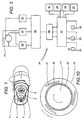
- Figure 1 illustrates a continuously variable transmission 1 designed to transmit mechanical power from a driving shaft 2 to a driven shaft 3, in particular on a scooter or moped, not illustrated.
- the continuously variable transmission 1 basically comprises a flexible element 4 and a pair of pulleys 5, 6, the first of which is coupled to the driving shaft 2, whilst the other is mounted on the driven shaft 3.
- the flexible element 4 consisting of a belt with a trapezoidal cross-section, is mounted on the pulleys 5, 6, which are surrounded and tightly wrapped so as to create sufficient friction between them and the flexible element 4 to transmit the motion from the driving shaft 2 to the driven shaft 3.
- the pulley 5 coupled to the driving shaft 2 comprises ( Figure 2) separate first and second discs 7 and 8, which have truncated cone-shaped outer surfaces 7a, 8a.
- the discs 7, 8 are mounted coaxially on the driving shaft 2, their outer surfaces 7a, 8a being opposite one another and together delimiting an intermediate groove 9 in which the flexible element 4 is housed in such a way that its sides 4e make contact with the outer surfaces 7a and 8a of the discs 7 and 8.
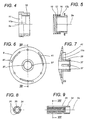
- the first disc 7 has a central hub 31, by means of which the disc 7 is mounted on an end pin 32 on the driving shaft 2, to which it is fixed by tightening a nut 33 that pushes the hub 31 against a fixed wall formed by a tubular cylindrical tube 34, which is coaxially mounted on the driving shaft 2 and makes contact, along the axis of rotation 2a of the latter, with a wall 2b of the driving shaft 2.
- the cylindrical outer surface of the tube 34 has splined seats 35 ( Figures 8 and 9), oriented longitudinally to the axis of rotation 2a of the driving shaft 2. Moreover, the cylindrical inner surface of the tube 34 may have splines which match those on the driving shaft 2, so that it is integral with the latter.
- the second disc 8 has a central hub 36 with longitudinal internal splines 37 similar to those of the tube 34, but shorter.
- the hub 36 is mounted coaxially and in such a way that it can slide on the tube 34, to which it is connected by feather keys 38 oriented parallel with the axis of rotation 2a of the driving shaft 2 and partially housed in the splined seats 35 of the tube 34 and partially in the internal splines 37 of the hub 36 of the second disc 8.
- the driving shaft 2, tube 34 and first disc 7 become integral with one another and can rotate together about the axis of rotation 2a of the driving shaft 2.
- the second disc 8 being connected to the tube 34 by means of the feather keys 38, also becomes integral with the driving shaft 2 during rotation about the axis of rotation 2a, but remains free to slide longitudinally to the driving shaft 2.
- This relative freedom of movement allows the disc 8 to translate on the tube 34, allowing a variation in the width of the groove 9 that houses the flexible element 4 and, therefore, a consequent variation in the velocity ratio of the continuously variable transmission 1 depending on the distances from the axis of rotation 2a assumed by the flexible element in the various positions allowed by the width of the groove 9 deriving from the actual distance between the two discs 7, 8.
- a linear actuating device labelled as a whole with the numeral 10, basically comprising a pair of translation elements 11, 12, motorization means 19, 20 for translation elements and control means 24 suitably connected to the motorization means 19, 20.
- the translation elements 11, 12 are tubular sleeves mounted coaxially on the driving shaft 2.
- a first sleeve 11 comprises a thrust end 11r which, by means of a radial and thrust bearing 45, engages in a matching cavity 11c made in the disc 8 of the first pulley 5, on the opposite side to that facing the flexible element 4.
- the bearing 45 is mounted on the thrust end 11r and inside the cavity 11c in the disc 8 in such a way, for example, by interference fits, that the disc 8 and the first sleeve 11 constitute a unit which can slide integrally in an axial direction relative to the tube 34, but the disc 8 is able to rotate relative to the first sleeve 11.
- the output shaft of an electric motor 19 is fitted with a pinion 52, which in turn engages with the ring gear 51 by means of a pair of coaxial wheel gears 53, 54.
- the latter are made in such a way that they further reduce the rotation of the output shaft of the electric motor 19.
- the ring gear 51 supports a bell 20a, equipped with pulling means 21, 22 for the sleeve 11. Inside the bell 20a is the sleeve 11, which can slide longitudinally to the bell 20a by means of the pulling means 21, 22.
- the sleeve 11 is, therefore, integral with the bell 20a in rotation, but can slide lengthways relative to the latter.
- the disc 8 also comprises ( Figure 10) a coupling, labelled as a whole with the numeral 14.
- This coupling allows the connection of the sleeve 11 to the disc 8 and, therefore, the electric motor 19 to the driving shaft 2, allowing the internal combustion engine to be started by means of the electric motor 19 as it will be explained below.
- the coupling 14 comprises an idle wheel which comprises a crown wheel 42 that supports rolling elements 40, the disc 8 with several walls 41 arranged substantially along a cylindrical surface and the end 11r of the sleeve 11.
- the rolling elements 40 are located between the cylindrical outer surface of the end 11r and the walls 41.
- the rolling elements 40 lock the sleeve 11 to the disc 8, making them integral with one another.
- the sleeve 11 and disc 8 rotate in the opposite direction, they are free to rotate relative to one another, since the rolling elements 40 move away from the walls 41.
- the electric motor 19 causes the ring gear 51, the bell 20a and, therefore, the sleeve 11 to rotate.
- the end 11r of the latter causes connection of the coupling 14 which, by means of the disc 8, feather keys 38 and sleeve 34 makes the driving shaft 2 rotate and so starts the internal combustion engine.
- the second translation element 12 is a sleeve which is locked, for example by interference fits, to a tubular protrusion 13a of the fixed wall 13 of the housing of the speed variator 1.
- the tubular sleeves 11, 12 are respectively fitted with a internal screw 15 and a lead screw 16, as well as ring-shaped grooves 17a, 17b whose diameters are respectively larger than and smaller than the core diameter of the internal screw 15 and lead screw 16.
- the grooves 17a and 17b are positioned longitudinally inside and adjacent to the internal screw 15 and the lead screw 16.
- the tubular sleeves 11, 12 are mounted coaxially on the driving shaft 2, telescopically linked to one another by meshing of the internal screw 15 with the lead screw 16 and also comprise at least one elastic reaction element 18, housed between the sleeves 11 and 12.
- the elastic reaction element 18 exerts a direct action parallel with the axis of rotation 2a and oriented in such a way as to move the sleeves 11, 12 away from one another.
- the motorization means for the sleeves 11, 12 comprise a rotary coupling 20 and activating motor means associated to the coupling.
- the coupling 20 comprises the cylindrical tubular bell 20a, which houses the translation sleeve 11 attached to the second disc 8 of the first pulley 5.
- the bell 20a is equipped with driving means 21, 22 designed to cause the sleeve 11 attached to the second disc 8 of the first pulley 5 to rotate integral with it about the driving shaft 2; they are also designed to allow the sleeve 11 to move freely along the axis of rotation 2a of the driving shaft 2.
- driving means 21, 22 designed to cause the sleeve 11 attached to the second disc 8 of the first pulley 5 to rotate integral with it about the driving shaft 2; they are also designed to allow the sleeve 11 to move freely along the axis of rotation 2a of the driving shaft 2.
- Such effects are preferably obtained by means of slots 21 made in the bell 20a and oriented longitudinally to the driving shaft 2, in which pins 22 projecting radially from the side of the sleeve 11 engage in such a way that they can slide.
- the coupling 20 has a ring gear 51 engaged by a pinion 52 of the drive means using a pair of intermediate gears 53, 54.
- the drive means may be the starter motor 19 of the internal combustion engine that powers the moped or scooter.
- the control means comprise an electronic card 24, schematically illustrated in Figure 3, interfaced on one side with the X, Y power supply poles of the electric motor 19, and on the other side with at least one sensor 26 and two monostable pushbuttons 25, used to switch adjustment of the speed of the continuously variable transmission 1 on and off.
- the pushbuttons 25 (which may be substituted with an equivalent single pushbutton of the bistable type) are, in the case of a means of locomotion constituted by a moped or scooter, positioned on the handlebars. When one of the two pushbuttons 25 is activated, the electronic card 24 causes the motor 19 to rotate in a given direction.
- the card 24 comprises a filter unit 57 for eliminating any electrical interference from the pushbuttons 25 and sensor 26, a microprocessor unit 58 connected to the filter unit 57, an activation unit 59 connected to and controlled by the microprocessor unit 58 for activating the relays 60, and a relay 61.
- the relays 60 activate the electric motor 19 in both directions of rotation.
- the relay 61 activates the brake 31 (if present) which may be fitted on the electric motor 19 and which prevents the electric motor 19 from rotating spontaneously when it is not switched on, for example due to vibrations.
- the sensor 26 transmits to the input of the control card 24 the angular position of the ring gear 51.
- the sensor 26 illustrated in Figure 2 is a Hall effect sensor, which detects the passage of the magnets 27 located on the ring gear 51.
- Detection of the angular movement of the ring gear 51 allows indirect detection of the position of the sliding disc 8 and, therefore, also allows the velocity ratio to be read.
- other types of sensors may be used, for example, inductive sensors.
- the position of the sliding disc 8 may be detected directly by a suitable linear sensor 126, as illustrated in Figure 11.
- the sensor 26 (or 126) allows the microprocessor unit to be informed of the actual velocity ratio achieved and allows a given velocity ratio to be precisely obtained irrespective of the state of charge of the battery which powers the starter motor, wear on the latter, etc.
- the sleeve 11 attach to the second disc 8 of the first pulley 5 slides along the driving shaft 2 and towards (or, vice versa, away from) the first, fixed disc 7, forcing the flexible element 4 away from the axis of rotation 2a (or, vice versa, towards it) and causes the element to gradually move in a direction radial to the discs 7, 8, resulting in an equally gradual variation in the velocity ratio of the continuosly variable transmission 1.
- the driver can control a small or large variation in the speed of the means of locomotion by simply holding down the pushbutton 25 for a short or long period.
- the pushbutton 25 is released, the translation element 11, 12 sliding command stops, the second disc 8 of the first pulley 5 stops in the last position reached relative to the first disc 7 and the velocity ratio of the continuosly variable transmission 1 is maintained until the pushbutton 25 initially pressed is pressed again or, vice versa, the other pushbutton 25 is pressed.
- each time the pushbutton 25 is pressed there is a corresponding given movement of the mobile disc. This movement is checked by the sensor 26.
- the microprocessor unit 58 stores a given number of preset positions of the ring gear 51 and, therefore, of the sliding disc 8, for example 5 or 6 positions, which simulate a conventional 5 or 6 speed gear box and correspond with 5 or 6 different gear ratios.
- the velocity ratio is changed.
- the data contained in the microprocessor unit 58 relative to the various velocity ratios can also be modified, as regards both the number of ratios and the values of the ratios, by connecting the unit 58 to an external computer and suitably modifying the program stored.
- the speed variator is activated in a gradual, automatic manner.
- various operating methods are possible: with maximum acceleration, with maximum speed, with minimum consumption, etc.
- control unit 24 Another useful function which may be added to the control unit 24 is that of limiting and adjusting the speed. This function may be activated by the driver of the vehicle or may be activated automatically by operating the sensor 30 from the outside, using a radio signal or other suitable signal, for example, when the vehicle joins a motorway or enters a town.
- the internal combustion engine of the vehicle rotates anti-clockwise (see the direction of the arrow near the ring gear 51), thus, to allow activation of the control device 10 by means of the starter motor 19, the internal screw 15 and lead screw 16 have a left-hand thread, that is to say, oriented in such a way that the sliding disc 11 is completely screwed onto the fixed disc 12, when the rotary coupling 20 is caused to rotate as the engine of the vehicle is started.
- the sliding sleeve 11 and fixed sleeve 12 achieve maximum reciprocal penetration, along the axis of rotation 2a, whilst the internal screw 15 and lead screw 16 disengage and respectively penetrate grooves 17b and 17a in the two sleeves 11, 12.
- a control device 10 of the above-mentioned type therefore, allows the control in a continuously variable transmission 1, of a variation in the velocity ratio that can be modulated at the discretion of the driver.
- This allows the continuously variable transmission 1 to be used as a gear box, but one in which the number of gears and their division can be freely selected by the driver, according to his/her driving technique.
- the device is also made in a particularly simple, economical solution, with the further advantage of being available in an easily assembled kit that can be adapted to speed variators already in use on mopeds or scooters currently produced.
- Such devices can be advantageously used where the starter motor 19 for the engine is on the same side as the mobile disc 8, thus facilitating operation of the starter motor as the actuating device for the continuously variable transmission.
- the starter motor 19 is in a different position, as illustrated in Figure 11, it is still possible to use it as the actuating device for the speed variator by fitting a control system between them, which may be hydraulic or mechanical with flexible cables.
- the actuating device comprises a hydraulic cylinder 113, activated by the starter motor 19 by means of a connection using a lead screw 112 and a internal screw 111.
- the cylinder 113 is connected by hoses 120 and a valve 115 to an activation cylinder 114, which is in turn connected to the sliding disc 8.
- the valve 115 can be used to interrupt operation of the device for maintenance, etc.
- the screw 112 and the nut screw 111 fulfil a function similar to that of the sleeves 11 and 12 and, therefore, disengage when the engine must be started, then the spring 118 allows the screw 112 to engage with the nut screw 111 and the starter motor 19 may be used to activate the speed variator.
Landscapes
- Engineering & Computer Science (AREA)
- General Engineering & Computer Science (AREA)
- Mechanical Engineering (AREA)
- Transmissions By Endless Flexible Members (AREA)
- Control Of Transmission Device (AREA)
- Friction Gearing (AREA)
- Transmission Devices (AREA)
- Gear-Shifting Mechanisms (AREA)
- Lock And Its Accessories (AREA)
Claims (12)
- Un dispositif de commande pour commander une variation du rapport de vitesse d'une transmission (1) à variation continue destinée à transmettre la puissance d'un moteur à combustion interne d'un arbre moteur (2) à un arbre mené (3), dans lequel la transmission (1) à variation continue comprend un élément flexible (4) conformé en boucle fermée, une première et une deuxième poulies (5, 6) montées, respectivement, sur l'arbre moteur (2) et l'arbre mené (3) et entourées par ledit élément flexible (4), au moins la première poulie (5) ayant un premier et un deuxième disque (7, 8), lesdits disques étant montés coaxiaux à l'arbre moteur (2) avec lequel ils tournent de manière solidaire autour d'un axe de rotation (2a) commun, lesdits premier et deuxième disques (7, 8) ayant des surfaces extérieures (7a, 8a) conformées de manière à délimiter ensemble une gorge (9) qui loge l'élément flexible (4), et étant montés sur l'arbre moteur (2), le premier disque (7) dans une position fixe et le deuxième disque (8) de manière à pouvoir se déplacer par translation le long de l'arbre moteur (2) et varier la largeur de la gorge (9), permettant à l'élément flexible (4) de prendre des positions correspondantes à des distances différentes de l'axe de rotation (2a) de l'arbre moteur (2), ledit dispositif de commande (10) comprenant un actionneur linéaire (11, 12, 13) pour déplacer le disque mobile (8), commandé par des moyens de motorisation (19, 20) indépendants de la vitesse de rotation de l'arbre moteur (2), et des moyens de commande (24) reliés aux moyens de motorisation (19, 20), l'actionneur linéaire comprenant un premier élément de translation (11) pouvant être relié par l'intermédiaire d'un support (45) au deuxième disque (8), de manière à ce que le disque (8) et le premier élément (11) puissent tourner librement l'un par rapport à l'autre et permettre ainsi la translation du disque (8) et de l'élément (11), et un deuxième élément de translation (12) associé au premier élément (11) de manière à ce qu'une rotation relative entre les premier (11) et deuxième (12) éléments soit transformée en une translation relative entre ces mêmes éléments, ledit dispositif étant caractérisé en ce qu'il comprend aussi des moyens de débrayage (17a, 17b, 18) pour débrayer les premier et deuxième éléments, et donc permettre leur rotation libre relative, quand ces mêmes premier et deuxième éléments atteignent le fin de course dans leur translation relative, et en ce que les moyens de motorisation (19, 20) de la paire d'éléments (11, 12) comprennent le démarreur (19) du moteur à combustion interne qui propulse le moyen de locomotion.
- Le dispositif selon la revendication 1, caractérisé en ce que lesdits premier et deuxième éléments de translation sont des manchons tubulaires (11, 12) accouplés de manière télescopique et ayant, respectivement, une vis interne (15) et une vis mère (16) qui sont réciproquement mises en prise et sont destinées à permettre la roto-translation relative des manchons (11, 12) autour et le long de l'axe de rotation (2a) de l'arbre moteur (2).
- Le dispositif selon la revendication 1 ou 2, caractérisé en ce que lesdits moyens de débrayage comprennent des gorges annulaires (17a, 17b) réalisées dans les manchons (11, 12) et situées à une extrémité de la vis interne (15) et de la vis mère (16), et étant destinées à permettre à la vis interne (15) et à la vis mère (16) de se dégager de leur mise en prise réciproque pour permettre aux manchons (11, 12) de tourner librement autour de l'axe de rotation (2a) de l'arbre moteur (2) quand ces mêmes manchons (11, 12) atteignent la condition de compénétration maximale selon la direction de l'axe de rotation (2a).
- Le dispositif selon la revendication 3, caractérisé en ce que la vis interne (15) et la vis mère (16) ont des filets orientés de manière à pouvoir atteindre la condition dans laquelle les manchons (11, 12) tournent librement au moment du démarrage de l'arbre moteur (2) du moteur de propulsion.
- Le dispositif selon la revendication 4, caractérisé en ce que la vis interne (15) et la vis mère (16) ont un filetage à gauche si le moteur de propulsion tourne en sens anti-horaire.
- Le dispositif selon la revendication 4, caractérisé en ce que la vis interne (15) et la vis mère (16) ont un filetage à droite si le moteur de propulsion tourne en sens horaire.
- Le dispositif selon la revendication 4, caractérisé en ce qu'il comprend des éléments de réaction élastique (18) montés entre les manchons (11, 12) de manière à exercer une action directe le long de l'axe de rotation commun (2a) et orientée de manière à éloigner les manchons (11, 12) l'un de l'autre, en maintenant la vis interne (15) et la vis mère (16) en contact réciproque dans la condition de compénétration axiale maximale, lesdits éléments de réaction élastique (18) permettant le rétablissement automatique de la mise en prise entre la vis interne (15) et la vis mère (16) quand le sens de rotation relatif des manchons (11, 12) est inversé, déterminant leur pénétration réciproque.
- Le dispositif selon la revendication 1, caractérisé en ce que les moyens de motorisation comprennent un moteur (19) et un joint rotatif (20), ce dernier ayant des moyens d'entraínement (21, 22) qui entraínent l'élément de translation (11) pouvant être associé au deuxième disque (8) de la première poulie (5), ces moyens d'entraínement (21, 22) étant destinés à faire tourner ensemble le joint (20) et l'élément de translation (11) autour de l'axe (2a) de l'arbre moteur (2) tout en leur permettant, en revanche, de se déplacer librement le long de ce même axe de rotation (2a).
- Le dispositif selon la revendication 8, caractérisé en ce que ledit joint (20) comprend une cloche tubulaire (20a), logeant l'élément de réglage (11) solidaire du deuxième disque (8) de la première poulie (5), les moyens d'entraínement étant constitués par au moins une fente (21) réalisée sur la cloche (20a) et une goupille (22) correspondante, ladite goupille étant associée à l'élément de réglage (11) et coulissant à l'intérieur de la fente (21) de la cloche (20a).
- Le dispositif selon la revendication 1, caractérisé en ce que les moyens de commande comprennent une carte électronique (24) et au moins un bouton de commande (25) pouvant être commuté entre deux états, la carte (24) et le bouton (25) étant fonctionnellement interconnectés avec les moyens de motorisation (19, 20) de manière à activer ou désactiver ces derniers selon l'état de commutation du bouton (25), permettant de commander la variation de distance entre les éléments de translation (11, 12) pendant le temps nécessaire pour moduler le rapport de vitesse de la transmission (1) à variation continue.
- Le dispositif selon la revendication 10, caractérisé en ce que la carte électronique (24) comprend un capteur (26; 126) pour détecter la position réelle du deuxième disque coulissant (8), et donc détecter le rapport de vitesse réel, de manière à obtenir avec précision un rapport de vitesse donné indépendamment de l'état de la batterie qui alimente le démarreur (19) et de l'usure de ce dernier.
- Le dispositif selon la revendication 10 ou 11, caractérisé en ce que la carte électronique (24) comprend une unité de filtrage (57), ladite unité éliminant toutes interférences électriques des boutons (25) et du capteur (26; 126), une unité à microprocesseur (58), reliée à l'unité de filtrage (57), une unité d'activation (59), reliée à l'unité à microprocesseur (58) et commandée par cette dernière, des relais (60, 61) pour commander le moteur (19), ces relais (60, 61) étant activés par l'unité (59).
Applications Claiming Priority (3)
| Application Number | Priority Date | Filing Date | Title |
|---|---|---|---|
| IT97RN000002A IT1297763B1 (it) | 1997-07-10 | 1997-07-10 | Dispositivo per comandare una variazione, modulabile discrezionalmente del rapporto di trasmissione di un variatore continuo di velocita'. |
| ITRN000002 | 1997-07-10 | ||
| PCT/IB1998/001057 WO1999002896A1 (fr) | 1997-07-10 | 1998-07-10 | Actionneur pour transmission a changement de vitesses continu |
Publications (2)
| Publication Number | Publication Date |
|---|---|
| EP0931228A1 EP0931228A1 (fr) | 1999-07-28 |
| EP0931228B1 true EP0931228B1 (fr) | 2002-10-09 |
Family
ID=11407132
Family Applications (1)
| Application Number | Title | Priority Date | Filing Date |
|---|---|---|---|
| EP98966760A Expired - Lifetime EP0931228B1 (fr) | 1997-07-10 | 1998-07-10 | Dispositif de commande pour une transmission a variation continue |
Country Status (9)
| Country | Link |
|---|---|
| EP (1) | EP0931228B1 (fr) |
| JP (1) | JP2001500240A (fr) |
| CN (1) | CN1234860A (fr) |
| AT (1) | ATE225913T1 (fr) |
| AU (1) | AU1550699A (fr) |
| DE (1) | DE69808593T2 (fr) |
| ES (1) | ES2185252T3 (fr) |
| IT (1) | IT1297763B1 (fr) |
| WO (1) | WO1999002896A1 (fr) |
Cited By (3)
| Publication number | Priority date | Publication date | Assignee | Title |
|---|---|---|---|---|
| US7771300B2 (en) | 2005-05-02 | 2010-08-10 | Purdue Research Foundation | Devices for electrically assisting and actuating continuously variable transmissions |
| US7980973B1 (en) | 2006-05-01 | 2011-07-19 | Purdue Research Foundation | Coaxial electrical actuator for continuously variable transmissions |
| US7980972B1 (en) | 2006-05-01 | 2011-07-19 | Purdue Research Foundation | Roller variator for actuating continuously variable transmissions |
Families Citing this family (5)
| Publication number | Priority date | Publication date | Assignee | Title |
|---|---|---|---|---|
| NL1019457C2 (nl) * | 2001-11-30 | 2003-06-03 | Skf Ab | Continu variabel transmissiesysteem in een zelfdragend huis. |
| NL1020498C2 (nl) * | 2002-04-26 | 2003-10-28 | Skf Ab | Continu variabel transmissiesysteem alsmede werkwijze voor het bedrijven van dat systeem. |
| ITMI20022391A1 (it) * | 2002-11-12 | 2004-05-13 | Piaggio & C Spa | Cambio di velocita' a variazione continua |
| ITMI20040365A1 (it) * | 2004-02-27 | 2004-05-27 | Piaggio & C Spa | Sistema di controllo per un cambio di velocita' |
| DE102015203911A1 (de) * | 2015-03-05 | 2016-09-08 | Robert Bosch Gmbh | CVT-Getriebe mit verbesserter Steuerbarkeit mittels eines Anlassers |
Family Cites Families (5)
| Publication number | Priority date | Publication date | Assignee | Title |
|---|---|---|---|---|
| DE2903630C2 (de) * | 1979-01-31 | 1986-09-25 | Warner Electric Brake & Clutch Co., Beloit, Wis. | Kugelgewindetrieb |
| JP2967374B2 (ja) * | 1990-11-20 | 1999-10-25 | 本田技研工業株式会社 | 車両用無段変速機 |
| DE9208832U1 (de) * | 1992-07-02 | 1992-09-10 | Hüppe Form Sonnenschutz- und Raumtrennsysteme GmbH, 2900 Oldenburg | Spindeltrieb |
| JP3196498B2 (ja) * | 1994-05-02 | 2001-08-06 | アイシン・エィ・ダブリュ株式会社 | 車両用変速機の制御装置 |
| IT1275015B (it) * | 1994-09-09 | 1997-07-29 | Piaggio Veicoli Europ | Cambio automatico e/o a marce a cinghia trapezoidale |
-
1997
- 1997-07-10 IT IT97RN000002A patent/IT1297763B1/it active IP Right Grant
-
1998
- 1998-07-10 EP EP98966760A patent/EP0931228B1/fr not_active Expired - Lifetime
- 1998-07-10 WO PCT/IB1998/001057 patent/WO1999002896A1/fr not_active Ceased
- 1998-07-10 AU AU15506/99A patent/AU1550699A/en not_active Abandoned
- 1998-07-10 JP JP11508373A patent/JP2001500240A/ja active Pending
- 1998-07-10 DE DE69808593T patent/DE69808593T2/de not_active Expired - Fee Related
- 1998-07-10 ES ES98966760T patent/ES2185252T3/es not_active Expired - Lifetime
- 1998-07-10 CN CN98800950.1A patent/CN1234860A/zh active Pending
- 1998-07-10 AT AT98966760T patent/ATE225913T1/de not_active IP Right Cessation
Cited By (3)
| Publication number | Priority date | Publication date | Assignee | Title |
|---|---|---|---|---|
| US7771300B2 (en) | 2005-05-02 | 2010-08-10 | Purdue Research Foundation | Devices for electrically assisting and actuating continuously variable transmissions |
| US7980973B1 (en) | 2006-05-01 | 2011-07-19 | Purdue Research Foundation | Coaxial electrical actuator for continuously variable transmissions |
| US7980972B1 (en) | 2006-05-01 | 2011-07-19 | Purdue Research Foundation | Roller variator for actuating continuously variable transmissions |
Also Published As
| Publication number | Publication date |
|---|---|
| DE69808593T2 (de) | 2003-06-05 |
| ATE225913T1 (de) | 2002-10-15 |
| IT1297763B1 (it) | 1999-12-20 |
| ITRN970002A1 (it) | 1999-01-10 |
| WO1999002896A1 (fr) | 1999-01-21 |
| JP2001500240A (ja) | 2001-01-09 |
| ES2185252T3 (es) | 2003-04-16 |
| EP0931228A1 (fr) | 1999-07-28 |
| DE69808593D1 (de) | 2002-11-14 |
| CN1234860A (zh) | 1999-11-10 |
| AU1550699A (en) | 1999-02-08 |
Similar Documents
| Publication | Publication Date | Title |
|---|---|---|
| EP0558752B1 (fr) | Transmission sans paliers pour vehicules | |
| CA2858205C (fr) | Transmission a variation continue, systeme d'embrayage, vehicule et procede de commande de transmission | |
| CA2439356C (fr) | Poulie motrice assurant une transmission a variation continue | |
| EP0931228B1 (fr) | Dispositif de commande pour une transmission a variation continue | |
| JP3162328B2 (ja) | 車載用vベルト式自動変速機 | |
| US20020034995A1 (en) | Continuously-variable-ratio belt transmission assembly | |
| EP0591872A1 (fr) | Transmission à variation continue de vitesse en particulier pour des véhicules à deux roues | |
| JPH06249309A (ja) | 無段変速機 | |
| KR20010014280A (ko) | 차량 클러치용 서보 액츄에이터 | |
| KR100373157B1 (ko) | 무단변속기 | |
| JP2002372140A (ja) | Vベルト式無段変速装置 | |
| JPH0678781B2 (ja) | トロイダル形無段変速機のクリ−プ制御装置 | |
| JPH0710120Y2 (ja) | Vベルト型無段変速機のプ−リ−構造 | |
| SU1739143A1 (ru) | Клиноременный вариатор | |
| TWI337235B (en) | Control system for a gearshift | |
| JPS632686Y2 (fr) | ||
| RU1786325C (ru) | Шкив клиноременного вариатора | |
| KR970003561B1 (ko) | 클러치 및 무단변속기 겸용장치 | |
| JPH0219657Y2 (fr) | ||
| KR200142379Y1 (ko) | 차량 수동변속기의 자동 클러칭 구조장치 | |
| JP3245542B2 (ja) | ベルト式無段変速装置 | |
| WO2016199156A1 (fr) | Moteur à changement de vitesse motorisé et embrayage à actionnement à force faible pour deux-roues | |
| SU1588959A1 (ru) | Вариатор | |
| SU1618945A1 (ru) | Бесступенчата силова передача дл транспортных средств | |
| JPS6227741Y2 (fr) |
Legal Events
| Date | Code | Title | Description |
|---|---|---|---|
| PUAI | Public reference made under article 153(3) epc to a published international application that has entered the european phase |
Free format text: ORIGINAL CODE: 0009012 |
|
| 17P | Request for examination filed |
Effective date: 19990326 |
|
| AK | Designated contracting states |
Kind code of ref document: A1 Designated state(s): AT BE CH DE DK ES FI FR GB GR IE IT LI LU MC NL PT SE |
|
| AX | Request for extension of the european patent |
Free format text: SI PAYMENT 19990330 |
|
| 17Q | First examination report despatched |
Effective date: 20010605 |
|
| GRAG | Despatch of communication of intention to grant |
Free format text: ORIGINAL CODE: EPIDOS AGRA |
|
| GRAG | Despatch of communication of intention to grant |
Free format text: ORIGINAL CODE: EPIDOS AGRA |
|
| GRAH | Despatch of communication of intention to grant a patent |
Free format text: ORIGINAL CODE: EPIDOS IGRA |
|
| GRAH | Despatch of communication of intention to grant a patent |
Free format text: ORIGINAL CODE: EPIDOS IGRA |
|
| GRAA | (expected) grant |
Free format text: ORIGINAL CODE: 0009210 |
|
| AK | Designated contracting states |
Kind code of ref document: B1 Designated state(s): AT BE CH DE DK ES FI FR GB GR IE IT LI LU MC NL PT SE |
|
| AX | Request for extension of the european patent |
Free format text: SI PAYMENT 19990330 |
|
| PG25 | Lapsed in a contracting state [announced via postgrant information from national office to epo] |
Ref country code: LI Free format text: LAPSE BECAUSE OF FAILURE TO SUBMIT A TRANSLATION OF THE DESCRIPTION OR TO PAY THE FEE WITHIN THE PRESCRIBED TIME-LIMIT Effective date: 20021009 Ref country code: GR Free format text: LAPSE BECAUSE OF FAILURE TO SUBMIT A TRANSLATION OF THE DESCRIPTION OR TO PAY THE FEE WITHIN THE PRESCRIBED TIME-LIMIT Effective date: 20021009 Ref country code: FI Free format text: LAPSE BECAUSE OF FAILURE TO SUBMIT A TRANSLATION OF THE DESCRIPTION OR TO PAY THE FEE WITHIN THE PRESCRIBED TIME-LIMIT Effective date: 20021009 Ref country code: CH Free format text: LAPSE BECAUSE OF FAILURE TO SUBMIT A TRANSLATION OF THE DESCRIPTION OR TO PAY THE FEE WITHIN THE PRESCRIBED TIME-LIMIT Effective date: 20021009 Ref country code: AT Free format text: LAPSE BECAUSE OF FAILURE TO SUBMIT A TRANSLATION OF THE DESCRIPTION OR TO PAY THE FEE WITHIN THE PRESCRIBED TIME-LIMIT Effective date: 20021009 |
|
| REF | Corresponds to: |
Ref document number: 225913 Country of ref document: AT Date of ref document: 20021015 Kind code of ref document: T |
|
| REG | Reference to a national code |
Ref country code: GB Ref legal event code: FG4D |
|
| REG | Reference to a national code |
Ref country code: CH Ref legal event code: EP |
|
| REG | Reference to a national code |
Ref country code: IE Ref legal event code: FG4D |
|
| REF | Corresponds to: |
Ref document number: 69808593 Country of ref document: DE Date of ref document: 20021114 |
|
| RAP2 | Party data changed (patent owner data changed or rights of a patent transferred) |
Owner name: P.A. PERCORSI AVANZATI S.R.L. |
|
| PG25 | Lapsed in a contracting state [announced via postgrant information from national office to epo] |
Ref country code: SE Free format text: LAPSE BECAUSE OF FAILURE TO SUBMIT A TRANSLATION OF THE DESCRIPTION OR TO PAY THE FEE WITHIN THE PRESCRIBED TIME-LIMIT Effective date: 20030109 Ref country code: PT Free format text: LAPSE BECAUSE OF FAILURE TO SUBMIT A TRANSLATION OF THE DESCRIPTION OR TO PAY THE FEE WITHIN THE PRESCRIBED TIME-LIMIT Effective date: 20030109 Ref country code: DK Free format text: LAPSE BECAUSE OF FAILURE TO SUBMIT A TRANSLATION OF THE DESCRIPTION OR TO PAY THE FEE WITHIN THE PRESCRIBED TIME-LIMIT Effective date: 20030109 |
|
| NLT2 | Nl: modifications (of names), taken from the european patent patent bulletin |
Owner name: P.A. PERCORSI AVANZATI S.R.L. |
|
| REG | Reference to a national code |
Ref country code: CH Ref legal event code: PL |
|
| REG | Reference to a national code |
Ref country code: ES Ref legal event code: FG2A Ref document number: 2185252 Country of ref document: ES Kind code of ref document: T3 |
|
| ET | Fr: translation filed | ||
| REG | Reference to a national code |
Ref country code: CH Ref legal event code: PK Free format text: DAS PRIORITAETSAKTENZEICHEN WURDE BERICHTIGT: |
|
| PG25 | Lapsed in a contracting state [announced via postgrant information from national office to epo] |
Ref country code: LU Free format text: LAPSE BECAUSE OF NON-PAYMENT OF DUE FEES Effective date: 20030710 Ref country code: IE Free format text: LAPSE BECAUSE OF NON-PAYMENT OF DUE FEES Effective date: 20030710 Ref country code: GB Free format text: LAPSE BECAUSE OF NON-PAYMENT OF DUE FEES Effective date: 20030710 |
|
| PG25 | Lapsed in a contracting state [announced via postgrant information from national office to epo] |
Ref country code: ES Free format text: LAPSE BECAUSE OF NON-PAYMENT OF DUE FEES Effective date: 20030711 |
|
| PGFP | Annual fee paid to national office [announced via postgrant information from national office to epo] |
Ref country code: FR Payment date: 20030711 Year of fee payment: 6 |
|
| PGFP | Annual fee paid to national office [announced via postgrant information from national office to epo] |
Ref country code: DE Payment date: 20030717 Year of fee payment: 6 |
|
| PG25 | Lapsed in a contracting state [announced via postgrant information from national office to epo] |
Ref country code: MC Free format text: LAPSE BECAUSE OF NON-PAYMENT OF DUE FEES Effective date: 20030731 Ref country code: BE Free format text: LAPSE BECAUSE OF NON-PAYMENT OF DUE FEES Effective date: 20030731 |
|
| PLBE | No opposition filed within time limit |
Free format text: ORIGINAL CODE: 0009261 |
|
| STAA | Information on the status of an ep patent application or granted ep patent |
Free format text: STATUS: NO OPPOSITION FILED WITHIN TIME LIMIT |
|
| 26N | No opposition filed |
Effective date: 20030710 |
|
| BERE | Be: lapsed |
Owner name: PERCOSI AVANZATI S.R.L. *PA Effective date: 20030731 |
|
| PG25 | Lapsed in a contracting state [announced via postgrant information from national office to epo] |
Ref country code: NL Free format text: LAPSE BECAUSE OF NON-PAYMENT OF DUE FEES Effective date: 20040201 |
|
| GBPC | Gb: european patent ceased through non-payment of renewal fee |
Effective date: 20030710 |
|
| NLV4 | Nl: lapsed or anulled due to non-payment of the annual fee |
Effective date: 20040201 |
|
| REG | Reference to a national code |
Ref country code: IE Ref legal event code: MM4A |
|
| REG | Reference to a national code |
Ref country code: ES Ref legal event code: FD2A Effective date: 20030711 |
|
| PG25 | Lapsed in a contracting state [announced via postgrant information from national office to epo] |
Ref country code: DE Free format text: LAPSE BECAUSE OF NON-PAYMENT OF DUE FEES Effective date: 20050201 |
|
| PG25 | Lapsed in a contracting state [announced via postgrant information from national office to epo] |
Ref country code: FR Free format text: LAPSE BECAUSE OF NON-PAYMENT OF DUE FEES Effective date: 20050331 |
|
| REG | Reference to a national code |
Ref country code: FR Ref legal event code: ST |
|
| PG25 | Lapsed in a contracting state [announced via postgrant information from national office to epo] |
Ref country code: IT Free format text: LAPSE BECAUSE OF NON-PAYMENT OF DUE FEES Effective date: 20050710 |