EP0931274B1 - Optisches wellenleiterfilter - Google Patents
Optisches wellenleiterfilter Download PDFInfo
- Publication number
- EP0931274B1 EP0931274B1 EP97944968A EP97944968A EP0931274B1 EP 0931274 B1 EP0931274 B1 EP 0931274B1 EP 97944968 A EP97944968 A EP 97944968A EP 97944968 A EP97944968 A EP 97944968A EP 0931274 B1 EP0931274 B1 EP 0931274B1
- Authority
- EP
- European Patent Office
- Prior art keywords
- grating
- optical
- gaussian
- coupling coefficient
- filter
- Prior art date
- Legal status (The legal status is an assumption and is not a legal conclusion. Google has not performed a legal analysis and makes no representation as to the accuracy of the status listed.)
- Expired - Lifetime
Links
- 230000003287 optical effect Effects 0.000 title claims description 25
- 230000008878 coupling Effects 0.000 claims description 27
- 238000010168 coupling process Methods 0.000 claims description 27
- 238000005859 coupling reaction Methods 0.000 claims description 27
- 239000013307 optical fiber Substances 0.000 claims description 7
- 230000008859 change Effects 0.000 claims description 4
- 230000003595 spectral effect Effects 0.000 description 27
- 238000002834 transmittance Methods 0.000 description 13
- 239000000835 fiber Substances 0.000 description 10
- 230000000694 effects Effects 0.000 description 8
- 230000007704 transition Effects 0.000 description 8
- 238000000034 method Methods 0.000 description 5
- 230000006872 improvement Effects 0.000 description 3
- 238000003780 insertion Methods 0.000 description 3
- 230000037431 insertion Effects 0.000 description 3
- 238000004519 manufacturing process Methods 0.000 description 3
- 230000005540 biological transmission Effects 0.000 description 2
- 238000004891 communication Methods 0.000 description 2
- 239000006185 dispersion Substances 0.000 description 2
- 230000000750 progressive effect Effects 0.000 description 2
- 230000009467 reduction Effects 0.000 description 2
- 230000001629 suppression Effects 0.000 description 2
- UFHFLCQGNIYNRP-UHFFFAOYSA-N Hydrogen Chemical compound [H][H] UFHFLCQGNIYNRP-UHFFFAOYSA-N 0.000 description 1
- 238000013459 approach Methods 0.000 description 1
- 238000012512 characterization method Methods 0.000 description 1
- 238000006243 chemical reaction Methods 0.000 description 1
- 230000002939 deleterious effect Effects 0.000 description 1
- 238000013461 design Methods 0.000 description 1
- 238000010586 diagram Methods 0.000 description 1
- 238000005516 engineering process Methods 0.000 description 1
- 229910052739 hydrogen Inorganic materials 0.000 description 1
- 239000001257 hydrogen Substances 0.000 description 1
- 238000000206 photolithography Methods 0.000 description 1
- 230000008569 process Effects 0.000 description 1
- 230000001902 propagating effect Effects 0.000 description 1
- 230000005855 radiation Effects 0.000 description 1
- 230000004044 response Effects 0.000 description 1
- 229920006395 saturated elastomer Polymers 0.000 description 1
Images


Classifications
-
- G—PHYSICS
- G02—OPTICS
- G02B—OPTICAL ELEMENTS, SYSTEMS OR APPARATUS
- G02B6/00—Light guides; Structural details of arrangements comprising light guides and other optical elements, e.g. couplings
- G02B6/24—Coupling light guides
- G02B6/26—Optical coupling means
- G02B6/28—Optical coupling means having data bus means, i.e. plural waveguides interconnected and providing an inherently bidirectional system by mixing and splitting signals
- G02B6/293—Optical coupling means having data bus means, i.e. plural waveguides interconnected and providing an inherently bidirectional system by mixing and splitting signals with wavelength selective means
- G02B6/29304—Optical coupling means having data bus means, i.e. plural waveguides interconnected and providing an inherently bidirectional system by mixing and splitting signals with wavelength selective means operating by diffraction, e.g. grating
- G02B6/29316—Light guides comprising a diffractive element, e.g. grating in or on the light guide such that diffracted light is confined in the light guide
- G02B6/29317—Light guides of the optical fibre type
-
- G—PHYSICS
- G02—OPTICS
- G02B—OPTICAL ELEMENTS, SYSTEMS OR APPARATUS
- G02B6/00—Light guides; Structural details of arrangements comprising light guides and other optical elements, e.g. couplings
- G02B6/02—Optical fibres with cladding with or without a coating
- G02B6/02057—Optical fibres with cladding with or without a coating comprising gratings
- G02B6/02076—Refractive index modulation gratings, e.g. Bragg gratings
- G02B6/0208—Refractive index modulation gratings, e.g. Bragg gratings characterised by their structure, wavelength response
- G02B6/02085—Refractive index modulation gratings, e.g. Bragg gratings characterised by their structure, wavelength response characterised by the grating profile, e.g. chirped, apodised, tilted, helical
-
- G—PHYSICS
- G02—OPTICS
- G02B—OPTICAL ELEMENTS, SYSTEMS OR APPARATUS
- G02B6/00—Light guides; Structural details of arrangements comprising light guides and other optical elements, e.g. couplings
- G02B6/24—Coupling light guides
- G02B6/26—Optical coupling means
- G02B6/28—Optical coupling means having data bus means, i.e. plural waveguides interconnected and providing an inherently bidirectional system by mixing and splitting signals
- G02B6/293—Optical coupling means having data bus means, i.e. plural waveguides interconnected and providing an inherently bidirectional system by mixing and splitting signals with wavelength selective means
- G02B6/29379—Optical coupling means having data bus means, i.e. plural waveguides interconnected and providing an inherently bidirectional system by mixing and splitting signals with wavelength selective means characterised by the function or use of the complete device
- G02B6/29389—Bandpass filtering, e.g. 1x1 device rejecting or passing certain wavelengths
Definitions
- This invention relates to optical waveguides filters, and in particular to such filters of the distributed Bragg grating reflector type.
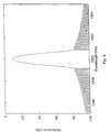
- An optical waveguide typically an optical fibre, provided with a distributed Bragg reflection grating of uniform amplitude and pitch and of low peak reflectance has a spectral reflectance characteristic of the general shape depicted in Figure 1, and has a spectral width inversely proportional to grating length.
- Figure 1 shows that the pass-band reflectance is non-uniform, and that there are side-bands of significant amplitude on both sides of the pass-band.
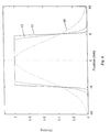
- a more uniform (flatter) pass-band can be obtained by changing from a low peak reflectance grating to a saturated grating in which peak reflectance approaches unity, as depicted in the spectral reflectance characteristic of Figure 2, but this flatter pass-band is achieved at the expense of an increase in the amplitude of the side-bands.
- the side-band level of the filter of Figure 2 can be reduced by apodisation (shading) of the grating amplitude in such a way that the strongest coupling occurs at the centre of the grating, with the coupling coefficient decaying smoothly away to a low value at each end of the grating.
- the strength of shading of such a grating will be referred to in terms of a dimensionless quantity, its normalised half-width, which for the purposes of this specification is defined as half the distance along the length of the grating over which the coupling coefficient ( ⁇ ) is at least e -1 times its maximum value ⁇ 0 , expressed as a fraction of the total length of the grating.
- Figure 3 depicts a Gaussian shading over a 5mm long grating for which the normalised shading half width is 0.2
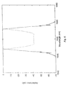
- This spectral characterisation of Figure 4 shows that the apodisation has greatly reduced the side-band amplitude of ⁇ 80dB, but left a relatively highly non-uniform amplitude pass-band.
- the spectral pass-band can be somewhat widened, and its lack of uniformity reduced, by increasing the coupling coefficient. This is shown by the comparing of the spectral reflectance characteristic of Figure 4, with that of Figure 5.
- Figure 5 is the characteristic of a filter with the same parameters as that of the filter of Figure 4, except for a twenty-fold increase of the peak coupling coefficient ⁇ 0 from 0.2 to 4mm -1 , and for a doubling of the length of the grating to 10mm, while halving the normalised half-width, so that the decay rate is identical to that of figure 4 in the central region, but does not suffer the same truncation at ⁇ 2.5mm.
- the higher coupling coefficient increased the spectral width to approximately 2nm, while the longer overall length and less severe truncation of the Gaussian apodisation reduces the level of the out of band reflectance.
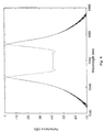
- An alternative way of providing an enlarged pass-band is to employ a chirped grating, i.e. a grating the value of whose Bragg wavelength is not constant, but is a function of position along the length of the grating.
- the Bragg wavelength at a particular position in a chirped grating is determined by its optical pitch A at that position, the optical pitch being defined as the product of the physical pitch of the grating elements at that position with the effective refractive index presented to light guided by the waveguide at that position.
- a linearly chirped grating suffers from side-bands, similar to those of an unchirped grating. These can be suppressed by apodisation, but heavily apodised uniformly chirped gratings typically exhibit significantly non-uniform spectral pass-band transmission and reflective characteristics.
- Optical waveguides provided with a distributed Bragg grating reflector having grating elements apodised to provide a coupling coefficient, ⁇ , that is a function of axial distance, z, along the waveguide, and chirped to provide an optical pitch, ⁇ , that is also a function of axial distance z, are known from each of the two articles "Fibre gratings for higher order dispersion compensation fabricated using double-scan phase-mask technique" by Williams, J.A.R., et al., Optical Fibre Communication (OFC) 1996, San Jose, Feb. 25- Mar. 1, 1996, vol.
- OFC Optical Fibre Communication
- the present invention is directed to the obtaining of filters that exhibit more uniform pass bands, good suppression of side-bands, and relatively sharp roll-off between pass-bands and side-bands.
- an optical waveguide provided with a distributed Bragg grating reflector having grating elements apodised to provide a coupling coefficient, ⁇ , that is a function of axial distance z along the waveguide, and chirped to provide an optical pitch, ⁇ , that is also a function of axial distance z, wherein the rate of change with axial distance of optical pitch is non-linear and substantially proportional to the square of the coupling coefficient.
- split-Gaussian profile a profile resulting from the insertion of a plateau at the peak of a Gaussian profile dividing that profile into two separated halves joined by the plateau.
- transition half-width a second dimensionless quantity, normalised transition half-width, which for the purposes of this specification is defined as half the difference between the length of the plateau and the length over which the coupling coefficient ⁇ is at least e -1 times its maximum (plateau) value ⁇ 0 , this difference being expressed as a fraction of the total length of the grating.
- normalised transition half-width means that the conversion of a Gaussian profile to a split-Gaussian profile by the insertion of a plateau produces a value of normalised half-transition width for the split-Gaussian profile equal to the normalised half-width of the Gaussian profile that existed prior to the insertion of the plateau).
- the normalised (Gaussian) half-width for each of the Gaussian traces 60, 61 and 62 is 0.25, and their normalised transition half-widths are respectively 0.25, 0.06 and 0.02.
- Figures 7, 8 and 9 are computed spectral reflectance and transmittance plots for linearly chirped gratings respectively having the shading profiles of traces 60, 61 and 62, the chirp being at the rate of 350 ppm/mm.
- the reflectance plot is represented by a solid line and the transmittance plot by a broken line.
- the coupling coefficient ⁇ is apodised (varied as a function of distance along the grating) in a manner to provide reduced amplitude side-bands, and in which the chirp rate varies non-linearly in direct proportion to the square of the coupling coefficient ⁇ 2 , (d ⁇ /dz ⁇ ⁇ 2 ) such a relationship being found, at least in the case of Gaussian and split-Gaussian apodisation profiles, to provide a pass-band reflectance with a high degree of flatness.
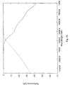
- Figures 7, 8 and 9 show the computed spectral reflectance and transmittance characteristics of three linearly chirped filters with apodisations respectively as indicated by the traces 60, 61 and 62 of Figure 6.
- Figures 10, 11 and 12 show the computed spectral reflectance and transmittance characteristics of three filters which similarly have apodisations respectively as indicated by the traces 60, 61 and 62 of Figure 6, but in this instance filters that are non-linearly chirped so that the rate of chirp varies, in each instance, in direct proportion to ⁇ 2 .
- Figure 13 shows the computed spectral reflectance and transmittance characteristics of a filter that differs from that of Figure 10 in two respects, namely that the grating length has been increased from 20 to 25mm, and the normalised half-width has been correspondingly reduced from 0.25 to 0.2. (The reduction in normalised half-width is provided so that the two filters are identical over the central 20mm; the extra 2.5mm at each end of the longer filter being used to accommodate a further reduction in amplitude of the coupling coefficient, and hence reduce the magnitude of truncation effects).
- Figure 14 shows, on a larger scale, a portion of the computed spectral reflectance and transmittance characteristics of the filter of Figure 13, illustrating its relatively rapid roll-off.
- Figure 15 shows an equivalent portion of the computed spectral reflectance and transmittance characteristics of a filter of the same length (25mm), the same peak coupling coefficient (3/mm), and the same normalised half-width (0.2), but with a linear chirp, and with a near-optimised normalised transition half-width (0.05).
- Figure 16 shows a portion of the computed spectral reflectance and transmittance characteristics of a filter providing characteristics improved somewhat over those of the filter of Figure 14 achieved by the use of a non-linearly chirped (chirp rate directly proportional to ⁇ 2 ) Gaussian apodised filter twice as long (50mm) as the filter of Figure 14, having the same normalised half-width (0.2), but a peak coupling coefficient reduced from 3.0/mm to 2.3/mm.
- This use of longer gratings with a lower peak coupling coefficient eases some fabrication issues and, in suitable circumstances, may allow high performance filters to be manufactured without recourse to hydrogen loading.
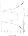
- an optical waveguide filter embodying the invention in a preferred form is constructed in a length 170 of single mode optical fibre waveguide provided with an optical core 171.
- a distributed Bragg grating the individual elements of which are schematically represented by lines 172, may be photo-induced in the fibre 170 holographically, or with the aid of a photomask.
- the grating elements may be written directly, using for instance an E-beam, UV, X-ray, or other ionising radiation.
- photo-lithography is yet another method available for grating writing.
- An apodised grating is produced by varying the strength of writing of the grating elements (and hence varying their coupling coefficients ⁇ ) as a function of distance along the fibre 170.
- An illustrative substantially Gaussian form of this variation is represented in Fibre 17B by the trace 173.
- Such variation of writing strength will typically have the ancillary effect of varying, as a function of distance along the fibre, the mean effective refractive index presented by the optical fibre to propagating light. Accordingly if the grating elements were created with a uniform pitch, the very act of producing the required apodisation will typically introduce a certain measure of chirp.
- This supplementary chirp can be provided in a number of ways. If the grating elements are individually directly written, then their physical spacing can be arranged to take the required form. Alternatively, if the grating writing employs a method that automatically produces a uniform physical pitch, then the fibre can for example be differentially strained while the elements are written, or after they have been written. Alternatively the elements can be written into fibre that has been tapered in order to provide it with a non-uniform effective refractive index. Tapering to produce the required axial profile may be achieved by taking the basic method of progressive stretching of a pair of optical fibres that is described in GB 2 150 703A for the manufacture of a tapered fused fibre coupler, and adapting it to the progressive stretching of a single fibre.
Landscapes
- Physics & Mathematics (AREA)
- General Physics & Mathematics (AREA)
- Optics & Photonics (AREA)
- Optical Integrated Circuits (AREA)
- Optical Fibers, Optical Fiber Cores, And Optical Fiber Bundles (AREA)
- Light Guides In General And Applications Therefor (AREA)
Claims (4)
- Lichtwellenleiter, der mit einem verteilten Bragg-Gitter-Reflektor versehen ist, der Gitterelemente aufweist, die apodisiert sind, um einen Kopplungskoeffizienten κ zu schaffen, der eine Funktion der axialen Strecke z entlang des Wellenleiters ist, und die gechirpt sind, um eine optische Teilung λ zu schaffen, die ebenfalls eine Funktion der axialen Strecke z ist, wobei die Änderungsrate der optischen Teilung mit der axialen Strecke nichtlinear und im wesentlichen proportional zum Quadrat des Kopplungskoeffizienten ist.
- Lichtwellenleiter nach Anspruch 1, bei dem der Lichtwellenleiter ein Lichtleitfaser-Wellenleiter ist.
- Lichtwellenleiter nach Anspruch 1, bei dem die Apodisierung der Gitterelemente im wesentlichen eine Gauß'sche Form aufweist.
- Lichtwellenleiter nach Anspruch 3, bei der Lichtwellenleiter ein Lichtleitfaser-Wellenleiter ist.
Applications Claiming Priority (3)
| Application Number | Priority Date | Filing Date | Title |
|---|---|---|---|
| US731168 | 1996-10-10 | ||
| US08/731,168 US5717799A (en) | 1996-10-10 | 1996-10-10 | Optical waveguide filters |
| PCT/GB1997/002769 WO1998015859A1 (en) | 1996-10-10 | 1997-10-08 | Optical waveguide filters |
Publications (2)
| Publication Number | Publication Date |
|---|---|
| EP0931274A1 EP0931274A1 (de) | 1999-07-28 |
| EP0931274B1 true EP0931274B1 (de) | 2001-12-19 |
Family
ID=24938348
Family Applications (1)
| Application Number | Title | Priority Date | Filing Date |
|---|---|---|---|
| EP97944968A Expired - Lifetime EP0931274B1 (de) | 1996-10-10 | 1997-10-08 | Optisches wellenleiterfilter |
Country Status (6)
| Country | Link |
|---|---|
| US (1) | US5717799A (de) |
| EP (1) | EP0931274B1 (de) |
| JP (1) | JP2001501747A (de) |
| CA (1) | CA2262681C (de) |
| DE (1) | DE69709381T2 (de) |
| WO (1) | WO1998015859A1 (de) |
Families Citing this family (18)
| Publication number | Priority date | Publication date | Assignee | Title |
|---|---|---|---|---|
| FR2745641B1 (fr) * | 1996-03-01 | 1998-04-10 | Alcatel Submarcom | Filtre obtenu par inscription d'un reseau de bragg dans une fibre optique |
| JPH09318826A (ja) * | 1996-05-24 | 1997-12-12 | Fujikura Ltd | 光導波路型フィルタおよびその製造方法 |
| US6266463B1 (en) * | 1997-06-18 | 2001-07-24 | Pirelli Cavi E Sistemi S.P.A. | Chirped optical fibre grating |
| US6115403A (en) * | 1997-07-22 | 2000-09-05 | Ciena Corporation | Directly modulated semiconductor laser having reduced chirp |
| US6108474A (en) * | 1997-12-11 | 2000-08-22 | Lucent Technologies Inc. | Optical pulse compressor for optical communications systems |
| US6694075B1 (en) | 1998-07-01 | 2004-02-17 | Corning Incorporated | Apodization of optical filters with multiple exposures of photosensitive media |
| US6362916B2 (en) * | 1998-09-25 | 2002-03-26 | Fiver Laboratories | All fiber gain flattening optical filter |
| KR100334812B1 (ko) | 1999-07-02 | 2002-05-02 | 윤종용 | 아포다이즈드 광섬유 격자 제작장치 |
| IES20000772A2 (en) * | 1999-09-23 | 2001-04-04 | Trinity College Dublin | An optical waveguide and a method for providing an optical waveguide |
| FR2800474B1 (fr) * | 1999-10-28 | 2002-01-11 | Cit Alcatel | Filtre optique a faible variation de dispersion chromatique |
| CN1100274C (zh) * | 2000-11-06 | 2003-01-29 | 清华大学 | 平坦交叉群组滤波器 |
| EP1249720A1 (de) * | 2001-04-09 | 2002-10-16 | Alcatel | Bragg-Gitter-Filter in einem optischen Wellenleiter |
| US6643429B2 (en) | 2001-06-07 | 2003-11-04 | Nortel Networks Limited | Dispersion compensation apparatus and method utilising sampled Bragg gratings |
| US6842544B2 (en) | 2001-09-14 | 2005-01-11 | E. I. Du Pont De Nemours And Company | Method for apodizing a planar waveguide grating |
| KR100484465B1 (ko) * | 2002-03-15 | 2005-04-20 | 엘지전자 주식회사 | 문자영상 출력장치 및 방법 |
| KR20050114117A (ko) * | 2004-05-31 | 2005-12-05 | 엘지전자 주식회사 | 집적광학형 실시간 지연 장치 및 그 제조 방법 |
| US7272287B2 (en) * | 2005-05-11 | 2007-09-18 | Fitel Usa Corp | Optical fiber filter for suppression of amplified spontaneous emission |
| CN100422838C (zh) * | 2005-09-08 | 2008-10-01 | 中国计量学院 | 用于光纤拉曼放大器增益平坦的啁啾布拉格光纤光栅滤波器 |
Family Cites Families (2)
| Publication number | Priority date | Publication date | Assignee | Title |
|---|---|---|---|---|
| US5058977A (en) * | 1987-01-20 | 1991-10-22 | Hewlett-Packard Company | Broadband tunable in-line filter for fiber optics |
| US5367588A (en) * | 1992-10-29 | 1994-11-22 | Her Majesty The Queen In Right Of Canada, As Represented By The Minister Of Communications | Method of fabricating Bragg gratings using a silica glass phase grating mask and mask used by same |
-
1996
- 1996-10-10 US US08/731,168 patent/US5717799A/en not_active Expired - Lifetime
-
1997
- 1997-10-08 JP JP10517315A patent/JP2001501747A/ja active Pending
- 1997-10-08 EP EP97944968A patent/EP0931274B1/de not_active Expired - Lifetime
- 1997-10-08 CA CA002262681A patent/CA2262681C/en not_active Expired - Fee Related
- 1997-10-08 WO PCT/GB1997/002769 patent/WO1998015859A1/en not_active Ceased
- 1997-10-08 DE DE69709381T patent/DE69709381T2/de not_active Expired - Fee Related
Also Published As
| Publication number | Publication date |
|---|---|
| DE69709381T2 (de) | 2002-06-20 |
| EP0931274A1 (de) | 1999-07-28 |
| WO1998015859A1 (en) | 1998-04-16 |
| JP2001501747A (ja) | 2001-02-06 |
| CA2262681A1 (en) | 1998-04-16 |
| US5717799A (en) | 1998-02-10 |
| DE69709381D1 (de) | 2002-01-31 |
| CA2262681C (en) | 2007-07-17 |
Similar Documents
| Publication | Publication Date | Title |
|---|---|---|
| EP0931274B1 (de) | Optisches wellenleiterfilter | |
| US5475780A (en) | Optical waveguiding component comprising a band-pass filter | |
| TW316953B (de) | ||
| US6005999A (en) | Waveguide narrowband rejection filter | |
| EP1032854B1 (de) | Faseroptische gitter | |
| EP0783117B1 (de) | Optische Fasern für optische Dämpfung | |
| CA2241018C (en) | Chirped optical fibre grating | |
| DE60212003T2 (de) | Gitter mit grosser Gitterperiode aufweisender optischer Bandpassfilter | |
| US20030133653A1 (en) | Optical filter and a filter method | |
| EP0831345A2 (de) | Faseroptisches Gitter | |
| US5796906A (en) | Optical planar waveguide notch filters | |
| US7095924B2 (en) | Optical filter | |
| US20100316341A1 (en) | Optical waveguide-type wavelength dispersion compensation device and manufacturing method thereof | |
| CN1387627A (zh) | 不对称低色散布拉格光栅滤光器 | |
| JP3341979B2 (ja) | 分散スロープ補償器 | |
| WO2003034116A2 (en) | Distributed gratings in optical fibres | |
| WO2001022126A1 (en) | A grating design | |
| US6947641B2 (en) | Apparatus for filtering optical radiation at an operating wavelength | |
| WO2009081904A1 (ja) | 光導波路型波長分散補償デバイスとその製造方法 | |
| JP2009151247A (ja) | 光導波路型波長分散補償デバイスとその製造方法 | |
| CA2277665C (en) | Optical waveguiding component comprising a band-pass filter | |
| Shabtay et al. | Fiber Bragg gratings as interleavers | |
| JP3452235B2 (ja) | 波長分散補償回路 | |
| Chao et al. | Design of high-performance all-fiber spectral filter with weighted coupling | |
| JP3568391B2 (ja) | 波長分散補償器 |
Legal Events
| Date | Code | Title | Description |
|---|---|---|---|
| PUAI | Public reference made under article 153(3) epc to a published international application that has entered the european phase |
Free format text: ORIGINAL CODE: 0009012 |
|
| 17P | Request for examination filed |
Effective date: 19990510 |
|
| AK | Designated contracting states |
Kind code of ref document: A1 Designated state(s): DE FR GB IT |
|
| RAP1 | Party data changed (applicant data changed or rights of an application transferred) |
Owner name: NORTEL NETWORKS LIMITED |
|
| GRAG | Despatch of communication of intention to grant |
Free format text: ORIGINAL CODE: EPIDOS AGRA |
|
| 17Q | First examination report despatched |
Effective date: 20010307 |
|
| GRAG | Despatch of communication of intention to grant |
Free format text: ORIGINAL CODE: EPIDOS AGRA |
|
| GRAH | Despatch of communication of intention to grant a patent |
Free format text: ORIGINAL CODE: EPIDOS IGRA |
|
| GRAH | Despatch of communication of intention to grant a patent |
Free format text: ORIGINAL CODE: EPIDOS IGRA |
|
| GRAA | (expected) grant |
Free format text: ORIGINAL CODE: 0009210 |
|
| AK | Designated contracting states |
Kind code of ref document: B1 Designated state(s): DE FR GB IT |
|
| REG | Reference to a national code |
Ref country code: GB Ref legal event code: IF02 |
|
| REF | Corresponds to: |
Ref document number: 69709381 Country of ref document: DE Date of ref document: 20020131 |
|
| ET | Fr: translation filed | ||
| PLBE | No opposition filed within time limit |
Free format text: ORIGINAL CODE: 0009261 |
|
| STAA | Information on the status of an ep patent application or granted ep patent |
Free format text: STATUS: NO OPPOSITION FILED WITHIN TIME LIMIT |
|
| 26N | No opposition filed | ||
| PGFP | Annual fee paid to national office [announced via postgrant information from national office to epo] |
Ref country code: GB Payment date: 20030915 Year of fee payment: 7 |
|
| PGFP | Annual fee paid to national office [announced via postgrant information from national office to epo] |
Ref country code: FR Payment date: 20031003 Year of fee payment: 7 |
|
| PGFP | Annual fee paid to national office [announced via postgrant information from national office to epo] |
Ref country code: DE Payment date: 20031031 Year of fee payment: 7 |
|
| PG25 | Lapsed in a contracting state [announced via postgrant information from national office to epo] |
Ref country code: GB Free format text: LAPSE BECAUSE OF NON-PAYMENT OF DUE FEES Effective date: 20041008 |
|
| PG25 | Lapsed in a contracting state [announced via postgrant information from national office to epo] |
Ref country code: DE Free format text: LAPSE BECAUSE OF NON-PAYMENT OF DUE FEES Effective date: 20050503 |
|
| GBPC | Gb: european patent ceased through non-payment of renewal fee |
Effective date: 20041008 |
|
| PG25 | Lapsed in a contracting state [announced via postgrant information from national office to epo] |
Ref country code: FR Free format text: LAPSE BECAUSE OF NON-PAYMENT OF DUE FEES Effective date: 20050630 |
|
| REG | Reference to a national code |
Ref country code: FR Ref legal event code: ST |
|
| PG25 | Lapsed in a contracting state [announced via postgrant information from national office to epo] |
Ref country code: IT Free format text: LAPSE BECAUSE OF NON-PAYMENT OF DUE FEES Effective date: 20051008 |