EP0933091A2 - Liquid medicine continuous infuser - Google Patents
Liquid medicine continuous infuser Download PDFInfo
- Publication number
- EP0933091A2 EP0933091A2 EP98309922A EP98309922A EP0933091A2 EP 0933091 A2 EP0933091 A2 EP 0933091A2 EP 98309922 A EP98309922 A EP 98309922A EP 98309922 A EP98309922 A EP 98309922A EP 0933091 A2 EP0933091 A2 EP 0933091A2
- Authority
- EP
- European Patent Office
- Prior art keywords
- bag
- liquid medicine
- shaped member
- elastic bag
- elastic
- Prior art date
- Legal status (The legal status is an assumption and is not a legal conclusion. Google has not performed a legal analysis and makes no representation as to the accuracy of the status listed.)
- Withdrawn
Links
Images

Classifications
-
- A—HUMAN NECESSITIES
- A61—MEDICAL OR VETERINARY SCIENCE; HYGIENE
- A61M—DEVICES FOR INTRODUCING MEDIA INTO, OR ONTO, THE BODY; DEVICES FOR TRANSDUCING BODY MEDIA OR FOR TAKING MEDIA FROM THE BODY; DEVICES FOR PRODUCING OR ENDING SLEEP OR STUPOR
- A61M5/00—Devices for bringing media into the body in a subcutaneous, intra-vascular or intramuscular way; Accessories therefor, e.g. filling or cleaning devices, arm-rests
- A61M5/14—Infusion devices, e.g. infusing by gravity; Blood infusion; Accessories therefor
- A61M5/142—Pressure infusion, e.g. using pumps
- A61M5/145—Pressure infusion, e.g. using pumps using pressurised reservoirs, e.g. pressurised by means of pistons
- A61M5/148—Pressure infusion, e.g. using pumps using pressurised reservoirs, e.g. pressurised by means of pistons flexible, e.g. independent bags
- A61M5/152—Pressure infusion, e.g. using pumps using pressurised reservoirs, e.g. pressurised by means of pistons flexible, e.g. independent bags pressurised by contraction of elastic reservoirs
-
- Y—GENERAL TAGGING OF NEW TECHNOLOGICAL DEVELOPMENTS; GENERAL TAGGING OF CROSS-SECTIONAL TECHNOLOGIES SPANNING OVER SEVERAL SECTIONS OF THE IPC; TECHNICAL SUBJECTS COVERED BY FORMER USPC CROSS-REFERENCE ART COLLECTIONS [XRACs] AND DIGESTS
- Y10—TECHNICAL SUBJECTS COVERED BY FORMER USPC
- Y10S—TECHNICAL SUBJECTS COVERED BY FORMER USPC CROSS-REFERENCE ART COLLECTIONS [XRACs] AND DIGESTS
- Y10S128/00—Surgery
- Y10S128/12—Pressure infusion
Definitions
- the present invention relates to a liquid medicine continuous infuser for giving a liquid medicine to a patient over a long time, and relates, more particularly, to a liquid medicine continuous infuser for flowing out a liquid medicine by utilizing a pressing pressure of an elastic bag (balloon).
- a liquid medicine for giving a liquid medicine to a patient such as an adult disease patient whose physical strength is exhausted greatly, there has been required the use of a liquid medication system for giving a liquid medicine to the patient by taking many hours so as to match the physical strength condition of the patient in treating the disease.
- a liquid medicine may include, for example, an anticancering drug, an anodyne, a local anesthetic, a blood sugar level adjuster, etc.
- Each of these liquid medicines is given into the body of a patient through a vein, an artery, a subcutaneous tissue, or by use of an epidural injection.
- liquid medicine continuous infuser or a fountain syringe for continuously flowing out a liquid medicine by utilizing the pressing pressure of a balloon
- This liquid medicine continuous infuser comprises a cylindrical external axis, an internal axis slidably accommodated within this external axis and a cylindrical balloon with its both ends fixed air-tight at an outer periphery of these axes, and a flow rate controller, a tube, a liquid medicine injecting needle, etc. are connected sequentially to an opening of the external axis through a three-directional stop cock,
- a liquid medicine to be given to a patient is filled into the balloon through the three-directional stop cock, the external axis and a gap between the external axis and the internal axis. Then, the liquid medicine is passed through the flow rate controller, the tube, the adapter, etc. after having been switched over by the three-directional stop cock, and finally the liquid medicine is given to the patient from through a vein or other route by a liquid medicine injecting needle.
- the internal axis is projected from the external axis along with the charging of the liquid medicine, and thus the capacity of the balloon can be made larger by inflating the balloon not only in a radial direction but also in an axial direction. Also, at the time of finishing the medication of the liquid medicine, the internal axis is accommodated within the external axis and the balloon is contracted into an axial direction, so that a remaining volume of the liquid medicine can be made smaller.
- the volume of the liquid medicine remaining in the liquid medicine continuous infuser after finishing the medication is as small as possible from the viewpoint of ensuring a secure medication and avoiding an occurrence of an unused liquid medicine.
- the liquid medicine continuous infuser having the above-described structure cannot meet the above requirement satisfactorily, and thus it has been desired to provide a novel liquid medicine continuous infuser that can effectively reduce the volume of the liquid medicine remaining in the infuser after finishing a medication.
- the inventor of the present invention has carried out various investigations by using the liquid medicine continuous infuser as disclosed in Japanese Patent Application Laid-Open No. 64-70069 and has found that this infuser has the following characteristics.
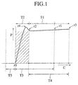
- Fig. 1 is a characteristic diagram for showing a relationship between a capacity C of the balloon of the liquid medicine continuous infuser and a contraction pressure P of the balloon, where the horizontal axis shows a capacity level of the balloon and the vertical axis shows a contraction pressure.
- the contraction pressure increases suddenly from a free state (r0) where the contraction pressure is zero (0), then the contraction pressure reaches a peak of a maximum value (r4) and decreases once thereafter to take a minimum value (r2) as shown in a range T2.
- This fact corresponds to a fact that every one can experience at the time of inflating a rubber balloon.
- this fact corresponds to a fact that it initially requires relatively large power to expand the film of the balloon as the balloon near to its free state maintains almost an intrinsic film thickness of the balloon. Then, after this state, it does not require so much large power to further expand the film of the balloon as the film thickness is small once the balloon has been inflated to a certain level.
- a liquid medicine is charged into the balloon to inflate the balloon so as to reach a predetermined balloon capacity (r1) larger than the capacity of the balloon corresponding to the peak (r4) of the contraction pressure as shown in a range T3, and thereafter, the balloon is made to shrivel to a free state where the contraction pressure is zero (r0), during period which the liquid medicine is flowed out.
- the liquid medicine outflow has to pass through an area of the range T2 where the contraction pressure changes suddenly, so that the flow rate of the outflowing liquid medicine is lowered suddenly when approaching the free state (r0). This is considered a factor that makes it difficult to maintain a practically constant outflow level of the liquid medicine and that becomes an obstacle to an elimination of the remaining liquid medicine as well.
- a liquid medicine continuous infuser according to the present invention has been made based on the above-described results of the investigations, and the infuser has a basic structure comprising a bag-shaped member that can apply a pressure to a liquid medicine accommodated inside the infuser, an inflow/outflow section for flowing in and flowing out the liquid medicine, and an area positioned inside the bag-shaped member and having a predetermined volume.
- the above pressure provides a predetermined characteristic curve in relation to the capacity of the bag-shaped member, and the area having the predetermined volume is for increasing the capacity of the bag-shaped member when the liquid medicine is accommodated inside the bag-shaped member.
- the bag- shaped member is for applying a pressure to a liquid medicine accommodated inside the bag-shaped member along with a predetermined characteristic curve, with a pressure, corresponding to the capacity increased by the area having the predetermined volume when the liquid medicine has been accommodated inside the bag-shaped member used, as an initial value.
- the liquid medicine continuous infuser according to the present invention has an inner bag into which a liquid medicine is to be charged, and the inner bag can be disposed inside the bag-shaped member.
- the bag-shaped member is an elastic bag and that the area positioned inside the bag-shaped member and having a predetermined volume is formed by a fluid disposed between the elastic bag and the inner bag.
- the section of T1 in Fig. 1 can be set longer and the flow rate of the outflowing liquid medicine can be made constant.
- the sum of the volume of the fluid and the volume of the inner bag when the inner bag is shriveled completely is larger than the capacity of the elastic bag in its free state, in order to reduce the remaining volume of the liquid medicine more securely and to further stabilize the flow rate of the outflowing liquid medicine.
- the bag-shaped member is an elastic bag and that the area positioned inside the bag-shaped member and having a predetermined volume is formed by a core disposed inside the elastic bag.
- the pressing pressure of the elastic bag will not decrease suddenly, as the elastic bag is in a state inflated by the core even if the elastic bag approaches its free state and there remains almost no volume of the liquid medicine.
- the volume of the core is larger than the capacity of the elastic bag in its free state, for the purpose of reducing the remaining volume of the liquid medicine more securely and for more stabilizing the flow rate of the outflowing liquid medicine.
- the liquid medicine continuous infuser according to the present invention can also take such a structure that the bag-shaped member is an elastic bag and this elastic bag has a pair of mutually opposite flat surfaces and a peripheral wall for connecting the pair of flat surfaces, thus forming a flat bag shape as a whole, and the thickness of each of the pair of flat surfaces is larger than the thickness of the peripheral wall at least at a center portion of each of the pair of flat surfaces.
- each of the pair of flat surfaces gradually decreases in the vicinity of a portion where the flat surfaces are connected to the peripheral wall from the viewpoint of achieving a more flat shape as a whole.
- the liquid medicine continuous infuser according to the present invention can also take such a structure that the bag-shaped member is an elastic bag and this elastic bag has a pair of mutually opposite flat surfaces and a peripheral wall for connecting the pair of flat surfaces, thus forming a flat bag shape as a whole, and there may be provided a panel member having a higher stiffness than that of the elastic bag on the pair of flat surfaces.
- the inflow/outflow section is an inflow/outflow opening provided corresponding to the peripheral wall of the elastic bag, for achieving a flat shape as a whole and for facilitating a user to carry the infuser, when it is placed in a pocket or an accessory case, by facing the outflow opening to an opening of the pocket. This also achieves a secure inflow/outflow of the liquid medicine.
- Figs. 2A to 2D show states of a liquid medicine continuous infuser charged with a liquid medicine
- Fig. 2A is a side cross-sectional view
- Fig. 2B is a cross-sectional view cut along an A-A line of Fig. 2A
- Fig. 2C is a cross-sectional view cut along a B-B line of Fig. 2B
- Fig. 2D is a partially enlarged cross-sectional view of Fig. 2A
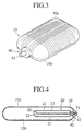
- Fig. 3 is a perspective view for showing an appearance of the liquid medicine continuous infuser
- Fig. 4 is a side cross-sectional view for showing a state of the liquid medicine continuous infuser with the liquid medicine flowed out completely.
- the liquid medicine continuous infuser of the present embodiment has a protection case 10 made of a synthetic resin, a metal and the like to form a flat pillow shape as a whole.
- a liquid inflow/outflow opening 40 having its opening 42 stretched to the outside.
- the protection case 10 is structured by two members of an upper member 10a and a lower member 10b which can be opened or closed by hinges not shown and can be fixed in a closed state by a stopper not shown.
- an elastic bag 20 made of an elastic material such as a natural rubber or a synthetic rubber to form a flat bag shape as a whole.
- 21 denotes a pair of flat surfaces of the elastic bag 20
- 22 denotes a peripheral wall for connecting the pair of flat surfaces 21.
- an inner bag 30 to be filled with a liquid medicine 31.
- a bag of an elastic material similar to that of the elastic bag 20 is preferably employed for the inner bag 30.
- This bag may also be the one formed by a synthetic resin film or a synthetic resin film laminated by a metal foil or the like.
- the inner bag 30 is formed to have the content capacity of the state that the liquid medicine 31 is filled to the full.
- a natural rubber or a synthetic rubber is used for the inner bag 30, it is desirable to have a chemical resistant film such as a silicon rubber or the like formed on the inner surface of the inner bag so as to prevent an additive or the like in the rubber from being solved into the liquid medicine 31.
- the liquid medicine inflow/outflow opening 40 projecting from the end of the protection case 10 is formed by a tubular member in the present embodiment, and this tubular member pierces through an end part formed on the peripheral wall 22 of the elastic bag 20, is connected to an end of the inner bag 30 and is introduced into the inner bag 30.
- the elastic bag 20 is connected air-tight to an outer periphery of the liquid medicine inflow/outflow opening 40.
- a check valve 41 is disposed within the liquid medicine inflow/ outflow opening 40.
- the check valve 41 has a structure like an air injection opening of a tire of an automobile, for example, and a valve of the check valve 41 opens at the time of injecting the liquid medicine into the inside from the outside and closes when the liquid medicine tries to outflow from the inside.
- a pipe-shaped injection port connected to a medication tube or the like is inserted into the check valve from the outside to cancel the check, so that the valve is opened compulsively to flow out the liquid medicine 31.
- the elastic bag 20 is structured to give a pressing pressure to the outer periphery of the inner bag 30 even in the state that the inner bag 30 is not filled with the liquid medicine 31.
- the content capacity of the elastic bag 20 is set to the state of r2 in Fig. 1 by the volume of the inner bag 30 and the fluid 23 even in the state that the liquid medicine 31 is not filled in the inner bag 30.
- a three-directional stop cock capable of switching the passage of the liquid medicine 31, instead of the check valve 41.
- a syringe for injecting a liquid medicine and a medication tube are connected to the three-directional stop cock, then the liquid medicine is filled into the inner bag 30 from the syringe through the three-directional stop cock, a passage of the three-directional stop cock is opened at the medication tube side, and the liquid medicine inside the inner bag 30 is sent to the medication tube for achieving the medication.
- the liquid medicine inflow/outflow opening 40 may also be the one separately provided with a liquid medicine inflow opening and a liquid medicine outflow opening.
- the liquid medicine inflow opening may be provided with a check valve to enable a liquid medicine to be filled into the inner bag 30 by use of the syringe or the like and the liquid medicine outflow opening may be provided with a normal valve unit to open the valve unit at the time of medication.
- the liquid medicine inflow/outflow opening 40 is connected with a medication needle through a flow rate control valve, a filter, a medication tube, etc., but not shown.
- the medication needle is inserted into a vein or other part of a patient to start a medication of the liquid medicine.
- a syringe such as a hypodermic syringe or the like not shown is connected to the opening 42 of the liquid medicine inflow /outflow opening 40 by inserting the syringe into this opening, and the liquid medicine 31 to be given to a patient is injected into the liquid medicine inflow/outflow opening 40 by the syringe or the like. Then, the check valve 41 inside the liquid medicine inflow/outflow opening 40 is opened and the liquid medicine 31 is filled into the inner bag 30.
- the elastic bag 20 is inflated to the full inside the protection case 10. Therefore, the elastic bag 20 is inflated along the inner peripheral shape of the protection case 10. Since the protection case 10 has a flat shape, this is easily portable in the pocket or others.
- a pipe-shaped injection opening provided at an end of a medication tube not shown is inserted into the liquid medicine inflow/outflow opening 40, and the medication tube is connected to the liquid medicine inflow/outflow opening 40.
- the check valve 41 is opened compulsively by the pipe-shaped injection opening.
- the liquid medicine 31 inside the inner bag 30 flows out to the medication tube through the liquid medicine inflow/outflow opening 40, and the liquid medicine 31 is given to the patient through his or her vein or other part from the medication needle not shown connected to a front end of the medication tube.
- the content capacity of the elastic bag 20 is set to the state of r2 in Fig. 1 by the volume of the inner bag 30 and the fluid 23 even in the state that the liquid medicine 31 is not filled in the inner bag 30.
- the content capacity of the elastic bag 20 becomes the state of r3 in Fig. 1.
- the content volume of the elastic bag 20 changes from the state of r3 to r2 as shown in the section of T4 in Fig. 1 along with the outflow of the liquid medicine 31.
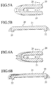
- Figs. 5A and 5B show one example of a shape of the elastic bag 20 that can be suitably applied to the liquid medicine continuous infuser of the present embodiment.
- Fig. 5A is a partial lateral cross-sectional view of the elastic bag 20 and
- Fig. 5B is a cross-sectional view cut along a C-C line of Fig. 5A.
- This elastic bag 20 has a flat bag shape as a whole, with the thickness of each of the mutually opposite flat surfaces 21 larger than the thickness of the peripheral wall 22. Accordingly, when a liquid medicine is filled into the inner bag 30, the elastic bag 20 is inflated with the peripheral wall 22 expanded greatly as shown by arrows in the drawing, so that the elastic bag 20 is easily expandable by keeping a flat shape as a whole. As a result, it is possible to inflate the elastic bag 20 in a shape to match more suitably with the inner peripheral shape of the protection case 10.
- Figs. 6A and 6B show another example of a shape of the elastic bag 20 that can be suitably applied to the liquid medicine continuous infuser of the present embodiment.
- Fig. 6A is a partial lateral cross-sectional view of the elastic bag 20 and
- Fig. 6B is a cross-sectional view cut along a D-D line of Fig. 6A.
- This elastic bag 20 has a flat bag shape as a whole, with the thickness of each of the mutually opposite flat surfaces 21 set gradually smaller at a peripheral edge portion and with the thickness of the peripheral wall 22 also set small. Accordingly, when a liquid medicine is filled into the inner bag 30, the elastic bag 20 is inflated with the peripheral wall 22 expanded greatly as shown by arrows in the drawings, so that the elastic bag 20 is easily expandable by keeping a flat shape as a whole. As a result, it is possible to inflate the elastic bag 20 in a shape to match more suitably with the inner peripheral shape of the protection case 10.
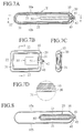
- Figs. 7A to 7D show a state of the liquid medicine continuous infuser filled with a liquid medicine
- Fig. 7A is a side cross-sectional view
- Fig. 7B is a cross-sectional view cut along an E-E line of Fig. 7A
- Fig. 7C is a cross-sectional view cut along an F-F line of Fig. 7B
- Fig. 7D is an enlarged cross-sectional view of a Y portion of Fig. 7A
- Fig. 8 is a side cross-sectional view for showing a state of the liquid medicine continuous infuser with the liquid medicine flowed out completely.
- Those portions practically identical with portions of the first embodiment are attached with the same reference symbols by omitting a detailed explanation thereof.
- a liquid medicine is filled directly into an elastic bag 20.
- a cylindrical liquid medicine inflow/outflow opening 40 is integrally formed with one end of a peripheral wall 22 in the longitudinal direction of the elastic bag 20. This liquid medicine inflow/outflow opening 40 is stretched to the outside from one end of a protection case 10 in its longitudinal direction.
- a check valve 41 is provided within the liquid medicine inflow/outflow opening 40.
- the present embodiment is characterized in that there is inserted into the elastic bag 20 a core 50 having a larger volume than a content capacity of the elastic bag 20 in its free state.
- a core 50 it is possible to use a solid unit body made of a synthetic resin or a metal, or a bag member filled with a gas, a liquid or the like.
- the inside of this core can be hollowed to reduce the weight.
- the core 50 has a shape easily adaptable to an inner peripheral shape of the elastic bag 20 when the elastic bag 20 is shriveled. Further, there may be provided with a recess 51 or the like at an end of the core 50 in order to prevent the liquid medicine inflow/outflow opening 40 from being closed by the core 50.
- the content capacity of the elastic bag 20 is set to the state of r2 in Fig. 1 by the volume of the core 50 even in the state that a liquid medicine 31 is not filled in the elastic bag 20.
- the content capacity of the elastic bag 20 becomes the state of r3 in Fig. 1.
- the content capacity of the elastic bag 20 changes from the state of r3 to r2 as shown in the section of T4 in Fig. 1 along with the outflow of the liquid medicine 31.
- the elastic bag 20 may also be structured by use of double bags, formed of an inner bag to be filled with the liquid medicine 31 and an external bag of an elastic material for applying a pressing pressure to the liquid medicine 31.
- the inner bag and the external bag may be integrally laminated to form a bag of a double-layer structure.
- the elastic bag shown in Figs. 5A and 5B or Figs. 6A and 6B as explained in the first embodiment.
- the elastic bag provided with a highly stiff panel on the flat surface of the elastic bag it is also possible to employ the elastic bag provided with a highly stiff panel on the flat surface of the elastic bag.
Landscapes
- Health & Medical Sciences (AREA)
- Hematology (AREA)
- Engineering & Computer Science (AREA)
- Anesthesiology (AREA)
- Biomedical Technology (AREA)
- Heart & Thoracic Surgery (AREA)
- Vascular Medicine (AREA)
- Life Sciences & Earth Sciences (AREA)
- Animal Behavior & Ethology (AREA)
- General Health & Medical Sciences (AREA)
- Public Health (AREA)
- Veterinary Medicine (AREA)
- Infusion, Injection, And Reservoir Apparatuses (AREA)
- Medical Preparation Storing Or Oral Administration Devices (AREA)
Abstract
Description
- The present invention relates to a liquid medicine continuous infuser for giving a liquid medicine to a patient over a long time, and relates, more particularly, to a liquid medicine continuous infuser for flowing out a liquid medicine by utilizing a pressing pressure of an elastic bag (balloon).
- For giving a liquid medicine to a patient such as an adult disease patient whose physical strength is exhausted greatly, there has been required the use of a liquid medication system for giving a liquid medicine to the patient by taking many hours so as to match the physical strength condition of the patient in treating the disease. Such a liquid medicine may include, for example, an anticancering drug, an anodyne, a local anesthetic, a blood sugar level adjuster, etc. Each of these liquid medicines is given into the body of a patient through a vein, an artery, a subcutaneous tissue, or by use of an epidural injection.
- As one of such liquid medication systems, there has been disclosed a liquid medicine continuous infuser or a fountain syringe for continuously flowing out a liquid medicine by utilizing the pressing pressure of a balloon, as disclosed in Japanese Patent Application Laid-Open No. 64-70069. This liquid medicine continuous infuser comprises a cylindrical external axis, an internal axis slidably accommodated within this external axis and a cylindrical balloon with its both ends fixed air-tight at an outer periphery of these axes, and a flow rate controller, a tube, a liquid medicine injecting needle, etc. are connected sequentially to an opening of the external axis through a three-directional stop cock,
- A liquid medicine to be given to a patient is filled into the balloon through the three-directional stop cock, the external axis and a gap between the external axis and the internal axis. Then, the liquid medicine is passed through the flow rate controller, the tube, the adapter, etc. after having been switched over by the three-directional stop cock, and finally the liquid medicine is given to the patient from through a vein or other route by a liquid medicine injecting needle. At the time of charging the liquid medicine into the balloon, the internal axis is projected from the external axis along with the charging of the liquid medicine, and thus the capacity of the balloon can be made larger by inflating the balloon not only in a radial direction but also in an axial direction. Also, at the time of finishing the medication of the liquid medicine, the internal axis is accommodated within the external axis and the balloon is contracted into an axial direction, so that a remaining volume of the liquid medicine can be made smaller.
- It is desirable that the volume of the liquid medicine remaining in the liquid medicine continuous infuser after finishing the medication is as small as possible from the viewpoint of ensuring a secure medication and avoiding an occurrence of an unused liquid medicine. However, the liquid medicine continuous infuser having the above-described structure cannot meet the above requirement satisfactorily, and thus it has been desired to provide a novel liquid medicine continuous infuser that can effectively reduce the volume of the liquid medicine remaining in the infuser after finishing a medication.
- Further, from the viewpoint of achieving a proper medication, it has also been desired to provide a liquid medicine continuous infuser that can maintain a substantially constant level of a liquid medicine that is given to a patient without a sudden variation in the volume of the liquid medicine during the medication.
- It is an object of the present invention to provide a liquid medicine continuous infuser that can effectively flow out a liquid medicine by keeping a stable outflow level to the last moment and that can reduce the volume of the liquid medicine remaining in the infuser to an extremely low level at the time of finishing the medication.
- In an attempt to achieve the above object, the inventor of the present invention has carried out various investigations by using the liquid medicine continuous infuser as disclosed in Japanese Patent Application Laid-Open No. 64-70069 and has found that this infuser has the following characteristics.
- Fig. 1 is a characteristic diagram for showing a relationship between a capacity C of the balloon of the liquid medicine continuous infuser and a contraction pressure P of the balloon, where the horizontal axis shows a capacity level of the balloon and the vertical axis shows a contraction pressure. In this diagram, when the capacity of the balloon increases, the contraction pressure increases suddenly from a free state (r0) where the contraction pressure is zero (0), then the contraction pressure reaches a peak of a maximum value (r4) and decreases once thereafter to take a minimum value (r2) as shown in a range T2.
- Then, when the balloon capacity increases further, the contraction pressure increases gradually as shown in a range T1.
- This fact corresponds to a fact that every one can experience at the time of inflating a rubber balloon. In other words, this fact corresponds to a fact that it initially requires relatively large power to expand the film of the balloon as the balloon near to its free state maintains almost an intrinsic film thickness of the balloon. Then, after this state, it does not require so much large power to further expand the film of the balloon as the film thickness is small once the balloon has been inflated to a certain level.
- According to a further investigation by the inventor, it has been made clear that in the liquid medicine continuous infuser having the above-described characteristics, a liquid medicine is charged into the balloon to inflate the balloon so as to reach a predetermined balloon capacity (r1) larger than the capacity of the balloon corresponding to the peak (r4) of the contraction pressure as shown in a range T3, and thereafter, the balloon is made to shrivel to a free state where the contraction pressure is zero (r0), during period which the liquid medicine is flowed out.
- Accordingly, it can be concluded that, according to the conventional liquid medicine continuous infuser that is used in the above-described manner, a liquid medicine of the volume corresponding to the balloon capacity shown in a range T5 is left in the balloon so that the whole volume of the liquid medicine cannot be flowed out, as the internal space of the balloon does not disappear completely even if the balloon has shriveled to become the free state (r0).
- Further, in the above using state, the liquid medicine outflow has to pass through an area of the range T2 where the contraction pressure changes suddenly, so that the flow rate of the outflowing liquid medicine is lowered suddenly when approaching the free state (r0). This is considered a factor that makes it difficult to maintain a practically constant outflow level of the liquid medicine and that becomes an obstacle to an elimination of the remaining liquid medicine as well.
- A liquid medicine continuous infuser according to the present invention has been made based on the above-described results of the investigations, and the infuser has a basic structure comprising a bag-shaped member that can apply a pressure to a liquid medicine accommodated inside the infuser, an inflow/outflow section for flowing in and flowing out the liquid medicine, and an area positioned inside the bag-shaped member and having a predetermined volume.
- The above pressure provides a predetermined characteristic curve in relation to the capacity of the bag-shaped member, and the area having the predetermined volume is for increasing the capacity of the bag-shaped member when the liquid medicine is accommodated inside the bag-shaped member.
- Further, the bag- shaped member is for applying a pressure to a liquid medicine accommodated inside the bag-shaped member along with a predetermined characteristic curve, with a pressure, corresponding to the capacity increased by the area having the predetermined volume when the liquid medicine has been accommodated inside the bag-shaped member used, as an initial value.
- With the above-described structure, it is possible to provide a liquid medicine continuous infuser that can effectively flow out a liquid medicine at a stable outflow rate to the last moment and that can reduce the remaining volume of the liquid medicine to an extremely low level at the time of fishing its medication.
- More specifically, the liquid medicine continuous infuser according to the present invention has an inner bag into which a liquid medicine is to be charged, and the inner bag can be disposed inside the bag-shaped member. In this case, it is preferable that the bag-shaped member is an elastic bag and that the area positioned inside the bag-shaped member and having a predetermined volume is formed by a fluid disposed between the elastic bag and the inner bag.
- Based on the above structure, it becomes possible to effectively reduce the remaining volume of the liquid medicine, as the inner bag is pressed to be shriveled by a volume corresponding to the volume of the fluid even if the elastic bag becomes a free state. Further, based on the existence of the fluid, the section of T1 in Fig. 1 can be set longer and the flow rate of the outflowing liquid medicine can be made constant.
- In this case, it is more preferable that the sum of the volume of the fluid and the volume of the inner bag when the inner bag is shriveled completely is larger than the capacity of the elastic bag in its free state, in order to reduce the remaining volume of the liquid medicine more securely and to further stabilize the flow rate of the outflowing liquid medicine.
- On the other hand, more specifically, it is also possible to have such a structure that the bag-shaped member is an elastic bag and that the area positioned inside the bag-shaped member and having a predetermined volume is formed by a core disposed inside the elastic bag.
- Based on the above structure, the pressing pressure of the elastic bag will not decrease suddenly, as the elastic bag is in a state inflated by the core even if the elastic bag approaches its free state and there remains almost no volume of the liquid medicine. In other words, it is possible to apply a practically constant pressing pressure to a liquid medicine during a period from the start to the finish of the medication, so that the flow rate of the outflowing liquid medicine can be made practically constant and almost all the volume of the liquid medicine within the elastic bag can be flowed out, thereby effectively preventing an occurrence of a remaining of the liquid medicine.
- In this case, it is more preferable that the volume of the core is larger than the capacity of the elastic bag in its free state, for the purpose of reducing the remaining volume of the liquid medicine more securely and for more stabilizing the flow rate of the outflowing liquid medicine.
- Further, the liquid medicine continuous infuser according to the present invention can also take such a structure that the bag-shaped member is an elastic bag and this elastic bag has a pair of mutually opposite flat surfaces and a peripheral wall for connecting the pair of flat surfaces, thus forming a flat bag shape as a whole, and the thickness of each of the pair of flat surfaces is larger than the thickness of the peripheral wall at least at a center portion of each of the pair of flat surfaces.
- Based on the above structure, it is possible to provide a liquid medicine continuous infuser having a flat shape as a whole when a liquid medicine is filled into the infuser as mainly the peripheral wall is deformed, so that a user can carry the infuser in his or her pocket or an accessory case.
- In this case, it is preferable that the thickness of each of the pair of flat surfaces gradually decreases in the vicinity of a portion where the flat surfaces are connected to the peripheral wall from the viewpoint of achieving a more flat shape as a whole.
- Further, the liquid medicine continuous infuser according to the present invention can also take such a structure that the bag-shaped member is an elastic bag and this elastic bag has a pair of mutually opposite flat surfaces and a peripheral wall for connecting the pair of flat surfaces, thus forming a flat bag shape as a whole, and there may be provided a panel member having a higher stiffness than that of the elastic bag on the pair of flat surfaces.
- Based on the above structure, it is possible to provide an easily portable liquid medicine continuous infuser having a flat shape as a whole when a liquid medicine is filled into the infuser, as the panel member restricts an inflating of the flat surfaces.
- In the liquid medicine continuous infuser of the present invention, it is preferable that the inflow/outflow section is an inflow/outflow opening provided corresponding to the peripheral wall of the elastic bag, for achieving a flat shape as a whole and for facilitating a user to carry the infuser, when it is placed in a pocket or an accessory case, by facing the outflow opening to an opening of the pocket. This also achieves a secure inflow/outflow of the liquid medicine.
-
- Fig. 1 is a characteristic diagram for showing a relationship between a capacity C and a contraction pressure P of a liquid medicine continuous infuser.
- Fig. 2A is aside cross-sectional view for showing a state of a liquid medicine continuous infuser charged with a liquid medicine according to a first embodiment of the present invention.
- Fig. 2B is a cross-sectional view cut along an A-A line of Fig. 2A.
- Fig. 2C is a cross-sectional view cut along a B-B line of Fig. 2B.
- Fig. 2D is an enlarged cross-sectional view of an X portion of Fig. 2A.
- Fig. 3 is a perspective view for showing an appearance of the liquid medicine continuous infuser of the same embodiment.
- Fig. 4 is a side cross-sectional view for showing a state of the liquid medicine continuous infuser with the liquid medicine flowed out completely in the same embodiment.
- Fig. 5A is a partial lateral cross-sectional view for showing one example of an elastic bag of the liquid medicine continuous infuser of the same embodiment.
- Fig. 5B is a cross-sectional view cut along a C-C line of Fig. 5A.
- Fig. 6A is a partial lateral cross-sectional view for showing another example of an elastic bag of the liquid medicine continuous infuser of the same embodiment.
- Fig. 6B is a cross-sectional view cut along a D-D line of Fig. 6A.
- Fig. 7A is aside cross-sectional view for showing a state of a liquid medicine continuous infuser charged with a liquid medicine according to a second embodiment of the present invention.
- Fig. 7B is a cross-sectional view cut along an E-E line of Fig. 7A.
- Fig. 7C is a cross-sectional view cut along an F-F line of Fig. 7B.
- Fig. 7D is an enlarged cross-sectional view of a Y portion of Fig. 7A.
- Fig. 8 is a side cross-sectional view for showing a state of the liquid medicine continuous infuser with the liquid medicine flowed out completely in the same embodiment.
-
- Each of embodiments of the present invention will be explained in detail below with reference to the drawings.
- At first, a first embodiment of a liquid medicine continuous infuser of the present invention will be explained mainly with reference to Figs. 2A to 4.
- Figs. 2A to 2D show states of a liquid medicine continuous infuser charged with a liquid medicine; Fig. 2A is a side cross-sectional view, Fig. 2B is a cross-sectional view cut along an A-A line of Fig. 2A, Fig. 2C is a cross-sectional view cut along a B-B line of Fig. 2B, Fig. 2D is a partially enlarged cross-sectional view of Fig. 2A, Fig. 3 is a perspective view for showing an appearance of the liquid medicine continuous infuser, and Fig. 4 is a side cross-sectional view for showing a state of the liquid medicine continuous infuser with the liquid medicine flowed out completely.
- The liquid medicine continuous infuser of the present embodiment has a
protection case 10 made of a synthetic resin, a metal and the like to form a flat pillow shape as a whole. At an end, in a longitudinal direction, of theprotection case 10, there is provided a liquid inflow/outflow opening 40 having itsopening 42 stretched to the outside. Theprotection case 10 is structured by two members of anupper member 10a and alower member 10b which can be opened or closed by hinges not shown and can be fixed in a closed state by a stopper not shown. - Within the
protection case 10, there is disposed anelastic bag 20 made of an elastic material such as a natural rubber or a synthetic rubber to form a flat bag shape as a whole. In the drawings, 21 denotes a pair of flat surfaces of theelastic bag flat surfaces 21. Further, inside theelastic bag 20, there is disposed aninner bag 30 to be filled with aliquid medicine 31. A bag of an elastic material similar to that of theelastic bag 20 is preferably employed for theinner bag 30. This bag may also be the one formed by a synthetic resin film or a synthetic resin film laminated by a metal foil or the like. However, when a synthetic resin film having no elasticity is used, theinner bag 30 is formed to have the content capacity of the state that theliquid medicine 31 is filled to the full. When a natural rubber or a synthetic rubber is used for theinner bag 30, it is desirable to have a chemical resistant film such as a silicon rubber or the like formed on the inner surface of the inner bag so as to prevent an additive or the like in the rubber from being solved into theliquid medicine 31. - The liquid medicine inflow/
outflow opening 40 projecting from the end of theprotection case 10 is formed by a tubular member in the present embodiment, and this tubular member pierces through an end part formed on theperipheral wall 22 of theelastic bag 20, is connected to an end of theinner bag 30 and is introduced into theinner bag 30. Theelastic bag 20 is connected air-tight to an outer periphery of the liquid medicine inflow/outflow opening 40. Acheck valve 41 is disposed within the liquid medicine inflow/outflow opening 40. Thecheck valve 41 has a structure like an air injection opening of a tire of an automobile, for example, and a valve of thecheck valve 41 opens at the time of injecting the liquid medicine into the inside from the outside and closes when the liquid medicine tries to outflow from the inside. At the time of medicating theliquid medicine 31 to a patient, a pipe-shaped injection port connected to a medication tube or the like is inserted into the check valve from the outside to cancel the check, so that the valve is opened compulsively to flow out theliquid medicine 31. - Further, in the present embodiment, there is sealed a fluid 23 prepared from a liquid such as water and a gas such as air into a gap between the
elastic bag 20 and theinner bag 30. The sum of the volume of the fluid 23 and the volume of theinner bag 30 when it is shriveled completely is made larger than the content capacity of theelastic bag 20 in its free state. As a result, theelastic bag 20 is structured to give a pressing pressure to the outer periphery of theinner bag 30 even in the state that theinner bag 30 is not filled with theliquid medicine 31. In the case of the present embodiment, the content capacity of theelastic bag 20 is set to the state of r2 in Fig. 1 by the volume of theinner bag 30 and the fluid 23 even in the state that theliquid medicine 31 is not filled in theinner bag 30. - In the liquid medicine inflow/
outflow opening 40, there may be provided a three-directional stop cock capable of switching the passage of theliquid medicine 31, instead of thecheck valve 41. In other words, it is possible to arrange such that a syringe for injecting a liquid medicine and a medication tube are connected to the three-directional stop cock, then the liquid medicine is filled into theinner bag 30 from the syringe through the three-directional stop cock, a passage of the three-directional stop cock is opened at the medication tube side, and the liquid medicine inside theinner bag 30 is sent to the medication tube for achieving the medication. - As the liquid medicine inflow/
outflow opening 40, this may also be the one separately provided with a liquid medicine inflow opening and a liquid medicine outflow opening. In this case, the liquid medicine inflow opening may be provided with a check valve to enable a liquid medicine to be filled into theinner bag 30 by use of the syringe or the like and the liquid medicine outflow opening may be provided with a normal valve unit to open the valve unit at the time of medication. - Further, the liquid medicine inflow/
outflow opening 40 is connected with a medication needle through a flow rate control valve, a filter, a medication tube, etc., but not shown. The medication needle is inserted into a vein or other part of a patient to start a medication of the liquid medicine. The above-described structures are known from the disclosure in Japanese Patent Application Laid-Open No. 64-7006 or others, and their explanation will be omitted here. - There will be explained below the operation of the liquid medicine continuous infuser according to the present embodiment at the time of medicating a liquid medicine after the medicine has been filled in the infuser.
- In preparation, a syringe such as a hypodermic syringe or the like not shown is connected to the
opening 42 of the liquid medicine inflow /outflow opening 40 by inserting the syringe into this opening, and theliquid medicine 31 to be given to a patient is injected into the liquid medicine inflow/outflow opening 40 by the syringe or the like. Then, thecheck valve 41 inside the liquid medicine inflow/outflow opening 40 is opened and theliquid medicine 31 is filled into theinner bag 30. When theliquid medicine 31 has been filled into theinner bag 30 to the full, theelastic bag 20 is inflated to the full inside theprotection case 10. Therefore, theelastic bag 20 is inflated along the inner peripheral shape of theprotection case 10. Since theprotection case 10 has a flat shape, this is easily portable in the pocket or others. - In this state, a pipe-shaped injection opening provided at an end of a medication tube not shown is inserted into the liquid medicine inflow/
outflow opening 40, and the medication tube is connected to the liquid medicine inflow/outflow opening 40. Then, thecheck valve 41 is opened compulsively by the pipe-shaped injection opening. As a result, theliquid medicine 31 inside theinner bag 30 flows out to the medication tube through the liquid medicine inflow/outflow opening 40, and theliquid medicine 31 is given to the patient through his or her vein or other part from the medication needle not shown connected to a front end of the medication tube. - In this case, the content capacity of the
elastic bag 20 is set to the state of r2 in Fig. 1 by the volume of theinner bag 30 and the fluid 23 even in the state that theliquid medicine 31 is not filled in theinner bag 30. When theliquid medicine 31 is filled into theinner bag 30, the content capacity of theelastic bag 20 becomes the state of r3 in Fig. 1. Once the medication of theliquid medicine 31 is started, the content volume of theelastic bag 20 changes from the state of r3 to r2 as shown in the section of T4 in Fig. 1 along with the outflow of theliquid medicine 31. - As there is almost no change in the contraction pressure of the
elastic bag 20 during the section shown by T4, it is possible to apply almost a constant pressing pressure to theinner bag 30 from the beginning to the end of the medication. As a result, it is possible to make theliquid medicine 31 outflow at almost a constant flow rate from the beginning to the end of the medication. Even if there is left almost noliquid medicine 31 within theinner bag 30, the remainingliquid medicine 31 can be made to outflow to the last dip with almost nil volume left in theinner bag 30, as the pressing pressure is kept being applied to theinner bag 30. - Figs. 5A and 5B show one example of a shape of the
elastic bag 20 that can be suitably applied to the liquid medicine continuous infuser of the present embodiment. Fig. 5A is a partial lateral cross-sectional view of theelastic bag 20 and Fig. 5B is a cross-sectional view cut along a C-C line of Fig. 5A. - This
elastic bag 20 has a flat bag shape as a whole, with the thickness of each of the mutually oppositeflat surfaces 21 larger than the thickness of theperipheral wall 22. Accordingly, when a liquid medicine is filled into theinner bag 30, theelastic bag 20 is inflated with theperipheral wall 22 expanded greatly as shown by arrows in the drawing, so that theelastic bag 20 is easily expandable by keeping a flat shape as a whole. As a result, it is possible to inflate theelastic bag 20 in a shape to match more suitably with the inner peripheral shape of theprotection case 10. - Figs. 6A and 6B show another example of a shape of the
elastic bag 20 that can be suitably applied to the liquid medicine continuous infuser of the present embodiment. Fig. 6A is a partial lateral cross-sectional view of theelastic bag 20 and Fig. 6B is a cross-sectional view cut along a D-D line of Fig. 6A. - This
elastic bag 20 has a flat bag shape as a whole, with the thickness of each of the mutually oppositeflat surfaces 21 set gradually smaller at a peripheral edge portion and with the thickness of theperipheral wall 22 also set small. Accordingly, when a liquid medicine is filled into theinner bag 30, theelastic bag 20 is inflated with theperipheral wall 22 expanded greatly as shown by arrows in the drawings, so that theelastic bag 20 is easily expandable by keeping a flat shape as a whole. As a result, it is possible to inflate theelastic bag 20 in a shape to match more suitably with the inner peripheral shape of theprotection case 10. - It is also possible to add a panel of a large stiffness such as a synthetic resin panel or a metal panel to at least one of the opposing
flat surfaces 21 by adhesion or welding. By this arrangement, it becomes possible to easily inflate theelastic bag 20 while keeping a flat shape as a whole. In this case, a reinforcement effect of theelastic bag 20 can also be obtained by the highly stiff panel. - Hereinafter, a second embodiment of the liquid medicine continuous infuser according to the present invention will be explained next with reference to Figs. 7A to 8.
- Figs. 7A to 7D show a state of the liquid medicine continuous infuser filled with a liquid medicine; Fig. 7A is a side cross-sectional view, Fig. 7B is a cross-sectional view cut along an E-E line of Fig. 7A, Fig. 7C is a cross-sectional view cut along an F-F line of Fig. 7B, Fig. 7D is an enlarged cross-sectional view of a Y portion of Fig. 7A, and Fig. 8 is a side cross-sectional view for showing a state of the liquid medicine continuous infuser with the liquid medicine flowed out completely. Those portions practically identical with portions of the first embodiment are attached with the same reference symbols by omitting a detailed explanation thereof.
- According to the present embodiment, there is not provided the inner bag as described in the first embodiment and a liquid medicine is filled directly into an
elastic bag 20. A cylindrical liquid medicine inflow/outflow opening 40 is integrally formed with one end of aperipheral wall 22 in the longitudinal direction of theelastic bag 20. This liquid medicine inflow/outflow opening 40 is stretched to the outside from one end of aprotection case 10 in its longitudinal direction. Acheck valve 41 is provided within the liquid medicine inflow/outflow opening 40. - The present embodiment is characterized in that there is inserted into the elastic bag 20 a
core 50 having a larger volume than a content capacity of theelastic bag 20 in its free state. As such acore 50, it is possible to use a solid unit body made of a synthetic resin or a metal, or a bag member filled with a gas, a liquid or the like. In the case of a solid core, the inside of this core can be hollowed to reduce the weight. It is preferable that thecore 50 has a shape easily adaptable to an inner peripheral shape of theelastic bag 20 when theelastic bag 20 is shriveled. Further, there may be provided with arecess 51 or the like at an end of the core 50 in order to prevent the liquid medicine inflow/outflow opening 40 from being closed by thecore 50. - In the present embodiment, the content capacity of the
elastic bag 20 is set to the state of r2 in Fig. 1 by the volume of the core 50 even in the state that aliquid medicine 31 is not filled in theelastic bag 20. When theliquid medicine 31 is filled into theelastic bag 20, the content capacity of theelastic bag 20 becomes the state of r3 in Fig. 1. Once the medication of theliquid medicine 31 is started, the content capacity of theelastic bag 20 changes from the state of r3 to r2 as shown in the section of T4 in Fig. 1 along with the outflow of theliquid medicine 31. - As there is almost no change in the contraction pressure of the
elastic bag 20 during the section shown by T4, it is possible to apply almost a constant pressing pressure to theinside liquid medicine 31 from the beginning to the end of the medication. As a result, it is possible to make theliquid medicine 31 outflow at almost a constant flow rate from the beginning to the end of the medication. Even if there is left almost noliquid medicine 31 within theelastic bag 20, the remainingliquid medicine 31 can be made to outflow to the last dip with almost nil volume left in theelastic bag 20, as the pressing pressure is kept being applied to theliquid medicine 31. - In the present embodiment, the
elastic bag 20 may also be structured by use of double bags, formed of an inner bag to be filled with theliquid medicine 31 and an external bag of an elastic material for applying a pressing pressure to theliquid medicine 31. In this case, the inner bag and the external bag may be integrally laminated to form a bag of a double-layer structure. - Further, it is also possible to employ in the present embodiment the elastic bag shown in Figs. 5A and 5B or Figs. 6A and 6B as explained in the first embodiment. Furthermore, it is also possible to employ the elastic bag provided with a highly stiff panel on the flat surface of the elastic bag.
Claims (11)
- A liquid medicine continuous infuser, comprising:a bag-shaped member capable of applying a pressure to a liquid medicine accommodated inside thereof, said pressure providing a predetermined characteristic curve in relation to a capacity of said bag-shaped member;an inflow/outflow section flowing in and flowing out said liquid medicine; andan area positioned inside said bag-shaped member and having a predetermined volume, said area making said bag-shaped member increase said capacity of said bag-shaped member when said liquid medicine is accommodated in said inside of said bag-shaped member,
wherein said bag-shaped member applies said pressure to said liquid medicine accommodated in said inside of said bag-shaped member along said predetermined characteristic curve, with a pressure used as an initial value and corresponding to said capacity increased by said area when said liquid medicine is accommodated in said inside of said bag-shaped member. - A liquid medicine continuous infuser according to Claim 1, further comprising an inner bag to be filled with said liquid medicine in an inside thereof,
wherein said bag-shaped member is an elastic bag and said area is formed by a fluid disposed between said elastic bag and said inner bag. - A liquid medicine continuous infuser according to Claim 2, wherein a sum of a volume of said fluid and a volume of said inner bag when said inner bag is shriveled completely is larger than a capacity of said elastic bag in a free state thereof.
- A liquid medicine continuous infuser according to Claim 1, wherein said bag-shaped member is an elastic bag and said area is formed by a core disposed inside said elastic bag.
- A liquid medicine continuous infuser according to Claim 4, wherein a volume of said core is larger than a capacity of said elastic bag in its free state.
- A liquid medicine continuous infuser according to Claim 1, wherein said bag-shaped member is an elastic bag and said elastic bag has a pair of mutually opposite flat surfaces and a peripheral wall for connecting said pair of flat surfaces thereby forming a flat bag shape as a whole, and a thickness of each of said pair of flat surfaces is larger than a thickness of said peripheral wall at least at a center portion of each of said pair of flat surfaces.
- A liquid medicine continuous infuser according to Claim 6, wherein said thickness of each of said pair of flat surfaces gradually decreases in the vicinity of a portion where said pair of flat surfaces are connected to said peripheral wall.
- A liquid medicine continuous infuser according to Claim 1, wherein said bag-shaped member is an elastic bag and said elastic bag has a pair of mutually opposite flat surfaces and a peripheral wall for connecting said pair of flat surfaces thereby forming a flat bag shape as a whole, and there is provided a panel-shaped member having a higher stiffness than that of said elastic bag on said pair of flat surfaces.
- A liquid medicine continuous infuser according to Claim 1, wherein said inflow/outflow section is an inflow/outflow section provided corresponding to said peripheral wall of said elastic bag.
- A dispenser for dispensing liquid medicine comprising a bag device for applying pressure to such liquid medicine, when said medicine is accommodated in said bag device, for dispensing said medicine, said bag device including a prestretched elastic bag which is further stretched on introduction of liquid medicine into said bag device.
- A dispenser as claimed in claim 10 wherein said elastic bag is prestretched by a liquid provided between said elastic bag and a further bag disposed inwardly thereof for accommodating said liquid medicine or by a core engaging said elastic bag.
Applications Claiming Priority (2)
| Application Number | Priority Date | Filing Date | Title |
|---|---|---|---|
| JP34846697A JP3207799B2 (en) | 1997-12-03 | 1997-12-03 | Continuous chemical injector |
| JP34846697 | 1997-12-03 |
Publications (2)
| Publication Number | Publication Date |
|---|---|
| EP0933091A2 true EP0933091A2 (en) | 1999-08-04 |
| EP0933091A3 EP0933091A3 (en) | 1999-08-18 |
Family
ID=18397205
Family Applications (1)
| Application Number | Title | Priority Date | Filing Date |
|---|---|---|---|
| EP98309922A Withdrawn EP0933091A3 (en) | 1997-12-03 | 1998-12-03 | Liquid medicine continuous infuser |
Country Status (3)
| Country | Link |
|---|---|
| US (1) | US6063058A (en) |
| EP (1) | EP0933091A3 (en) |
| JP (1) | JP3207799B2 (en) |
Cited By (5)
| Publication number | Priority date | Publication date | Assignee | Title |
|---|---|---|---|---|
| EP1745813A1 (en) | 2005-07-22 | 2007-01-24 | RoweMed AG - Medical 4 Life | Mechanically operated liquid pump |
| WO2007075280A1 (en) * | 2005-12-29 | 2007-07-05 | Ethicon, Inc. | Pressurized fluid reservoir for an infusion system |
| WO2018108337A1 (en) * | 2016-12-16 | 2018-06-21 | Rockfield Medical Devices Limited | A portable enteral feeding apparatus |
| WO2018151738A1 (en) * | 2017-02-20 | 2018-08-23 | Avent, Inc. | Bladder for an infusion assembly |
| US11351301B2 (en) | 2017-02-20 | 2022-06-07 | Avent, Inc. | Mandrel for an infusion assembly |
Families Citing this family (24)
| Publication number | Priority date | Publication date | Assignee | Title |
|---|---|---|---|---|
| DE19701494A1 (en) * | 1997-01-17 | 1998-07-23 | Boehringer Mannheim Gmbh | Transdermal injection system |
| JP2003111839A (en) * | 2001-10-02 | 2003-04-15 | Daiken Iki Kk | Chemical injection device with filling assist function |
| US8177740B1 (en) * | 2004-06-24 | 2012-05-15 | Kimberly-Clark Worldwide, Inc. | Medicinal liquid infuser with integral agitator means |
| JP2006239175A (en) * | 2005-03-03 | 2006-09-14 | Suzuka Enji Kk | Medical solution filling tube for medical solution feeder and its manufacturing method |
| US8038650B2 (en) * | 2010-02-22 | 2011-10-18 | Microsert Ltd. | Slow release liquid drug delivery device |
| WO2012061140A1 (en) | 2010-10-25 | 2012-05-10 | Medrad, Inc. | Bladder syringe fluid delivery system |
| US9498570B2 (en) | 2010-10-25 | 2016-11-22 | Bayer Healthcare Llc | Bladder syringe fluid delivery system |
| US9180252B2 (en) | 2012-04-20 | 2015-11-10 | Bayer Medical Care Inc. | Bellows syringe fluid delivery system |
| FR2991881B1 (en) * | 2012-06-13 | 2014-09-05 | Medex Sa | DEVICE FOR INJECTING A LIQUID PRODUCT COMPRISING TWO MOBILE HALF-SHELLS IN ROTATION IN RELATION TO EACH OTHER |
| US9814871B2 (en) | 2013-03-15 | 2017-11-14 | Bayer Healthcare Llc | Connector assembly for syringe system |
| US9498574B2 (en) * | 2013-03-15 | 2016-11-22 | Carefusion 303, Inc. | Infusion system with dual-chambered reservoir |
| CN105979981A (en) * | 2014-02-12 | 2016-09-28 | 赛诺菲-安万特德国有限公司 | Compressible reservoir for liquid medicament |
| JP2016087180A (en) * | 2014-11-06 | 2016-05-23 | フォルテ グロウ メディカル株式会社 | Electric knife water supply device |
| AR106795A1 (en) | 2015-11-25 | 2018-02-21 | Bayer Healthcare Llc | SYRINGE AND CONNECTOR SYSTEM |
| EP3445422B1 (en) * | 2016-04-18 | 2021-08-25 | Medtrum Technologies Inc. | Multi-mode power supply system for a portable infusion device |
| US11344670B2 (en) * | 2019-10-03 | 2022-05-31 | Mark Shal | Small non-electrically driven portable infusion device |
| IL314250A (en) | 2020-02-21 | 2024-09-01 | Bayer Healthcare Llc | Fluid path connectors for medical fluid delivery |
| EP4110452B1 (en) | 2020-02-28 | 2024-10-16 | Bayer HealthCare LLC | Fluid mixing set |
| WO2021188460A1 (en) | 2020-03-16 | 2021-09-23 | Bayer Healthcare Llc | Stopcock apparatus for angiography injector fluid paths |
| CN115697435B (en) | 2020-06-18 | 2026-03-03 | 拜耳医药保健有限责任公司 | On-line bubble suspension device for angiographic injector fluid path |
| KR20240164970A (en) | 2020-08-11 | 2024-11-21 | 바이엘 헬쓰케어 엘엘씨 | Features for angiography syringe |
| EP4255525A2 (en) | 2020-12-01 | 2023-10-11 | Bayer HealthCare, LLC | Cassette for retention of fluid path components for fluid injector system |
| EP4355382A1 (en) | 2021-06-17 | 2024-04-24 | Bayer Healthcare LLC | System and method for detecting fluid type in tubing for fluid injector apparatus |
| JPWO2025018032A1 (en) * | 2023-07-18 | 2025-01-23 |
Citations (1)
| Publication number | Priority date | Publication date | Assignee | Title |
|---|---|---|---|---|
| JPS6470069A (en) | 1987-06-18 | 1989-03-15 | Nissho Kk | Balloon infuser |
Family Cites Families (10)
| Publication number | Priority date | Publication date | Assignee | Title |
|---|---|---|---|---|
| US3506005A (en) * | 1967-02-23 | 1970-04-14 | Arthur S Gilio | Pressure infusion device for medical use |
| US4909790A (en) * | 1987-06-18 | 1990-03-20 | Nissho Corporation | Liquid infusion device |
| US4968301A (en) * | 1989-02-02 | 1990-11-06 | Imed Corporation | Disposable infusion device |
| US5649910A (en) * | 1989-06-16 | 1997-07-22 | Science Incorporated | Fluid delivery apparatus and method of making same |
| EP0576604B1 (en) * | 1991-03-22 | 2000-01-12 | Deka Products Limited Partnership | Constant-pressure fluid supply system with multiple fluid capability |
| US5921962A (en) * | 1995-10-11 | 1999-07-13 | Science Incorporated | Fluid delivery device with flow indicator and rate control |
| US5830187A (en) * | 1995-12-22 | 1998-11-03 | Science Incorporated | Fluid delivery device with conformable ullage and fill assembly |
| US5807335A (en) * | 1995-12-22 | 1998-09-15 | Science Incorporated | Fluid delivery device with conformable ullage and fill assembly |
| US5961492A (en) * | 1997-08-27 | 1999-10-05 | Science Incorporated | Fluid delivery device with temperature controlled energy source |
| US5897530A (en) * | 1997-12-24 | 1999-04-27 | Baxter International Inc. | Enclosed ambulatory pump |
-
1997
- 1997-12-03 JP JP34846697A patent/JP3207799B2/en not_active Expired - Fee Related
-
1998
- 1998-12-02 US US09/203,936 patent/US6063058A/en not_active Expired - Fee Related
- 1998-12-03 EP EP98309922A patent/EP0933091A3/en not_active Withdrawn
Patent Citations (1)
| Publication number | Priority date | Publication date | Assignee | Title |
|---|---|---|---|---|
| JPS6470069A (en) | 1987-06-18 | 1989-03-15 | Nissho Kk | Balloon infuser |
Cited By (12)
| Publication number | Priority date | Publication date | Assignee | Title |
|---|---|---|---|---|
| EP1745813A1 (en) | 2005-07-22 | 2007-01-24 | RoweMed AG - Medical 4 Life | Mechanically operated liquid pump |
| WO2007009807A1 (en) * | 2005-07-22 | 2007-01-25 | Rowemed Ag - Medical 4 Life | Mechanically operated liquid pump |
| EP1944672A2 (en) | 2005-07-22 | 2008-07-16 | RoweMed AG - Medical 4 Life | Mechanically operated fluid pump |
| WO2007075280A1 (en) * | 2005-12-29 | 2007-07-05 | Ethicon, Inc. | Pressurized fluid reservoir for an infusion system |
| US7704230B2 (en) | 2005-12-29 | 2010-04-27 | Ethicon, Inc. | Pressurized fluid reservoir for an infusion system |
| WO2018108337A1 (en) * | 2016-12-16 | 2018-06-21 | Rockfield Medical Devices Limited | A portable enteral feeding apparatus |
| US11497680B2 (en) | 2016-12-16 | 2022-11-15 | Rockfield Medical Devices Limited | Portable enteral feeding apparatus |
| WO2018151738A1 (en) * | 2017-02-20 | 2018-08-23 | Avent, Inc. | Bladder for an infusion assembly |
| US11253644B2 (en) | 2017-02-20 | 2022-02-22 | Avent, Inc. | Bladder for an infusion assembly |
| US11351301B2 (en) | 2017-02-20 | 2022-06-07 | Avent, Inc. | Mandrel for an infusion assembly |
| AU2017398940B2 (en) * | 2017-02-20 | 2022-09-08 | Avent, Inc. | Bladder for an infusion assembly |
| US12220557B2 (en) | 2017-02-20 | 2025-02-11 | Avent, Inc. | Bladder for an infusion assembly |
Also Published As
| Publication number | Publication date |
|---|---|
| JP3207799B2 (en) | 2001-09-10 |
| JPH11164885A (en) | 1999-06-22 |
| EP0933091A3 (en) | 1999-08-18 |
| US6063058A (en) | 2000-05-16 |
Similar Documents
| Publication | Publication Date | Title |
|---|---|---|
| US6063058A (en) | Liquid medicine continous infuser | |
| EP0702968B1 (en) | Accordion container for chemical | |
| ES2277625T3 (en) | INJECTION POINT WITHOUT NEEDLE. | |
| US4337769A (en) | Pressure infusion module | |
| US5820601A (en) | Needleless injection site | |
| US5041094A (en) | Device for administering fluid drugs, in particular for infusion | |
| ES2217570T3 (en) | NEEDLE INJECTION LOCATION. | |
| US6638250B2 (en) | Indwelling venous cannula | |
| KR102564541B1 (en) | Device for injection of fluids | |
| JPH07194700A (en) | Chemical injection device | |
| WO2013049464A2 (en) | Fistula catheter | |
| JP4898183B2 (en) | Chemical self-injection system | |
| KR102625514B1 (en) | Infusion bag | |
| JPH0687895B2 (en) | Balloon Infuser | |
| JP4486604B2 (en) | Portable analgesic device | |
| JP2001104477A (en) | Liquid drug sustained injection device | |
| KR102940032B1 (en) | Infusion solution tube set | |
| CN216169202U (en) | Venous indwelling needle | |
| JP2725557B2 (en) | Chemical injection device | |
| JPH0532128Y2 (en) | ||
| KR200316640Y1 (en) | An Eyewash Vessel | |
| JPH03155872A (en) | Balloon infuser | |
| JP4253538B2 (en) | CHEMICAL LIQUID INTRODUCING DEVICE, CHEMICAL SOLUTION INJECTION DEVICE EQUIPPED WITH THE SAME, AND INTERMEDIATE ADMINISTRATION SYSTEM | |
| JPS5949770A (en) | Minute amount pump | |
| JP3271388B2 (en) | Manufacturing method of laminate tubular body |
Legal Events
| Date | Code | Title | Description |
|---|---|---|---|
| PUAI | Public reference made under article 153(3) epc to a published international application that has entered the european phase |
Free format text: ORIGINAL CODE: 0009012 |
|
| PUAL | Search report despatched |
Free format text: ORIGINAL CODE: 0009013 |
|
| AK | Designated contracting states |
Kind code of ref document: A2 Designated state(s): DE FR GB |
|
| AX | Request for extension of the european patent |
Free format text: AL;LT;LV;MK;RO;SI |
|
| AK | Designated contracting states |
Kind code of ref document: A3 Designated state(s): AT BE CH CY DE DK ES FI FR GB GR IE IT LI LU MC NL PT SE |
|
| AX | Request for extension of the european patent |
Free format text: AL;LT;LV;MK;RO;SI |
|
| 17P | Request for examination filed |
Effective date: 20000202 |
|
| AKX | Designation fees paid |
Free format text: DE FR GB |
|
| 17Q | First examination report despatched |
Effective date: 20030328 |
|
| STAA | Information on the status of an ep patent application or granted ep patent |
Free format text: STATUS: THE APPLICATION IS DEEMED TO BE WITHDRAWN |
|
| 18D | Application deemed to be withdrawn |
Effective date: 20040113 |