EP0936341A2 - Arrangement for controlling the movement of a darkening device - Google Patents
Arrangement for controlling the movement of a darkening device Download PDFInfo
- Publication number
- EP0936341A2 EP0936341A2 EP99101259A EP99101259A EP0936341A2 EP 0936341 A2 EP0936341 A2 EP 0936341A2 EP 99101259 A EP99101259 A EP 99101259A EP 99101259 A EP99101259 A EP 99101259A EP 0936341 A2 EP0936341 A2 EP 0936341A2
- Authority
- EP
- European Patent Office
- Prior art keywords
- signals
- roller
- reel
- sensor means
- take
- Prior art date
- Legal status (The legal status is an assumption and is not a legal conclusion. Google has not performed a legal analysis and makes no representation as to the accuracy of the status listed.)
- Granted
Links
Images

Classifications
-
- E—FIXED CONSTRUCTIONS
- E06—DOORS, WINDOWS, SHUTTERS, OR ROLLER BLINDS IN GENERAL; LADDERS
- E06B—FIXED OR MOVABLE CLOSURES FOR OPENINGS IN BUILDINGS, VEHICLES, FENCES OR LIKE ENCLOSURES IN GENERAL, e.g. DOORS, WINDOWS, BLINDS, GATES
- E06B9/00—Screening or protective devices for wall or similar openings, with or without operating or securing mechanisms; Closures of similar construction
- E06B9/56—Operating, guiding or securing devices or arrangements for roll-type closures; Spring drums; Tape drums; Counterweighting arrangements therefor
- E06B9/80—Safety measures against dropping or unauthorised opening; Braking or immobilising devices; Devices for limiting unrolling
- E06B9/82—Safety measures against dropping or unauthorised opening; Braking or immobilising devices; Devices for limiting unrolling automatic
- E06B9/88—Safety measures against dropping or unauthorised opening; Braking or immobilising devices; Devices for limiting unrolling automatic for limiting unrolling
-
- E—FIXED CONSTRUCTIONS
- E06—DOORS, WINDOWS, SHUTTERS, OR ROLLER BLINDS IN GENERAL; LADDERS
- E06B—FIXED OR MOVABLE CLOSURES FOR OPENINGS IN BUILDINGS, VEHICLES, FENCES OR LIKE ENCLOSURES IN GENERAL, e.g. DOORS, WINDOWS, BLINDS, GATES
- E06B9/00—Screening or protective devices for wall or similar openings, with or without operating or securing mechanisms; Closures of similar construction
- E06B9/56—Operating, guiding or securing devices or arrangements for roll-type closures; Spring drums; Tape drums; Counterweighting arrangements therefor
- E06B9/68—Operating devices or mechanisms, e.g. with electric drive
- E06B9/70—Operating devices or mechanisms, e.g. with electric drive comprising an electric motor positioned outside the roller
-
- E—FIXED CONSTRUCTIONS
- E06—DOORS, WINDOWS, SHUTTERS, OR ROLLER BLINDS IN GENERAL; LADDERS
- E06B—FIXED OR MOVABLE CLOSURES FOR OPENINGS IN BUILDINGS, VEHICLES, FENCES OR LIKE ENCLOSURES IN GENERAL, e.g. DOORS, WINDOWS, BLINDS, GATES
- E06B9/00—Screening or protective devices for wall or similar openings, with or without operating or securing mechanisms; Closures of similar construction
- E06B9/56—Operating, guiding or securing devices or arrangements for roll-type closures; Spring drums; Tape drums; Counterweighting arrangements therefor
- E06B9/68—Operating devices or mechanisms, e.g. with electric drive
- E06B2009/6809—Control
- E06B2009/6818—Control using sensors
- E06B2009/6836—Control using sensors sensing obstacle
-
- E—FIXED CONSTRUCTIONS
- E06—DOORS, WINDOWS, SHUTTERS, OR ROLLER BLINDS IN GENERAL; LADDERS
- E06B—FIXED OR MOVABLE CLOSURES FOR OPENINGS IN BUILDINGS, VEHICLES, FENCES OR LIKE ENCLOSURES IN GENERAL, e.g. DOORS, WINDOWS, BLINDS, GATES
- E06B9/00—Screening or protective devices for wall or similar openings, with or without operating or securing mechanisms; Closures of similar construction
- E06B9/56—Operating, guiding or securing devices or arrangements for roll-type closures; Spring drums; Tape drums; Counterweighting arrangements therefor
- E06B9/68—Operating devices or mechanisms, e.g. with electric drive
- E06B2009/6809—Control
- E06B2009/6818—Control using sensors
- E06B2009/6845—Control using sensors sensing position
-
- E—FIXED CONSTRUCTIONS
- E06—DOORS, WINDOWS, SHUTTERS, OR ROLLER BLINDS IN GENERAL; LADDERS
- E06B—FIXED OR MOVABLE CLOSURES FOR OPENINGS IN BUILDINGS, VEHICLES, FENCES OR LIKE ENCLOSURES IN GENERAL, e.g. DOORS, WINDOWS, BLINDS, GATES
- E06B9/00—Screening or protective devices for wall or similar openings, with or without operating or securing mechanisms; Closures of similar construction
- E06B9/56—Operating, guiding or securing devices or arrangements for roll-type closures; Spring drums; Tape drums; Counterweighting arrangements therefor
- E06B9/78—Operating, guiding or securing devices or arrangements for roll-type closures; Spring drums; Tape drums; Counterweighting arrangements therefor for direct manual operation, e.g. by tassels, by handles
- E06B2009/785—Operating, guiding or securing devices or arrangements for roll-type closures; Spring drums; Tape drums; Counterweighting arrangements therefor for direct manual operation, e.g. by tassels, by handles by belts, straps, bands, tapes, cords, tassels
Definitions
- the invention relates to a device for controlling the Movement of a blackout device, in particular a roller shutter, a roller blind or a slat curtain, by means of a belt strap according to the preamble of claim 1.
- the inventive device with the features of The main claim has the advantage that through dynamic detection an absolute of only two sensor signals Value over the respective position, for example one Roller shutter curtain can be obtained.
- the absolute position determination is independent of the actual Drive speed. For example, be saved End positions due to a power failure or an unintentional Reset signal cleared, so you can automatically be restored.
- the evaluation of the Both sensor signals can be implemented in a simple manner.
- Markings are expediently provided by the sensor means or teeth on the reel and take-up reel or that thus rotating element in drive connection scannable and convertible into corresponding signals.
- the signals from the sensor means are preferably counting signals or frequency signals derived therefrom.
- a simple evaluation option is that the Signals from the sensor means of a quotient formation stage Formation of the ratio values can be supplied.
- the shutdown device at least one comparator to compare the the position values derived from the ratio values at least one predefinable switch-off position value, wherein the shutdown device by the at least one comparator can be actuated.
- the reel driven by the webbing is convenient the belt deflection roller that is required anyway.
- a flat belt box 12 contains a reel 10 for a webbing 11, the belt box 12 is designed so that it is in an existing one Wall recess 13 for a manually operated winding roll can be inserted into a building wall 14.
- a motor housing 15 is attached to this belt box 12, that this is flat outside the wall recess 13 abuts the building wall 14 and the limits overlaps the wall recess 13 on all four sides, so that the wall recess 13 is completely covered is.
- the motor housing 15 can also be from the belt box 12 be removable.
- the webbing 11 can by means of the reel 10 in Belt box 12, which can be rotated essentially centrally is stored, wound up and unwound and runs from this from a pulley 17 through the motor housing 15 and through a housing opening, not shown outside and then essentially parallel to the building wall 14 up to a not shown, in the usual way trained roller shutter box in which a rotatably mounted Winding shaft for winding and unwinding the roller shutter armor is driven by the webbing 11.
- the motor housing 15 In the middle of the motor housing 15 there is a reduction gear 18 arranged by an electrical Drive motor 19 is driven.
- the drive motor 19 drives a first gear wheel via a worm wheel 20 21, this a second gear 22 and this the take-up reel 10 on.
- the take-up reel 10 a ring gear 23.
- existing pulley 17 are ferromagnetic or permanent magnetic Elements 24 embedded in the area of the outer circumference.
- the deflection roller rotates 17, and the elements 24 pass a first one Sensor 25 in which each of these elements 24 generates a signal.
- the sensor can be designed as a reed switch be.
- a second sensor 26, also according to DE-A-44 14 280 can be formed is in the area of the teeth the second gear 22 arranged so that the Rotation of this gear 22 each tooth a signal in second sensor 26 generated.
- the two sensors 25, 26 are connected to an electronic control device 27, which housed in the lower area of the motor housing 15 is.
- a DC motor Drive motor 19 are not shown Batteries, for example in the upper area of the motor housing 15, which are also designed as rechargeable batteries could be. Alternatively or additionally there is also one Power supply possible via a connection cable.
- the operation of the drive motor 19 or the electronic Control device 27 takes place via operating elements, not shown on the technological of the building wall 14 flat outside of the motor housing 15.
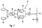
- the two sensors 25, 26 have a quotient formation level 28 or a divider connected. Of the The output of this quotient formation stage 28 is one each Input of two comparators 29, 30 for the two end positions connected. The corresponding end positions, where the switch-off is to take place, can be made via comparison inputs 31, 32 can be specified.
- the outputs of the Comparators 29, 30 control one via an OR gate 33 Switch 34 in the circuit of the drive motor 19th
- the one shown in FIG Circuit also implemented by a microcontroller or the corresponding functions will be additional through an already existing microcontroller realized.
- the basic idea of the present invention is now that in every webbing position and therefore in every position the shutter curtain a certain speed ratio between the deflection roller 17 and the take-up reel 10 is present.
- the speed of the deflection roller 17 is in fixed relation to the belt speed.
- This Speed ratio can thus the webbing position or the position of the roller shutter curtain or another the webbing driven blackout device, such as a blind or a slat curtain.
- the diameter of the webbing 35 equal to the diameter of the pulley 17 and further assume that the diameter of the take-up reel 10 three and a half times the diameter of the corresponds to second gear 22, is under the further requirement that the number of teeth of the second Gear wheel 22 of the number of elements 24 of the guide roller 17 corresponds to the speed ratio of the speed of the Deflection roller 17 for the speed of the second gear wheel 22 1: 3.5.
- the speed ratio is the lower one End position of the roller shutter curtain reached. If you now continues as an example assuming that in the upper End position of the roller shutter curtain the diameter of the webbing roll 35 3.5 times the diameter of the Deflection roller 17, then the speed ratio is 1: 1.
- this speed ratio formed by the signals f1 of the first Sensor 25 by the signals f2 of the second sensor 26 be divided.
- the comparators 29, 30 are used as comparison values the lower cut-off value Au and the upper one Switch-off value Ao specified that the present there Speed ratio.
- the one then generated Output signal of the comparators 29, 30 leads to opening the switch 34 and thus to switch off the drive motor 19.
- the switchover required when switching off the direction of rotation of the drive motor can be according to the state of the art to ensure that when the drive motor is switched on again a switching command or a radio signal the opposite Drive direction is present.
- the restart the drive motor can be by manual or wireless Closing the switch 34 take place.
- the comparison values Au and Ao can be stored, for example by the fact that each in the Quotient formation level 28 values temporarily stored become. In a learning mode you can then lower switch-off position the last saved value as Value Au and accordingly in the upper switch-off position the value Ao can be stored as a comparison value. This can be done manually or automatically.
- the second sensor 26 another gear or directly the sprocket of the take-up reel Scan 10 or vary the number of elements 24 to be scanned in or on the deflection roller 17.
Landscapes
- Engineering & Computer Science (AREA)
- Structural Engineering (AREA)
- Architecture (AREA)
- Civil Engineering (AREA)
- Operating, Guiding And Securing Of Roll- Type Closing Members (AREA)
- Blinds (AREA)
- Forklifts And Lifting Vehicles (AREA)
- Paper (AREA)
- Jib Cranes (AREA)
Abstract
Description
Die Erfindung betrifft eine Vorrichtung zur Steuerung der Bewegung einer Verdunkelungsvorrichtung, insbesondere eines Rolladens, eines Rollos oder eines Lamellenvorhangs, mittels eines Gurtbands nach der Gattung des Anspruchs 1.The invention relates to a device for controlling the Movement of a blackout device, in particular a roller shutter, a roller blind or a slat curtain, by means of a belt strap according to the preamble of claim 1.
Bei einer derartigen, aus der DE-A-195 23914 bekannten Vorrichtung werden die Umdrehungen einer Umlenkrolle für das Gurtband erfaßt. Ohne weitere End- oder Referenzschalter sind die erfaßten Signale nur für eine relative Messung brauchbar. Eine automatische Fehlerkorrektur ist nicht möglich, das heißt, selbst wenn Referenzwerte eingespeichert werden, so besteht die Gefahr, daß diese durch Fehlsignale, Störimpulse oder Alterungserscheinungen ihre genaue Zuordnung zu den Endpositionen verlieren.In such a known from DE-A-195 23914 Device is the turns of a pulley for the webbing is grasped. Without further limit or reference switches the detected signals are only for a relative Measurement usable. An automatic error correction is not possible, that is, even if reference values are stored become, there is a risk that this by False signals, interference pulses or signs of aging your lose exact assignment to the end positions.
Weiterhin ist aus der DE-A-44 04 682 eine Vorrichtung zur Bewegungssteuerung bekannt, bei der die Anzahl der Umdrehungen des Motors oder eines damit verbundenen Getriebeteils zur Messung des zurückgelegten Wegs des Rollladenpanzers benutzt wird. Auch hier liegen dieselben Nachteile vor, das heißt, es müssen entweder zusätzliche End- oder Referenzschalter eingesetzt werden, oder es ist eine häufige Nachjustierung von gegebenenfalls gespeicherten und zugeordneten Positionswerten erforderlich. Furthermore, from DE-A-44 04 682 a device for Motion control known in which the number of revolutions of the engine or a gear part connected to it for measuring the distance covered by the roller shutter curtain is used. Here too are the same Disadvantages, that is, either need additional Limit or reference switches are used, or it is a frequent readjustment of any saved and assigned position values required.
Die erfindungsgemäße Vorrichtung mit den Merkmalen des Hauptanspruchs hat den Vorteil, daß durch dynamische Erfassung von lediglich zwei Sensorsignalen ein absoluter Wert über die jeweilige Position beispielsweise eines Rolladenpanzers erhalten werden kann. Die absolute Positionsbestimmung ist dabei unabhängig von der tatsächlichen Antriebsgeschwindigkeit. Werden beispielsweise gespeicherte Endpositionen durch einen Stromausfall oder ein unbeabsichtigtes Reset-Signal gelöscht, so können sie automatisch wiederhergestellt werden. Die Auswertung der beiden Sensorsignale ist auf einfache Weise realisierbar.The inventive device with the features of The main claim has the advantage that through dynamic detection an absolute of only two sensor signals Value over the respective position, for example one Roller shutter curtain can be obtained. The absolute position determination is independent of the actual Drive speed. For example, be saved End positions due to a power failure or an unintentional Reset signal cleared, so you can automatically be restored. The evaluation of the Both sensor signals can be implemented in a simple manner.
Durch die in den Unteransprüchen aufgeführten Maßnahmen sind vorteilhafte Weiterbildungen und Verbesserungen der im Hauptanspruch angegebenen Vorrichtung möglich.By the measures listed in the subclaims are advantageous developments and improvements of device specified in the main claim possible.
Durch die Sensormittel sind zweckmäßigerweise Markierungen oder Zähne an der Rolle und der Aufwickelhaspel oder dem damit in Antriebsverbindung stehenden Rotationselement abtastbar und in entsprechende Signale umsetzbar. Dabei sind die Signale der Sensormittel vorzugsweise Zählsignale oder davon abgeleitete Frequenzsignale.Markings are expediently provided by the sensor means or teeth on the reel and take-up reel or that thus rotating element in drive connection scannable and convertible into corresponding signals. Here the signals from the sensor means are preferably counting signals or frequency signals derived therefrom.
Eine einfache Auswertemöglichkeit besteht darin, daß die Signale der Sensormittel einer Quotientenbildungsstufe zur Bildung der Verhältniswerte zuführbar sind.A simple evaluation option is that the Signals from the sensor means of a quotient formation stage Formation of the ratio values can be supplied.
In einer bevorzugten Ausführung weist die Abschalteinrichtung wenigstens einen Komparator zum Vergleich der aus den Verhältniswerten abgeleiteten Positionswerte mit wenigstens einem vorgebbaren Abschalt-Positionswert auf, wobei durch den wenigstens einen Komparator die Abschalteinrichtung betätigbar ist. In a preferred embodiment, the shutdown device at least one comparator to compare the the position values derived from the ratio values at least one predefinable switch-off position value, wherein the shutdown device by the at least one comparator can be actuated.
Die vom Gurtband angetriebene Rolle ist zweckmäßigerweise die ohnehin erforderliche Gurtumlenkrolle.The reel driven by the webbing is convenient the belt deflection roller that is required anyway.
Ein Ausführungsbeispiel der Erfindung ist in der Zeichnung dargestellt und in der nachfolgenden Beschreibung näher erläutert. Es zeigen:
- Fig. 1
- eine schematische Längsschnittdarstellung einer elektrischen Antriebsvorrichtung für einen Rolladenpanzer über einen Antriebsgurt und
- Fig. 2
- ein Blockschaltbild einer elektronischen Vorrichtung zur Bewegungssteuerung.
- Fig. 1
- is a schematic longitudinal sectional view of an electric drive device for a roller shutter curtain via a drive belt and
- Fig. 2
- a block diagram of an electronic device for motion control.
Gemäß Fig. 1 enthält ein flacher Gurtkasten 12 eine Aufwickelhaspel
10 für ein Gurtband 11, wobei der Gurtkasten
12 so gestaltet ist, daß er in eine ohnehin vorhandene
Wandausnehmung 13 für eine manuell bedienbare Aufwickelrolle
in einer Gebäudewand 14 eingeschoben werden kann. An
diesem Gurtkasten 12 ist ein Motorgehäuse 15 so angebracht,
daß dieses außerhalb der Wandausnehmung 13 flach
an der Gebäudewand 14 anliegt und dabei die Begrenzungen
der Wandausnehmung 13 nach allen vier Seiten hin übergreift,
so daß die Wandausnehmung 13 vollständig abgedeckt
ist. Dabei kann das Motorgehäuse 15 auch vom Gurtkasten 12
abnehmbar ausgebildet sein.1, a
Das Gurtband 11 kann mittels der Aufwickelhaspel 10 im
Gurtkasten 12, die dort im wesentlichen mittig drehbar
gelagert ist, auf- und abgewickelt werden und verläuft von
dieser aus über eine Umlenkrolle 17 durch das Motorgehäuse
15 und durch eine nicht dargestellte Gehäuseöffnung nach
außen und dann im wesentlichen parallel zur Gebäudewand 14
nach oben zu einem nicht dargestellten, in üblicher Weise
ausgebildeten Rolladenkasten, in dem eine drehbar gelagerte
Wickelwelle zum Auf- und Abwickeln des Rolladenpanzers
vom Gurtband 11 angetrieben wird.The
Im Motorgehäuse 15 ist im mittleren Bereich ein Untersetzungsgetriebe
18 angeordnet, das durch einen elektrischen
Antriebsmotor 19 angetrieben wird. Der Antriebsmotor
19 treibt über ein Schneckenrad 20 ein erstes Getrieberad
21, dieses ein zweites Getrieberad 22 und dieses die Aufwickelhaspel
10 an. Hierzu besitzt die Aufwickelhaspel 10
einen Zahnkranz 23. In der aus nicht-ferromagnetischem
Material, beispielsweise aus Kunststoff, bestehenden Umlenkrolle
17 sind ferromagnetische oder permanentmagnetische
Elemente 24 im Bereich des Außenumfangs eingelassen.
Bei der Bewegung des Gurtbands 11 dreht sich die Umlenkrolle
17, und die Elemente 24 passieren einen ersten
Sensor 25, in dem jedes dieser Elemente 24 ein Signal erzeugt.
Im Falle von permanentmagnetischen Elementen 24
kann der Sensor beispielsweise als Reed-Schalter ausgebildet
sein. Alternativ hierzu ist es möglich, den ersten
Sensor 25 gemäß der DE-A-44 14 280 auszubilden.In the middle of the
Ein zweiter Sensor 26, der ebenfalls gemäß der DE-A-44
14 280 ausgebildet sein kann, ist im Bereich der Zähne
des zweiten Getrieberads 22 angeordnet, so daß bei der
Drehung dieses Getrieberads 22 jeder Zahn ein Signal im
zweiten Sensor 26 erzeugt. Die beiden Sensoren 25, 26 sind
mit einer elektronischen Steuereinrichtung 27 verbunden,
die im unteren Bereich des Motorgehäuses 15 untergebracht
ist.A
Als Antrieb des beispielsweise als Gleichstrommotor ausgebildeten
Antriebsmotors 19 dienen nicht dargestellte
Batterien, beispielsweise im oberen Bereich des Motorgehäuses
15, die auch als wiederaufladbare Batterien ausgebildet
sein können. Alternativ oder zusätzlich ist auch eine
Stromversorgung über ein Anschlußkabel möglich. Die Bedienung
des Antriebsmotors 19 bzw. der elektronischen
Steuereinrichtung 27 erfolgt über nicht dargestellte Bedienungselemente
an der von der Gebäudewand 14 wegweisenden
flachen Außenseite des Motorgehäuses 15.As a drive for the, for example, a DC
In Fig. 2 ist derjenige Bereich der elektronischen Steuereinrichtung
27 im Blockschaltbild dargestellt, der die
Abschaltung des Antriebsmotors 19 bei Erreichen der beiden
Endpositionen betrifft. Prinzipiell könnten selbstverständlich
auf dieselbe Weise auch Abschaltungen an gewünschten
Zwischenpositionen vorgenommen werden. Im übrigen
ist eine derartige elektronische Steuereinrichtung
beispielsweise aus der DE-A-440 4682 bekannt.2 is that area of the
Die beiden Sensoren 25, 26 sind mit einer Quotientenbildungsstufe
28 bzw. einem Dividierer verbunden. Der
Ausgang dieser Quotientenbildungsstufe 28 ist mit je einem
Eingang zweier Komparatoren 29, 30 für die beiden Endpositionen
verbunden. Die entsprechenden Endpositionen,
bei denen die Abschaltung erfolgen soll, können über Vergleichseingänge
31, 32 vorgegeben werden. Die Ausgänge der
Komparatoren 29, 30 steuern über ein ODER-Glied 33 einen
Ausschalter 34 im Stromkreis des Antriebsmotors 19.
Selbstverständlich kann die in Fig. 2 dargestellte
Schaltung auch durch einen Mikrocontroller realisiert
werden, oder die entsprechenden Funktionen werden zusätzlich
durch einen ohnehin vorhandenen Mikrocontroller
realisiert.The two
Beim Aufwickeln des Gurtbands 11 auf die Aufwickelhaspel
10 nimmt der Durchmesser des Gurtbandwickels 35 immer mehr
zu. Da sich die Aufwickelhaspel 10 mit konstanter Drehzahl
dreht, nimmt die Gurtbandgeschwindigkeit immer mehr zu, so
daß sich entsprechend die Drehzahl der Umlenkrolle 17
stetig erhöht. Beim Abwickeln verlaufen diese Vorgänge in
umgekehrter Weise.When winding the
Die Grundidee der vorliegenden Erfindung besteht nun darin,
daß in jeder Gurtbandposition und damit in jeder Position
des Rolladenpanzers ein bestimmtes Drehzahlverhältnis
zwischen der Umlenkrolle 17 und der Aufwickelhaspel 10
vorliegt. Die Drehzahl der Umlenkrolle 17 steht dabei in
festem Verhältnis zur Gurtbandgeschwindigkeit. Über dieses
Drehzahlverhältnis kann somit die Gurtbandposition bzw.
die Position des Rolladenpanzers oder einer anderen durch
das Gurtband angetriebenen Verdunkelungsvorrichtung, wie
eines Rollos oder eines Lamellenvorhangs, bestimmt werden.
Ist beispielsweise in der unteren Endposition eines abgewickelten
Rolladenpanzers der Durchmesser des Gurtbandwickels
35 gleich dem Durchmesser der Umlenkrolle 17 und
sei weiterhin angenommen, daß der Durchmesser der Aufwickelhaspel
10 dem Dreieinhalbfachen des Durchmessers des
zweiten Getrieberads 22 entspricht, so ist unter der
weiteren Voraussetzung, daß die Zähnezahl des zweiten
Getrieberads 22 der Zahl der Elemente 24 der Umlenkrolle
17 entspricht, das Drehzahlverhältnis der Drehzahl der
Umlenkrolle 17 zur Drehzahl des zweiten Getrieberads 22
1 : 3,5. Bei diesem Drehzahlverhältnis ist also die untere
Endposition des Rolladenpanzers erreicht. Wenn man nun
weiterhin als Beispiel davon ausgeht, daß in der oberen
Endposition des Rolladenpanzers der Durchmesser des Gurtbandwickels
35 3,5 mal so groß wie der Durchmesser der
Umlenkrolle 17 ist, so beträgt dann das Drehzahlverhältnis
1 : 1. In der Quotientenbildungsstufe 28 wird dieses Drehzahlverhältnis
gebildet, indem die Signale f1 des ersten
Sensors 25 durch die Signale f2 des zweiten Sensors 26
dividiert werden. Den Komparatoren 29, 30 werden als Vergleichswerte
der untere Abschaltwert Au und der obere
Abschaltwert Ao vorgegeben, die dem dort vorliegenden
Drehzahlverhältnis entsprechen. Das jeweils dann erzeugte
Ausgangssignal der Komparatoren 29, 30 führt zum Öffnen
des Ausschalters 34 und damit zum Abschalten des Antriebsmotors
19. Die beim Abschalten erforderliche Umschaltung
der Drehrichtung des Antriebsmotors kann gemäß dem
angegebenen Stand der Technik erfolgen, um sicherzustellen,
daß beim Wiedereinschalten des Antriebsmotors durch
einen Schaltbefehl oder ein Funksignal die entgegengesetzte
Antriebsrichtung vorliegt. Das Wiedereinschalten
des Antriebsmotors kann durch manuelles oder drahtloses
Schließen des Ausschalters 34 erfolgen.The basic idea of the present invention is now
that in every webbing position and therefore in every position
the shutter curtain a certain speed ratio
between the deflection roller 17 and the take-
Das Einspeichern der Vergleichswerte Au und Ao kann beispielsweise
dadurch erfolgen, daß die jeweils in der
Quotientenbildungsstufe 28 gebildeten Werte zwischengespeichert
werden. In einem Lernmodus können dann in der
unteren Abschaltposition der zuletzt gespeicherte Wert als
Wert Au und entsprechend in der oberen Abschaltposition
der Wert Ao als Vergleichswert eingespeichert werden. Dies
kann manuell oder automatisch erfolgen.The comparison values Au and Ao can be stored, for example
by the fact that each in the
Soll das Signalverhältnis zwischen den Signalfolgen f1 und
f2 verändert werden, so kann entweder der zweite Sensor 26
ein anderes Getrieberad oder direkt den Zahnkranz der Aufwickelhaspel
10 abtasten, oder man variiert die Zahl der
abzutastenden Elemente 24 in oder an der Umlenkrolle 17.If the signal ratio between the signal sequences f1 and
f2 can be changed, either the
Claims (8)
Applications Claiming Priority (2)
| Application Number | Priority Date | Filing Date | Title |
|---|---|---|---|
| DE19805158A DE19805158C2 (en) | 1998-02-10 | 1998-02-10 | Device for controlling the movement of a blackout device |
| DE19805158 | 1998-02-10 |
Publications (3)
| Publication Number | Publication Date |
|---|---|
| EP0936341A2 true EP0936341A2 (en) | 1999-08-18 |
| EP0936341A3 EP0936341A3 (en) | 2002-02-13 |
| EP0936341B1 EP0936341B1 (en) | 2003-08-13 |
Family
ID=7857120
Family Applications (1)
| Application Number | Title | Priority Date | Filing Date |
|---|---|---|---|
| EP99101259A Expired - Lifetime EP0936341B1 (en) | 1998-02-10 | 1999-01-23 | Arrangement for controlling the movement of a darkening device |
Country Status (4)
| Country | Link |
|---|---|
| EP (1) | EP0936341B1 (en) |
| AT (1) | ATE247218T1 (en) |
| DE (2) | DE19805158C2 (en) |
| ES (1) | ES2205609T3 (en) |
Cited By (2)
| Publication number | Priority date | Publication date | Assignee | Title |
|---|---|---|---|---|
| WO2001057352A1 (en) * | 2000-02-05 | 2001-08-09 | Amnon Ribak | Reduced-energy requiring rolling-mechanism |
| EP1929181A1 (en) * | 2005-08-26 | 2008-06-11 | PH. B INNOVATIONS Sarl | Twisted belt transmission |
Families Citing this family (5)
| Publication number | Priority date | Publication date | Assignee | Title |
|---|---|---|---|---|
| DE19941483C2 (en) * | 1999-08-06 | 2001-09-27 | Somfy Feinmech & Elektrotech | Drive device for a blackout device driven by a webbing |
| DE19946366A1 (en) * | 1999-09-28 | 2001-03-29 | Roland Voehringer | Room roller-blind monitoring device, uses rotary roller positioned on roller blind for detecting movement of the blind |
| DE29921653U1 (en) * | 1999-10-06 | 2001-02-15 | Rademacher, Wilhelm, 46414 Rhede | Belt winder for a roller shutter belt or the like. |
| DE20316494U1 (en) * | 2003-10-24 | 2004-01-22 | Rademacher, Wilhelm | Belt winder for a blackout device such as a roller shutter |
| CN101240690B (en) * | 2007-02-09 | 2011-05-04 | 浙江康泰电气有限公司 | Coiling type light-shading curtain driving device |
Citations (3)
| Publication number | Priority date | Publication date | Assignee | Title |
|---|---|---|---|---|
| DE4404682A1 (en) | 1994-02-15 | 1995-08-17 | Bosch Gmbh Robert | Device for electronically controlling the movements of a blackout device |
| DE4414280A1 (en) | 1994-04-23 | 1995-10-26 | Bosch Gmbh Robert | Device for detecting the rotational movement of a toothed or cam wheel |
| DE19523914C1 (en) | 1995-06-30 | 1996-09-05 | Bosch Gmbh Robert | Shutter shield drive belt movement detection device |
Family Cites Families (4)
| Publication number | Priority date | Publication date | Assignee | Title |
|---|---|---|---|---|
| DE2650665C3 (en) * | 1976-11-05 | 1979-07-05 | Grundig E.M.V. Elektro-Mechanische Versuchsanstalt Max Grundig, 8510 Fuerth | Method and device for determining the elapsed playing time or tape length and / or the remaining time of cassettes or reels of tape-shaped information carriers |
| DE4407919A1 (en) * | 1994-03-09 | 1995-09-14 | Tornado Antriebstech Gmbh | Control system for conveyor or roller or hinged door |
| DE19519020A1 (en) * | 1995-05-24 | 1996-11-28 | Bosch Gmbh Robert | Device for the electronic control of the movements of a roller shutter |
| DE29722936U1 (en) * | 1997-12-18 | 1998-03-05 | Rademacher, Wilhelm, 46414 Rhede | Belt winder for a blackout device |
-
1998
- 1998-02-10 DE DE19805158A patent/DE19805158C2/en not_active Expired - Fee Related
-
1999
- 1999-01-23 ES ES99101259T patent/ES2205609T3/en not_active Expired - Lifetime
- 1999-01-23 EP EP99101259A patent/EP0936341B1/en not_active Expired - Lifetime
- 1999-01-23 DE DE59906549T patent/DE59906549D1/en not_active Expired - Lifetime
- 1999-01-23 AT AT99101259T patent/ATE247218T1/en not_active IP Right Cessation
Patent Citations (3)
| Publication number | Priority date | Publication date | Assignee | Title |
|---|---|---|---|---|
| DE4404682A1 (en) | 1994-02-15 | 1995-08-17 | Bosch Gmbh Robert | Device for electronically controlling the movements of a blackout device |
| DE4414280A1 (en) | 1994-04-23 | 1995-10-26 | Bosch Gmbh Robert | Device for detecting the rotational movement of a toothed or cam wheel |
| DE19523914C1 (en) | 1995-06-30 | 1996-09-05 | Bosch Gmbh Robert | Shutter shield drive belt movement detection device |
Cited By (2)
| Publication number | Priority date | Publication date | Assignee | Title |
|---|---|---|---|---|
| WO2001057352A1 (en) * | 2000-02-05 | 2001-08-09 | Amnon Ribak | Reduced-energy requiring rolling-mechanism |
| EP1929181A1 (en) * | 2005-08-26 | 2008-06-11 | PH. B INNOVATIONS Sarl | Twisted belt transmission |
Also Published As
| Publication number | Publication date |
|---|---|
| DE19805158C2 (en) | 2003-06-26 |
| EP0936341A3 (en) | 2002-02-13 |
| ES2205609T3 (en) | 2004-05-01 |
| DE59906549D1 (en) | 2003-09-18 |
| EP0936341B1 (en) | 2003-08-13 |
| DE19805158A1 (en) | 1999-08-12 |
| ATE247218T1 (en) | 2003-08-15 |
Similar Documents
| Publication | Publication Date | Title |
|---|---|---|
| EP0770757B2 (en) | Method of actuating awnings or the like by an electric motor | |
| EP0552459B1 (en) | Safety device for roller shutters and similar closures | |
| DE3829405C2 (en) | ||
| EP0100852A1 (en) | Circuit arrangement for rising and lowering a motor-operated antenna | |
| DE3806733A1 (en) | Arrangement for monitoring and controlling roller blinds and the like | |
| DE4138194C2 (en) | Method and device for detecting the position and direction of movement of units which are moved in a translatory and / or rotary manner | |
| DE10014073B4 (en) | Security device for motorized windows | |
| EP2063336B2 (en) | Drive assembly for a screening device | |
| DE4407342C2 (en) | Blackout device with an awning, an external blind or the like | |
| EP0936341B1 (en) | Arrangement for controlling the movement of a darkening device | |
| EP0544135B1 (en) | Method and device for the control of the end positions of electric motor driven actuators | |
| EP0751279B1 (en) | Device for controlling the movement of a driving belt for a roller shutter | |
| DE19522622C2 (en) | Device for controlling a motor drive | |
| EP0678646A1 (en) | Device for acquisition of rotary movement from a gear or cam wheel | |
| DE19941483C2 (en) | Drive device for a blackout device driven by a webbing | |
| DE4438851C2 (en) | Device for controlling a motor drive | |
| DE19741620C2 (en) | Method for setting the end positions of an actuator driven by an electric motor | |
| DE4229045A1 (en) | Commutator motor speed, direction and angle sensor for vehicle sliding roof or electric window - extends segment of commutator to L=shaped track which runs along circumference of commutator, and has sliding contact for sensing voltage of extended track | |
| DE102014105089B4 (en) | Drive device for a surface element | |
| EP1758224A1 (en) | Device for associating a command signal to a direction of rotation of an electric motor for a movable barrier | |
| DE19942512A1 (en) | Electric drive device for blackout or shading devices | |
| EP1956346B1 (en) | Device for controlling the standstill state of a motorised drive mechanism | |
| EP1526248B1 (en) | Tape drum for a darkening device, like a roller shutter | |
| DE29510657U1 (en) | Device for detecting the movement of a drive belt for a roller shutter curtain | |
| DE10214434A1 (en) | End shut-down device for automatically adjusting drives of roller shutters or awnings, having a position signal which is an electrical quantity with its value corresponding the position of drive object |
Legal Events
| Date | Code | Title | Description |
|---|---|---|---|
| PUAI | Public reference made under article 153(3) epc to a published international application that has entered the european phase |
Free format text: ORIGINAL CODE: 0009012 |
|
| AK | Designated contracting states |
Kind code of ref document: A2 Designated state(s): AT BE CH CY DE DK ES FI FR GB GR IE IT LI LU MC NL PT SE Kind code of ref document: A2 Designated state(s): AT BE CH DE DK ES FR GB IT LI NL SE |
|
| AX | Request for extension of the european patent |
Free format text: AL;LT;LV;MK;RO;SI |
|
| RAP1 | Party data changed (applicant data changed or rights of an application transferred) |
Owner name: SOMFY FEINMECHANIK UND ELEKTROTECHNIK GMBH |
|
| PUAL | Search report despatched |
Free format text: ORIGINAL CODE: 0009013 |
|
| AK | Designated contracting states |
Kind code of ref document: A3 Designated state(s): AT BE CH CY DE DK ES FI FR GB GR IE IT LI LU MC NL PT SE |
|
| AX | Request for extension of the european patent |
Free format text: AL;LT;LV;MK;RO;SI |
|
| 17P | Request for examination filed |
Effective date: 20020404 |
|
| 17Q | First examination report despatched |
Effective date: 20020829 |
|
| AKX | Designation fees paid |
Free format text: AT BE CH DE DK ES FR GB IT LI NL SE |
|
| GRAH | Despatch of communication of intention to grant a patent |
Free format text: ORIGINAL CODE: EPIDOS IGRA |
|
| GRAH | Despatch of communication of intention to grant a patent |
Free format text: ORIGINAL CODE: EPIDOS IGRA |
|
| GRAA | (expected) grant |
Free format text: ORIGINAL CODE: 0009210 |
|
| AK | Designated contracting states |
Designated state(s): AT BE CH DE DK ES FR GB IT LI NL SE |
|
| PG25 | Lapsed in a contracting state [announced via postgrant information from national office to epo] |
Ref country code: NL Free format text: LAPSE BECAUSE OF FAILURE TO SUBMIT A TRANSLATION OF THE DESCRIPTION OR TO PAY THE FEE WITHIN THE PRESCRIBED TIME-LIMIT Effective date: 20030813 Ref country code: GB Free format text: LAPSE BECAUSE OF FAILURE TO SUBMIT A TRANSLATION OF THE DESCRIPTION OR TO PAY THE FEE WITHIN THE PRESCRIBED TIME-LIMIT Effective date: 20030813 |
|
| REG | Reference to a national code |
Ref country code: GB Ref legal event code: FG4D Free format text: NOT ENGLISH |
|
| REG | Reference to a national code |
Ref country code: CH Ref legal event code: EP |
|
| REG | Reference to a national code |
Ref country code: IE Ref legal event code: FG4D Free format text: GERMAN |
|
| REF | Corresponds to: |
Ref document number: 59906549 Country of ref document: DE Date of ref document: 20030918 Kind code of ref document: P |
|
| PG25 | Lapsed in a contracting state [announced via postgrant information from national office to epo] |
Ref country code: SE Free format text: LAPSE BECAUSE OF FAILURE TO SUBMIT A TRANSLATION OF THE DESCRIPTION OR TO PAY THE FEE WITHIN THE PRESCRIBED TIME-LIMIT Effective date: 20031113 Ref country code: DK Free format text: LAPSE BECAUSE OF FAILURE TO SUBMIT A TRANSLATION OF THE DESCRIPTION OR TO PAY THE FEE WITHIN THE PRESCRIBED TIME-LIMIT Effective date: 20031113 |
|
| PG25 | Lapsed in a contracting state [announced via postgrant information from national office to epo] |
Ref country code: LI Free format text: LAPSE BECAUSE OF NON-PAYMENT OF DUE FEES Effective date: 20040131 Ref country code: CH Free format text: LAPSE BECAUSE OF NON-PAYMENT OF DUE FEES Effective date: 20040131 |
|
| NLV1 | Nl: lapsed or annulled due to failure to fulfill the requirements of art. 29p and 29m of the patents act | ||
| GBV | Gb: ep patent (uk) treated as always having been void in accordance with gb section 77(7)/1977 [no translation filed] |
Effective date: 20030813 |
|
| REG | Reference to a national code |
Ref country code: IE Ref legal event code: FD4D |
|
| REG | Reference to a national code |
Ref country code: ES Ref legal event code: FG2A Ref document number: 2205609 Country of ref document: ES Kind code of ref document: T3 |
|
| ET | Fr: translation filed | ||
| PLBE | No opposition filed within time limit |
Free format text: ORIGINAL CODE: 0009261 |
|
| STAA | Information on the status of an ep patent application or granted ep patent |
Free format text: STATUS: NO OPPOSITION FILED WITHIN TIME LIMIT |
|
| 26N | No opposition filed |
Effective date: 20040514 |
|
| REG | Reference to a national code |
Ref country code: CH Ref legal event code: PL |
|
| PGFP | Annual fee paid to national office [announced via postgrant information from national office to epo] |
Ref country code: AT Payment date: 20050125 Year of fee payment: 7 |
|
| PG25 | Lapsed in a contracting state [announced via postgrant information from national office to epo] |
Ref country code: AT Free format text: LAPSE BECAUSE OF NON-PAYMENT OF DUE FEES Effective date: 20060123 |
|
| PGFP | Annual fee paid to national office [announced via postgrant information from national office to epo] |
Ref country code: IT Payment date: 20080126 Year of fee payment: 10 |
|
| PGFP | Annual fee paid to national office [announced via postgrant information from national office to epo] |
Ref country code: FR Payment date: 20080118 Year of fee payment: 10 |
|
| PGFP | Annual fee paid to national office [announced via postgrant information from national office to epo] |
Ref country code: BE Payment date: 20080123 Year of fee payment: 10 |
|
| REG | Reference to a national code |
Ref country code: FR Ref legal event code: ST Effective date: 20091030 |
|
| PG25 | Lapsed in a contracting state [announced via postgrant information from national office to epo] |
Ref country code: BE Free format text: LAPSE BECAUSE OF NON-PAYMENT OF DUE FEES Effective date: 20090131 |
|
| PG25 | Lapsed in a contracting state [announced via postgrant information from national office to epo] |
Ref country code: FR Free format text: LAPSE BECAUSE OF NON-PAYMENT OF DUE FEES Effective date: 20090202 |
|
| PG25 | Lapsed in a contracting state [announced via postgrant information from national office to epo] |
Ref country code: IT Free format text: LAPSE BECAUSE OF NON-PAYMENT OF DUE FEES Effective date: 20090123 |
|
| PGFP | Annual fee paid to national office [announced via postgrant information from national office to epo] |
Ref country code: DE Payment date: 20110115 Year of fee payment: 13 |
|
| PGFP | Annual fee paid to national office [announced via postgrant information from national office to epo] |
Ref country code: ES Payment date: 20110121 Year of fee payment: 13 |
|
| PG25 | Lapsed in a contracting state [announced via postgrant information from national office to epo] |
Ref country code: DE Free format text: LAPSE BECAUSE OF NON-PAYMENT OF DUE FEES Effective date: 20120801 |
|
| REG | Reference to a national code |
Ref country code: DE Ref legal event code: R119 Ref document number: 59906549 Country of ref document: DE Effective date: 20120801 |
|
| REG | Reference to a national code |
Ref country code: ES Ref legal event code: FD2A Effective date: 20130708 |
|
| PG25 | Lapsed in a contracting state [announced via postgrant information from national office to epo] |
Ref country code: ES Free format text: LAPSE BECAUSE OF NON-PAYMENT OF DUE FEES Effective date: 20120124 |