EP0936378A1 - Kette für einen Schubkettenantrieb und deren Verwendung - Google Patents
Kette für einen Schubkettenantrieb und deren Verwendung Download PDFInfo
- Publication number
- EP0936378A1 EP0936378A1 EP99102474A EP99102474A EP0936378A1 EP 0936378 A1 EP0936378 A1 EP 0936378A1 EP 99102474 A EP99102474 A EP 99102474A EP 99102474 A EP99102474 A EP 99102474A EP 0936378 A1 EP0936378 A1 EP 0936378A1
- Authority
- EP
- European Patent Office
- Prior art keywords
- chain
- plates
- bolts
- chain according
- longitudinal axis
- Prior art date
- Legal status (The legal status is an assumption and is not a legal conclusion. Google has not performed a legal analysis and makes no representation as to the accuracy of the status listed.)
- Granted
Links
- 206010052904 Musculoskeletal stiffness Diseases 0.000 description 6
- 238000013459 approach Methods 0.000 description 4
- 238000005452 bending Methods 0.000 description 4
- 238000005096 rolling process Methods 0.000 description 3
- 238000003698 laser cutting Methods 0.000 description 2
- 238000004519 manufacturing process Methods 0.000 description 2
- 239000000463 material Substances 0.000 description 2
- 238000012546 transfer Methods 0.000 description 2
- 241000782128 Albizia adianthifolia Species 0.000 description 1
- 230000006978 adaptation Effects 0.000 description 1
- 230000005540 biological transmission Effects 0.000 description 1
- 230000015572 biosynthetic process Effects 0.000 description 1
- 238000011161 development Methods 0.000 description 1
- 230000018109 developmental process Effects 0.000 description 1
- 230000002349 favourable effect Effects 0.000 description 1
- 238000009434 installation Methods 0.000 description 1
- 230000007774 longterm Effects 0.000 description 1
- 238000003754 machining Methods 0.000 description 1
- 239000002184 metal Substances 0.000 description 1
- 238000000034 method Methods 0.000 description 1
- 238000004080 punching Methods 0.000 description 1
- 239000011265 semifinished product Substances 0.000 description 1
- 238000004513 sizing Methods 0.000 description 1
- 239000011343 solid material Substances 0.000 description 1
- 125000006850 spacer group Chemical group 0.000 description 1
Images


Classifications
-
- F—MECHANICAL ENGINEERING; LIGHTING; HEATING; WEAPONS; BLASTING
- F16—ENGINEERING ELEMENTS AND UNITS; GENERAL MEASURES FOR PRODUCING AND MAINTAINING EFFECTIVE FUNCTIONING OF MACHINES OR INSTALLATIONS; THERMAL INSULATION IN GENERAL
- F16G—BELTS, CABLES, OR ROPES, PREDOMINANTLY USED FOR DRIVING PURPOSES; CHAINS; FITTINGS PREDOMINANTLY USED THEREFOR
- F16G13/00—Chains
- F16G13/18—Chains having special overall characteristics
- F16G13/20—Chains having special overall characteristics stiff; Push-pull chains
Definitions
- the invention relates to a chain according to the preamble of claim 1 and their use.
- Such chains are used for a wide variety of drive types and also used in chain gears.
- roller chains are known for this, the in connection with appropriately trained sprockets, which in turn is used for the input and output can be used.
- the outer straps are made of a round solid material producible into which the already mentioned groove is incorporated can be.
- the end faces of the outer plates are rounded on one side and the remaining part of the outer link end faces can be in stretched position in direct contact with the opposite end face of an adjacent one The outer plate is in direct contact.
- Such a known chain is material and costly to produce, since the groove is in a rod-shaped Semi-finished product through machining must be trained. This manufacturing process but does not ensure the high requirements for one high fit, so that both between the Inner and outer plates, as well as between neighboring ones Outer tabs or the bolt connections games occur and are also required in part, the lead to the fact that especially in the transfer of Shear forces with such a chain are not sufficient Stiffness can be achieved and this in can snap off in such cases.
- the chain according to the invention in push chain drives can be used is essentially three different parts assembled and engages thereby also returning to known elements.
- the individual chain links are connected with bolts and the rotary drive movement of one accordingly trained sprocket can over the bolt transferred to the chain so that the torque on the chain wheel for the drive is also transmitted as a force to the chain can.
- Such a chain link can be bent as a U-shape Be formed bracket and the other Chain link can be used as a flat inner link.
- the U-shaped bow, the outer and inner tabs have end faces on both sides on, the stretched chain of each juxtaposed brackets or outer and Inner tabs are in contact with each other, with the frontal support surfaces in the apex area of the U-shaped bracket can be used.
- the pressure forces occurring during the drive can be supported on these support surfaces and the chain is shaped by appropriate dimensioning of the U. Bracket or the outer and inner tabs in stretched Position stiff back, in particular the formation of the end support surface to bear is coming.
- interior and / or Outer plates used that are parallel to the longitudinal axis the bolts are angled.
- hers is Length dimensioned so that a game that between the bolts and the holes in the inner and External tabs are present or in the event that on the pin to reduce friction and wear Sleeves are pushed back with play, that Play between these sleeves and the bolts, in a straight line Position of the chain is compensated. That is, that in the extended position of the chain the front Support surfaces, except for a rounded one Edge area, on the side that is normally too driving sprockets shows, almost all over rest on adjacent outer and / or inner plates, so that a back stiffness, i.e. that in the direction of thrust a stiff chain is available that does not kink even with larger thrust forces.
- a chain with an inner and outer link, used with appropriately angled parts, which are lined up alternately are through the angled parts of the interior and Outer plates in connection with the corresponding Dimensioning the high required back stiffness can be achieved.
- This kinking can also be used for some applications be inexpensive, e.g. for one appropriate drive for opening and closing a Window can act.
- the chain drive can and the direct guidance of the chain on the drive be rigid and the chain is equal their flexibility determined certain required movement tolerances when opening and closing.
- the chain can also consist of two parts inside and / or Outer plates are assembled, the both parts of such an inner or outer tab in with respect to the longitudinal axis of the chain symmetrical and are parallel to the longitudinal axis of the bolts bent parts are directed towards each other so that in the assembled state of a chain, a U-shaped curved bracket formed from these two parts becomes.
- Such an embodiment not only has the required Back stiffness, but also a higher Level of lateral stability as the paired opposite end support surfaces, the two parts of such a tab, again on the neighboring end support surfaces of another Lugs are applied and thus a compensation of lateral forces can be achieved.
- brackets or the inner and outer plates are rounded in the lower edge area are to move around during the Rotation of the chain drive wheel and if necessary secure for rolling up such a chain.
- the radius or the shape curve form the rounded edge areas so that adjacent edge areas are more adjacent U-shaped bracket in the angled position of the chain are in direct contact with each other, so that a further support, in particular a side Kinking prevented, is achieved.
- a further support in particular a side Kinking prevented
- This support also equates to manufacturing tolerances of the individual chain elements, this is particularly exploited when the chains into the extended position from the rolled up or bent position (rolling movement) by the drive movement goes into the lifting movement.
- the inner tabs can only be designed so that with their help two neighboring brackets are connected and none of them or added only small supporting force components become. With the nose-shaped webs one can Lateral guidance can be achieved, the lateral Counteracts kinking.
- Chain the bolts can be attached and dimensioned in this way be at least one side of the chain width protrude and the protruding part of the bolts can intervene in a tour.
- the chain according to the invention can be advantageous also be designed so that the bolts with the chain links so connected that they alternate protrude on both sides of the chain and in each a partially circular arranged on both sides of the sprocket Intervene in the guide during the rotary movement can.
- the chain according to the invention can also be further developed be by the bracket or the outer and Inner tabs, for example by laser cutting or Stamping and bending are made so that in the lateral bending areas of the brackets on their faces recesses facing each other in pairs trained or on the curved part of outer plates are / is a recess in the nose-shaped webs of the inner brackets when assembled can.
- the cutouts and the nose-shaped webs should be dimensioned so that the both side surfaces of the webs with the end faces of the cutouts that are parallel to the support surfaces are aligned, in the extended position of the chain be in direct contact with each other, so that too Supporting forces are transmitted through these surfaces by positive locking can be.
- the inner straps can be further improved, if approaches are developed on them, which in the leak out narrower nose-shaped web subsequently. These approaches are parallel to the longitudinal direction of the stretched chain aligned and lie in stretched Position of the chain on the inner vertex surface the bracket on, so that lateral forces are absorbed can be avoided and kinking further avoided can be.
- the brackets can be next to flat crown areas can be manufactured more easily, even sublime be curved and thus a cheaper Adaptation to the diameter of the drive movement required while turning the sprocket is possible.
- a curved apex can also be used for your own or additional guidance are used, for this purpose preferably a low, e.g. very narrow guide surface used to reduce friction losses shall be.
- rotating elements those in almost point contact with the curved ones
- the top surfaces of the stirrups are in place and are used.
- Such elements can e.g. small in alignment be successively arranged cogs.
- Such an arrangement according to the invention can be very particularly advantageous Chain used in a linear actuator with the hatches, doors or windows of buildings should be opened and closed.
- a Thrust actuator used in addition to the invention Chain the chain wheel already mentioned also one electromotive or other suitable drive, if necessary a gear (e.g. a planetary gear) and such a drive is particularly cheap trained that the chain not extended directly be accommodated inside the linear actuator housing can.
- a gear e.g. a planetary gear
- the chain according to the invention can also work together with axially acting drive elements, such as e.g. Hydraulic cylinders, gearboxes or gas pressure springs be used.
- axially acting drive elements such as e.g. Hydraulic cylinders, gearboxes or gas pressure springs be used.
- a chain according to the invention with a Gas spring and possibly other drive elements for an emergency actuation of e.g. Vents in dangerous situations be used.
- the gas spring can be arranged cheaply and the available standing space for installation is more usable because the gas spring also orthogonal to the actual one Opening direction in which the chain acts arranged can be.
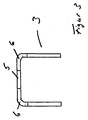
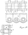
- Figures 1 to 3 show an example of a bracket, by punching and bending from a flat surface Metal plate can be made and one of the two different chain links for an inventive Represents chain.
- such a bracket 3 is made of one Manufactured piece and it has holes 11 for the Carrying out the bolt 1 on.
- the lateral support surfaces 12 on the legs of the bracket 3 for recording of the pressure forces when transmitting the thrust movement to Available.
- the bracket 3 to be used according to the invention is further improved by on both sides and on both Cutouts 6 are formed on the end faces.
- the cutouts 6 each include a support surface 5 and are dimensioned so that a nose-shaped bridge 7, which on the inner plates 2 of the second form of Chain links is formed in the opposite Recesses 6 of two adjacent brackets 2 can engage and the end faces of the recesses 6 and the side surfaces of the nose-shaped webs 7 in extended position of the chain in direct contact stand with each other and consequently also these surfaces can be used to absorb supporting forces.
- the bracket 3 are on the bolt 1 and in pairs connected by inner plates 2 and so one Chain formed by stringing together any length.
- FIG. 5 shows the front view of an example shown a chain according to the invention, the back stiff, however somewhat flexible in the lateral direction can be.
- This example of an inventive Chain uses an inner link 2 and an outer plate 3, each parallel to the Longitudinal axis of a pin 1, bent part.
- an additional tab is used in this example 15 used at the opposite of the outer plate 3 lying side of the inner plate 2 arranged and is held with the bolt 1.
- FIG. 6 there are two views in FIG. 6 an outer tab 3 with recesses 6 'in the upper bent part into which the nose-shaped web 7 ' an inner link 2, in the extended position of the chain can intervene positively, shown.
- the cutouts 6 'on the end support surfaces of the Outer plates 3 are dimensioned so that the nose-shaped web 7 'one between two outer plates 3 arranged inner tab completely in two recesses 6 'engage adjacent outer plates 3 and on the end faces of the outer plates 3 in Area of the recesses 6 'with its end faces can support.
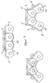
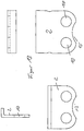
- Figure 7 are two representations of a part a chain that consists of two inner and one outer link is formed in two different positions shown.
- Both for the inner plates 2 and the outer plate 3 are here indented areas 13 and 13 ' present on these tabs, on the sides, the point to a sprocket not shown here, are trained.
- the arched areas 13 and 13 ' allow narrower bending radii of one such chain. This allows a smaller dimension Chain magazine can be used in the chain picked up and from which the chain by means of a drive, to exert a pushing force, extended can be.
- sleeves 16 are used in this example, which when mounting on the bolts 1, for connection of the different tabs, are pushed on, a certain between bolt 1 and sleeves Game must be adhered to in order to achieve this Movement when kinking such a chain, readily possible.
- this game by sizing and here in particular the length of the inner plates 2 and the outer plates 3 compensated accordingly, so that the thrust in the extended position, exclusively over the front support surfaces of at least the outer plates 3 and possibly also the inner plates 2 are transmitted.
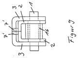
- FIG. 9 is a front view of an example shown a chain according to the invention, in which both the inner straps 2 and the outer straps 3 consist of two separate parts, whereby both bow-shaped elements when assembled form. Because the respective parts of the inner tabs 2 and the outer plates 3 are formed symmetrically are in the upper part of the chain End faces, in the longitudinal axis of the chain, together. The respective parts of the inner plates 2 and The shape of the outer plates 3 corresponds to that of as used in the example of Figure 5 have been.
- a sleeve is used again 16 arranged between the parts of the inner plate 2 and is pushed onto the bolt 1.
- the sleeve 16 also has the function of a spacer for the parts of the inner plate 2 and consequently also for the parts of the outer plate 3.
- part of the outer plate 3 is in four different views.
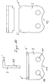
- FIG. 12 shows another example of an inventive one Chain shown in three views.
- Figures 13 and 14 each show three different ones Views, the parts used here for the inner plate 2 and the outer plate 3, which in turn with protruding bolts 1, in alternating sequence are interconnected, also on the Bolt 1 sleeves 16 can be pushed on.
- the outer plates 3 consist of flat Elements, as is also clear from Figure 14. Only the bores 11 are in the outer plates 3 for the implementation of the bolt 1 and the arcuate indented area 13 formed so that they are special be manufactured easily and inexpensively can.
- Inner tab 2 available, the upper part in turn angled orthogonally to the longitudinal axis of the bolt 1 is.
Landscapes
- Engineering & Computer Science (AREA)
- General Engineering & Computer Science (AREA)
- Mechanical Engineering (AREA)
- Devices For Conveying Motion By Means Of Endless Flexible Members (AREA)
- Portable Nailing Machines And Staplers (AREA)
- Auxiliary Devices For And Details Of Packaging Control (AREA)
- Chain Conveyers (AREA)
Abstract
Description
- Figuren 1 bis 3
- einen U-förmig gebogenen Bügel in drei Ansichten, wie er als Kettenglied einer erfindungsgemäßen Kette verwendet werden kann;
- Figur 4
- eine Ansicht eines Beispieles einer Innenlasche als Kettenglied;
- Figur 5
- ein Beispiel einer erfindungsgemäßen Kette, mit seitlicher Flexibilität in einer Vorderansicht;
- Figur 6
- zwei weitere Ansichten einer Kette gemäß Figur 5, mit Einzeldarstellungen der verwendeten Einzelteile;
- Figur 7
- einen aus drei einzelnen Laschen gebildeten Teil, einer Kette nach Figuren 5 und 6, in zwei verschiedenen Stellungen;
- Figur 8
- ein weiteres Beispiel einer erfindungsgemäßen Kette, mit drei dargestellten Einzellaschen, in einer Seitenansicht;
- Figur 9
- eine Vorderansicht einer Kette nach Figur 8;
- Figur 10
- vier Ansichten einer Außenlasche für eine Kette nach Figuren 8 und 9;
- Figur 11
- vier Ansichten einer Innenlasche einer Kette nach Figuren 8 und 9;
- Figur 12
- drei Ansichten eines weiteren Beispiels einer erfindungsgemäßen Kette;
- Figur 13
- vier Ansichten einer Innenlasche für eine Kette nach Figur 12 und
- Figur 14
- drei Ansichten einer Außenlasche für eine Kette nach Figur 12.
Claims (12)
- Kette für einen Schubkettenantrieb, mit durch Bolzen verbundenen Kettengliedern, die aus alternierend angeordneten Außen- und Innenlaschen gebildet ist, wobei zumindest die Außen- oder Innenlaschen stirnseitige Stützflächen aufweisen, die bei benachbarten Außen- und/oder Innenlaschen, in gestreckter Stellung der Kette in direkter Berührung miteinander stehen und die stirnseitigen Stützflächen in Richtung eines Kettenrades einseitig abgerundet sind,
dadurch gekennzeichnet,
daß die Innen- und/oder Außenlaschen (2, 3) parallel zur Längsachse der Bolzen (1) abgewinkelt und ihre Länge so dimensioniert ist, daß ein Spiel, das zwischen den Bolzen (1) und Bohrungen (10, 11) in den Innen- und Außenlaschen (2, 3) oder ein Spiel, das zwischen auf den Bolzen (1) und auf die Bolzen (1) aufgeschobenen Hülsen (16) vorhanden ist, in gestreckter Stellung der Kette kompensiert ist. - Kette nach Anspruch 1,
dadurch gekennzeichnet, daß zumindest die Außen- oder Innenlaschen (2, 3) entlang der Längsachse der Kette zweigeteilt sind und mit den beiden parallel zur Längsachse der Bolzen (1) gebogenen Teilen einer solchen Innen- oder Außenlasche, im zusammengebauten Zustand der Kette, ein U-förmig gebogener Bügel gebildet ist. - Kette nach Anspruch 1 oder 2,
dadurch gekennzeichnet, daß in den stirnseitigen Stützflächen (5), im parallel zur Längsachse der Bolzen (1) gebogenen Teil von Außenlaschen Aussparungen (6, 6') ausgebildet sind, in die jeweils ein nasenförmiger orthogonal zur Längsachse der Kette und zur Längsachse der Bolzen (1) abgewinkelter Steg (7, 7') der Innenlasche (2), in gestreckter Stellung der Kette formschlüssig eingreift. - Kette nach Anspruch 3,
dadurch gekennzeichnet, daß die Aussparungen (6) paarweise an den Außenseiten eines U-förmigen Bügels ausgebildet sind. - Kette nach einem der Ansprüche 1 bis 4,
dadurch gekennzeichnet, daß die Aussparungen (6') an den benachbart aneinanderliegenden Kanten der beiden Teile einer Außenlasche (3), die einen U-förmigen Bügel bilden, ausgebildet und an den Innenlaschen (2) in der Mitte der Innenlasche (2) zwischen Bohrungen (10) jeweils ein nasenförmiger Steg (7') parallel zum Teil der Innenlaschen (2), in dem die Bohrungen (10) ausgebildet sind, abgewinkelt ist, der in gestreckter Stellung der Kette in die Aussparungen (6)' benachbarter Außenlaschen (3) formschlüssig eingreift. - Kette nach einem der Ansprüche 1 bis 5,
dadurch gekennzeichnet, daß die Außen- und die Innenlaschen (2, 3) jeweils zwischen den Bohrungen (10, 11) einen bogenförmig eingezogenen Bereich (13, 13') aufweisen. - Kette nach einem der Ansprüche 1 bis 6,
dadurch gekennzeichnet, daß die Bolzen (1) zumindest einseitig, für den Eingriff in mindestens eine Führung, einen seitlichen Überstand bilden. - Kette nach Anspruch 7,
dadurch gekennzeichnet, daß die Bolzen (1) alternierend an gegenüberliegenden Seiten der Kette überstehen. - Kette nach einem der Ansprüche 1 bis 8,
dadurch gekennzeichnet, daß an den Innenlaschen (2) Ansätze (8) ausgebildet sind, die in die schmaleren nasenförmigen Stege (7) auslaufen und an Bereichen der Ansätze (8) an der inneren Scheitelfläche der gebogenen Teile, der Außenlaschen in gestreckter Stellung der Kette anliegen. - Kette nach einem der Ansprüche 1 bis 9,
dadurch gekennzeichnet, daß der Radius oder die Formkurve der abgerundeten Kantenbereiche (4), der Außen- und Innenlaschen (2, 3) so ausgebildet ist, daß die Kantenbereiche (4) benachbarter Teile der Innen- und/oder Außenlaschen (2, 3) in abgewinkelter Stellung, in ständiger direkter Berührung miteinander stehen. - Verwendung einer Kette nach einem der Ansprüche 1 bis 10 zur Umlenkung einer geradlinigen Antriebsbewegung in Druck- und/oder Zugrichtung eines axial wirkenden Antriebes.
- Verwendung einer Kette nach einem der Ansprüche 1 bis 10 in einem Antrieb zum Öffnen und Schließen von Luken, Türen oder Fenstern von Gebäuden.
Applications Claiming Priority (2)
| Application Number | Priority Date | Filing Date | Title |
|---|---|---|---|
| DE19805157 | 1998-02-10 | ||
| DE19805157A DE19805157A1 (de) | 1998-02-10 | 1998-02-10 | Kette für einen Schubkettenantrieb und deren Verwendung |
Publications (2)
| Publication Number | Publication Date |
|---|---|
| EP0936378A1 true EP0936378A1 (de) | 1999-08-18 |
| EP0936378B1 EP0936378B1 (de) | 2005-05-04 |
Family
ID=7857119
Family Applications (1)
| Application Number | Title | Priority Date | Filing Date |
|---|---|---|---|
| EP99102474A Expired - Lifetime EP0936378B1 (de) | 1998-02-10 | 1999-02-09 | Kette für einen Schubkettenantrieb und deren Verwendung |
Country Status (3)
| Country | Link |
|---|---|
| EP (1) | EP0936378B1 (de) |
| AT (1) | ATE294937T1 (de) |
| DE (2) | DE19805157A1 (de) |
Cited By (11)
| Publication number | Priority date | Publication date | Assignee | Title |
|---|---|---|---|---|
| EP1700639A1 (de) | 2005-03-11 | 2006-09-13 | 3M Innovative Properties Company | Austraggerät |
| US8336286B2 (en) | 2010-02-10 | 2012-12-25 | Prince Castle LLC | Push chain with a bias spring to prevent buckling |
| US8376193B2 (en) | 2010-01-08 | 2013-02-19 | Prince Castle, LLC | Rodless dispenser |
| US8381950B2 (en) | 2010-01-08 | 2013-02-26 | Prince Castle, LLC | Piston and piston rod for a rodless dispenser |
| DE202014004827U1 (de) | 2014-06-12 | 2014-07-16 | Franz Kohler | Rückensteife Schubkette |
| DE202017101466U1 (de) | 2017-03-14 | 2017-03-31 | K + G Pneumatik Gmbh | Mit einem Kettenantrieb betätigbare rückensteife Schubkette |
| EP3258132A1 (de) * | 2016-06-15 | 2017-12-20 | Wippermann jr. GmbH | Vorrichtung zur umlenkung von schubketten und schubkette |
| EP3260735A1 (de) * | 2016-06-15 | 2017-12-27 | Wippermann jr. GmbH | Schubkette |
| CN110285193A (zh) * | 2019-05-29 | 2019-09-27 | 苏州市迅特液压升降机械有限公司 | 一种刚性链条及其传动机构、升降机 |
| US10935106B2 (en) | 2018-06-14 | 2021-03-02 | Serapid, Inc. | Block chain with monolithic links |
| EP4101792A1 (de) * | 2021-06-09 | 2022-12-14 | BEUMER Group GmbH & Co. KG | Förderkette für einen förderer |
Families Citing this family (4)
| Publication number | Priority date | Publication date | Assignee | Title |
|---|---|---|---|---|
| DE202007017696U1 (de) | 2007-12-19 | 2008-07-10 | Waitzinger Baumaschinen Gmbh | Gestänge |
| DE102011013357A1 (de) | 2011-03-08 | 2012-09-13 | Cae Consulting & Engineering Gmbh | Leistungsfähige miniaturisierte Schubkette mit einer reduzierten Drucklaschenhöhe aufgrund des Einsatzes von Drucklaschen mit multifunktionalen Drehgelenken |
| DE102014007458B4 (de) | 2014-05-21 | 2017-07-20 | Grob GmbH | Schubkette |
| DE102022108095B3 (de) | 2022-04-05 | 2023-03-16 | Grob GmbH | Schubkette |
Citations (6)
| Publication number | Priority date | Publication date | Assignee | Title |
|---|---|---|---|---|
| US1184349A (en) | 1915-11-10 | 1916-05-23 | Accounting Devices Company | Flexible post or chain. |
| US2219125A (en) * | 1939-09-05 | 1940-10-22 | Morse Chain Co | Transmission chain |
| US3841169A (en) * | 1973-01-10 | 1974-10-15 | Ruberg & Renner Gmbh | Flat link chain |
| FR2345626A1 (fr) * | 1976-03-23 | 1977-10-21 | Teleflex Morse Ltd | Chaine mecanique |
| US4521993A (en) * | 1983-08-08 | 1985-06-11 | Truth Incorporated | Chain operator for a window |
| EP0624703A1 (de) * | 1993-05-12 | 1994-11-17 | V. Kann Rasmussen Industri A/S | Kettenantrieb für Fenster |
Family Cites Families (3)
| Publication number | Priority date | Publication date | Assignee | Title |
|---|---|---|---|---|
| DE1192465B (de) * | 1961-05-18 | 1965-05-06 | Ct D Etudes Et D Applic Des Te | Drucksteife Laschenkette |
| DE1855588U (de) * | 1962-03-03 | 1962-07-26 | Koehler & Bovenkamp K G | Blockkette. |
| US4941361A (en) * | 1988-06-20 | 1990-07-17 | Lew Hyok S | Three-in-one flowmeter |
-
1998
- 1998-02-10 DE DE19805157A patent/DE19805157A1/de not_active Ceased
-
1999
- 1999-02-09 AT AT99102474T patent/ATE294937T1/de not_active IP Right Cessation
- 1999-02-09 DE DE59911997T patent/DE59911997D1/de not_active Expired - Fee Related
- 1999-02-09 EP EP99102474A patent/EP0936378B1/de not_active Expired - Lifetime
Patent Citations (6)
| Publication number | Priority date | Publication date | Assignee | Title |
|---|---|---|---|---|
| US1184349A (en) | 1915-11-10 | 1916-05-23 | Accounting Devices Company | Flexible post or chain. |
| US2219125A (en) * | 1939-09-05 | 1940-10-22 | Morse Chain Co | Transmission chain |
| US3841169A (en) * | 1973-01-10 | 1974-10-15 | Ruberg & Renner Gmbh | Flat link chain |
| FR2345626A1 (fr) * | 1976-03-23 | 1977-10-21 | Teleflex Morse Ltd | Chaine mecanique |
| US4521993A (en) * | 1983-08-08 | 1985-06-11 | Truth Incorporated | Chain operator for a window |
| EP0624703A1 (de) * | 1993-05-12 | 1994-11-17 | V. Kann Rasmussen Industri A/S | Kettenantrieb für Fenster |
Cited By (14)
| Publication number | Priority date | Publication date | Assignee | Title |
|---|---|---|---|---|
| EP1700639A1 (de) | 2005-03-11 | 2006-09-13 | 3M Innovative Properties Company | Austraggerät |
| DE202006021259U1 (de) | 2005-03-11 | 2014-02-24 | 3M Innovative Properties Company | Abgabevorrichtung |
| US8376193B2 (en) | 2010-01-08 | 2013-02-19 | Prince Castle, LLC | Rodless dispenser |
| US8381950B2 (en) | 2010-01-08 | 2013-02-26 | Prince Castle, LLC | Piston and piston rod for a rodless dispenser |
| US8336286B2 (en) | 2010-02-10 | 2012-12-25 | Prince Castle LLC | Push chain with a bias spring to prevent buckling |
| EP2960545A1 (de) | 2014-06-12 | 2015-12-30 | K+G Pneumatik GmbH | Rückensteife schubkette |
| DE202014004827U1 (de) | 2014-06-12 | 2014-07-16 | Franz Kohler | Rückensteife Schubkette |
| EP3258132A1 (de) * | 2016-06-15 | 2017-12-20 | Wippermann jr. GmbH | Vorrichtung zur umlenkung von schubketten und schubkette |
| EP3260735A1 (de) * | 2016-06-15 | 2017-12-27 | Wippermann jr. GmbH | Schubkette |
| DE202017101466U1 (de) | 2017-03-14 | 2017-03-31 | K + G Pneumatik Gmbh | Mit einem Kettenantrieb betätigbare rückensteife Schubkette |
| US10935106B2 (en) | 2018-06-14 | 2021-03-02 | Serapid, Inc. | Block chain with monolithic links |
| CN110285193A (zh) * | 2019-05-29 | 2019-09-27 | 苏州市迅特液压升降机械有限公司 | 一种刚性链条及其传动机构、升降机 |
| CN110285193B (zh) * | 2019-05-29 | 2021-01-08 | 苏州市迅特液压升降机械有限公司 | 一种刚性链条及其传动机构、升降机 |
| EP4101792A1 (de) * | 2021-06-09 | 2022-12-14 | BEUMER Group GmbH & Co. KG | Förderkette für einen förderer |
Also Published As
| Publication number | Publication date |
|---|---|
| ATE294937T1 (de) | 2005-05-15 |
| EP0936378B1 (de) | 2005-05-04 |
| DE59911997D1 (de) | 2005-06-09 |
| DE19805157A1 (de) | 1999-08-19 |
Similar Documents
| Publication | Publication Date | Title |
|---|---|---|
| EP0936378B1 (de) | Kette für einen Schubkettenantrieb und deren Verwendung | |
| DE10247204B4 (de) | Verstellvorrichtung | |
| WO2008019641A1 (de) | Drehschwingungsdämpfer | |
| DE10036258A1 (de) | Laschenkette | |
| EP3396095B1 (de) | Mit einem kettenantrieb betätigbare rückensteife schubkette | |
| EP1433687A2 (de) | Lenksäule | |
| EP3279504B1 (de) | Ketten-verschlussglied | |
| DE2922528A1 (de) | Kette | |
| DE69108967T2 (de) | Kettenriemen. | |
| EP3404290A1 (de) | Mit einem kettenantrieb betätigbare schiebesteife schubkette | |
| DE69229643T2 (de) | Kettenriemen | |
| DE69205025T2 (de) | Kettenriemen. | |
| EP1382882A2 (de) | Stellvorrichtung mit einer drucksteifen Antriebskette | |
| EP2960545B1 (de) | Rückensteife schubkette | |
| EP4015869B1 (de) | Mit einem kettenantrieb betätigbare schiebesteife schubkette | |
| DE102005009154B4 (de) | Schubkette zur Kraftübertragung von mindestens einem Kettenrad eines Kettengetriebes | |
| EP1664569A1 (de) | Verstellvorrichtung zur erzeugung einer beidseitigen drehbewegung | |
| CH669636A5 (de) | ||
| DE19817933A1 (de) | Seilführung | |
| DE102006036521B4 (de) | Antriebsvorrichtung für ein Verstellsystem in einem Kraftfahrzeug | |
| WO2011041997A1 (de) | Freilaufanordnung, insbesondere für ein kurbel-cvt-getriebe | |
| EP3587225B1 (de) | Kettenantrieb | |
| DE10038421A1 (de) | Schneckengetriebeantrieb | |
| DE10129271A1 (de) | Sitzverstellgetriebe | |
| DE202020005776U1 (de) | Mit einem Kettenantrieb betätigbare schiebesteife Schubkette |
Legal Events
| Date | Code | Title | Description |
|---|---|---|---|
| PUAI | Public reference made under article 153(3) epc to a published international application that has entered the european phase |
Free format text: ORIGINAL CODE: 0009012 |
|
| AK | Designated contracting states |
Kind code of ref document: A1 Designated state(s): AT BE CH DE FR GB IT LI NL SE |
|
| AX | Request for extension of the european patent |
Free format text: AL;LT;LV;MK;RO;SI |
|
| 17P | Request for examination filed |
Effective date: 20000217 |
|
| AKX | Designation fees paid |
Free format text: AT BE CH DE FR GB IT LI NL SE |
|
| 17Q | First examination report despatched |
Effective date: 20030221 |
|
| GRAP | Despatch of communication of intention to grant a patent |
Free format text: ORIGINAL CODE: EPIDOSNIGR1 |
|
| GRAS | Grant fee paid |
Free format text: ORIGINAL CODE: EPIDOSNIGR3 |
|
| GRAA | (expected) grant |
Free format text: ORIGINAL CODE: 0009210 |
|
| AK | Designated contracting states |
Kind code of ref document: B1 Designated state(s): AT BE CH DE FR GB IT LI NL SE |
|
| REG | Reference to a national code |
Ref country code: GB Ref legal event code: FG4D Free format text: NOT ENGLISH |
|
| REG | Reference to a national code |
Ref country code: CH Ref legal event code: EP |
|
| REF | Corresponds to: |
Ref document number: 59911997 Country of ref document: DE Date of ref document: 20050609 Kind code of ref document: P |
|
| PG25 | Lapsed in a contracting state [announced via postgrant information from national office to epo] |
Ref country code: SE Free format text: LAPSE BECAUSE OF FAILURE TO SUBMIT A TRANSLATION OF THE DESCRIPTION OR TO PAY THE FEE WITHIN THE PRESCRIBED TIME-LIMIT Effective date: 20050804 |
|
| GBT | Gb: translation of ep patent filed (gb section 77(6)(a)/1977) |
Effective date: 20050822 |
|
| REG | Reference to a national code |
Ref country code: CH Ref legal event code: NV Representative=s name: TROESCH SCHEIDEGGER WERNER AG |
|
| PLBE | No opposition filed within time limit |
Free format text: ORIGINAL CODE: 0009261 |
|
| STAA | Information on the status of an ep patent application or granted ep patent |
Free format text: STATUS: NO OPPOSITION FILED WITHIN TIME LIMIT |
|
| ET | Fr: translation filed | ||
| 26N | No opposition filed |
Effective date: 20060207 |
|
| PGFP | Annual fee paid to national office [announced via postgrant information from national office to epo] |
Ref country code: AT Payment date: 20090225 Year of fee payment: 11 |
|
| PGFP | Annual fee paid to national office [announced via postgrant information from national office to epo] |
Ref country code: NL Payment date: 20090226 Year of fee payment: 11 Ref country code: DE Payment date: 20090227 Year of fee payment: 11 |
|
| PGFP | Annual fee paid to national office [announced via postgrant information from national office to epo] |
Ref country code: GB Payment date: 20090302 Year of fee payment: 11 Ref country code: CH Payment date: 20090302 Year of fee payment: 11 |
|
| PGFP | Annual fee paid to national office [announced via postgrant information from national office to epo] |
Ref country code: IT Payment date: 20090225 Year of fee payment: 11 |
|
| PGFP | Annual fee paid to national office [announced via postgrant information from national office to epo] |
Ref country code: BE Payment date: 20090408 Year of fee payment: 11 |
|
| PGFP | Annual fee paid to national office [announced via postgrant information from national office to epo] |
Ref country code: FR Payment date: 20090224 Year of fee payment: 11 |
|
| BERE | Be: lapsed |
Owner name: *SCHLACHTER KLEMENS Effective date: 20100228 |
|
| REG | Reference to a national code |
Ref country code: NL Ref legal event code: V1 Effective date: 20100901 |
|
| REG | Reference to a national code |
Ref country code: CH Ref legal event code: PL |
|
| GBPC | Gb: european patent ceased through non-payment of renewal fee |
Effective date: 20100209 |
|
| PG25 | Lapsed in a contracting state [announced via postgrant information from national office to epo] |
Ref country code: LI Free format text: LAPSE BECAUSE OF NON-PAYMENT OF DUE FEES Effective date: 20100228 Ref country code: CH Free format text: LAPSE BECAUSE OF NON-PAYMENT OF DUE FEES Effective date: 20100228 |
|
| REG | Reference to a national code |
Ref country code: FR Ref legal event code: ST Effective date: 20101029 |
|
| PG25 | Lapsed in a contracting state [announced via postgrant information from national office to epo] |
Ref country code: AT Free format text: LAPSE BECAUSE OF NON-PAYMENT OF DUE FEES Effective date: 20100209 |
|
| PG25 | Lapsed in a contracting state [announced via postgrant information from national office to epo] |
Ref country code: NL Free format text: LAPSE BECAUSE OF NON-PAYMENT OF DUE FEES Effective date: 20100901 Ref country code: FR Free format text: LAPSE BECAUSE OF NON-PAYMENT OF DUE FEES Effective date: 20100301 |
|
| PG25 | Lapsed in a contracting state [announced via postgrant information from national office to epo] |
Ref country code: DE Free format text: LAPSE BECAUSE OF NON-PAYMENT OF DUE FEES Effective date: 20100901 Ref country code: BE Free format text: LAPSE BECAUSE OF NON-PAYMENT OF DUE FEES Effective date: 20100228 |
|
| PG25 | Lapsed in a contracting state [announced via postgrant information from national office to epo] |
Ref country code: GB Free format text: LAPSE BECAUSE OF NON-PAYMENT OF DUE FEES Effective date: 20100209 Ref country code: IT Free format text: LAPSE BECAUSE OF NON-PAYMENT OF DUE FEES Effective date: 20100209 |