EP0938023A1 - Miniaturkamera und Kassette dazu - Google Patents
Miniaturkamera und Kassette dazu Download PDFInfo
- Publication number
- EP0938023A1 EP0938023A1 EP98103103A EP98103103A EP0938023A1 EP 0938023 A1 EP0938023 A1 EP 0938023A1 EP 98103103 A EP98103103 A EP 98103103A EP 98103103 A EP98103103 A EP 98103103A EP 0938023 A1 EP0938023 A1 EP 0938023A1
- Authority
- EP
- European Patent Office
- Prior art keywords
- cassette
- film
- disc
- shutter
- cover
- Prior art date
- Legal status (The legal status is an assumption and is not a legal conclusion. Google has not performed a legal analysis and makes no representation as to the accuracy of the status listed.)
- Withdrawn
Links
- 230000007246 mechanism Effects 0.000 claims abstract description 41
- 239000011521 glass Substances 0.000 description 5
- 210000002445 nipple Anatomy 0.000 description 3
- 230000009471 action Effects 0.000 description 2
- 230000000694 effects Effects 0.000 description 2
- 238000009434 installation Methods 0.000 description 2
- 238000003466 welding Methods 0.000 description 2
- 206010013647 Drowning Diseases 0.000 description 1
- 241001080024 Telles Species 0.000 description 1
- 208000027418 Wounds and injury Diseases 0.000 description 1
- 238000004026 adhesive bonding Methods 0.000 description 1
- 230000000295 complement effect Effects 0.000 description 1
- 238000010276 construction Methods 0.000 description 1
- 230000001419 dependent effect Effects 0.000 description 1
- 238000006073 displacement reaction Methods 0.000 description 1
- ZZUFCTLCJUWOSV-UHFFFAOYSA-N furosemide Chemical compound C1=C(Cl)C(S(=O)(=O)N)=CC(C(O)=O)=C1NCC1=CC=CO1 ZZUFCTLCJUWOSV-UHFFFAOYSA-N 0.000 description 1
- 210000004247 hand Anatomy 0.000 description 1
- 235000015243 ice cream Nutrition 0.000 description 1
- 238000010348 incorporation Methods 0.000 description 1
- 238000003780 insertion Methods 0.000 description 1
- 230000037431 insertion Effects 0.000 description 1
- 239000000463 material Substances 0.000 description 1
- 238000000034 method Methods 0.000 description 1
- 230000035515 penetration Effects 0.000 description 1
- 235000020004 porter Nutrition 0.000 description 1
- 230000008569 process Effects 0.000 description 1
- 239000010453 quartz Substances 0.000 description 1
- 230000035939 shock Effects 0.000 description 1
- VYPSYNLAJGMNEJ-UHFFFAOYSA-N silicon dioxide Inorganic materials O=[Si]=O VYPSYNLAJGMNEJ-UHFFFAOYSA-N 0.000 description 1
- 210000000707 wrist Anatomy 0.000 description 1
Images


Classifications
-
- G—PHYSICS
- G03—PHOTOGRAPHY; CINEMATOGRAPHY; ANALOGOUS TECHNIQUES USING WAVES OTHER THAN OPTICAL WAVES; ELECTROGRAPHY; HOLOGRAPHY
- G03B—APPARATUS OR ARRANGEMENTS FOR TAKING PHOTOGRAPHS OR FOR PROJECTING OR VIEWING THEM; APPARATUS OR ARRANGEMENTS EMPLOYING ANALOGOUS TECHNIQUES USING WAVES OTHER THAN OPTICAL WAVES; ACCESSORIES THEREFOR
- G03B29/00—Combinations of cameras, projectors or photographic printing apparatus with non-photographic non-optical apparatus, e.g. clocks or weapons; Cameras having the shape of other objects
Definitions
- the present invention relates to an apparatus miniature photographic, for example a camera likely to be worn on the arm by a user. he includes a lens, a shutter and a cassette removable disc-shaped inside which a photosensitive film is rotatably mounted. he further includes a shutter control mechanism and a drive mechanism to drive the film by successive steps, each corresponding to a shot.
- the invention also relates to a cassette containing a photosensitive film for a camera miniature, in particular a device of the type specified above, and a watch comprising such an apparatus.
- An apparatus of this type is for example described in the patent CH 359 024.
- This device is housed in the housing a wristwatch, the cassette being mounted and positioned in a cap closing the bottom of the watch. More specifically, the cassette has a part lower, to which the film is attached, and part upper secured to the watch frame. These two parties cooperate to define positions in which film is aligned with the lens, by a notch friction system interposed between them. After a shot, we train the lower part of the rotating cassette by manually rotating the bottom. This rotation simultaneously arms the shutter control.
- the device as described requires precautions particular during its use. Indeed it is everything first essential to remove it from the wrist to move the film and arm the shutter.
- the connection between the bottom and the system shutter suggests that nothing prevents a backward movement of the bottom, leading to its disengagement of the device. Such an eventuality would lead to the cassette untimely detaches when the porter takes off his watch. The part of the film lying in look of the lens would then be unusable.
- the cassette described in the patent cited above requires insertion into the device, between a bottom removable and a middle. This results in an extra thickness of the device and a complication of handling.
- the object of the present invention is to provide a miniature camera, practical and safe, allowing its user to handle it without risk of incorrect operation. It aims more particularly to allow an installation and a removal of the cassette in a safe and precise manner. She further aims, in a preferred embodiment, to do not allow the cassette to be removed so untimely.
- An additional goal is to eliminate the risk of double exposure of the photosensitive areas of the film.
- Another object of the present invention is to achieve a cassette that is easy to handle and helps prevent the photosensitive film is damaged during its installation place, upon removal or other handling.
- Figure 1 shows, seen from above, a housing 1 substantially circular, common to one device photographic and a timepiece.
- a bracelet 3, conventionally attached to the housing 1, allows the attachment of the device to the user's arm.
- the camera has a lens 2, a shutter 4, a removable cassette 5, an arming mechanism 6, for arming the shutter 4, and drive, to rotate the photosensitive film of cassette 5, a mechanism for shutter 4 control 7 and a shutter mechanism
- a timepiece 9 can be mounted in box 1.
- Box 1 having the usual shape of a box round watch body, includes a middle body 10 watch, a ring 11 mounted at the front of the middle part 10, a transparent front plate 12 serving as ice cream watch and a back 13 serving as a plate.
- a bridge 14 is fixed on the bottom 13 to keep it in place and the positioning of different interposed components between them.
- a lens cap 15 (fig. 5) made of material flexible is attached to the housing 1 by means of a pin 16 also ensuring the attachment of the bracelet to the case.
- the middle 10 has a central opening 100 (fig. 2) intended to receive timepiece 9. It is drilled with two radially extending holes 101 and 102 in the thickness of its side. It also includes axial openings referenced 103 and 104 whose function will be specified below.
- the upper side has a substantially annular boss 108 with two shoulders 108 'and 108' '(fig. 6). Housing 109 is practiced in its underside (fig. 2).
- the ring 11 is rotatably mounted on the middle 10 like a rotating watch bezel. She carries on its upper face (fig. 1) indexes or digits from 1 to 8, corresponding to the number of the photograph which will be taken during the next actuation the shutter. It is guided radially by the glass 12 (fig. 2 and 5). It has a groove at its periphery 112 facilitating its handling. Its underside has an internally toothed crown 113 (fig. 5 and 6). The inner side of the ring 11 is provided with a ring protruding 114 and a finger 115 which occupies part of the space between the ring gear 113 and the ring 114.
- the glass 12 is made for example of glass organic and allows the user to read the time displayed by timepiece 9.
- An opening eccentric circular 120 practiced in its part median, is closed by objective 2.
- Glass 12 further includes a heel 121 (fig. 6) bearing against the shoulder 108 '.
- the top of the ice 12 extends radially to form a span 122 extending above the ring 11 and cooperating with the ring 114 for axially retaining the ring 11 in place on the middle 10.
- the glass 12 can be removed, welded or glued to the middle 10.
- the bottom 13 at least partially serves as a support for shutter 4, cocking mechanism 6 and mechanism 7. It is fixed to the middle 10 by screws or by welding.
- the bottom 13 has in its center a hole in which a drive shaft 131 (fig. 4 and 5) is swivel mounted.
- the tree 131 comprises on the side of the ice 12 a thread 132 and at the other end a head not circular 133, for example square.
- a drowning 134 is practiced in the lower face of the bottom 13.
- the bottom of this recess 134 extends radially in its side to define a groove 135.
- Three cutouts 136 distributed at 120 ° from each other are practiced in the side of flooding 134.
- the bottom wall of flooding 134 carries two nipples 137, oriented axially and diametrically opposites.
- the bottom 13 also has two openings 138 and 139 as well as a clearance with two rectangular holes at the periphery, this clearance defining a housing 140 intended to receive the locking mechanism 8.
- the bottom 13 further includes a number of holes and tenons, not referenced and intended to ensure the positioning and function of the different parts of the mechanisms it supports.
- Objective 2 comprises a cylindrical tube 20 of which the axis 200 is perpendicular to the plane of the dial of the watch.
- This tube is preferably made of ABS and carries inside the lens 22.
- the removable plug 15 closes the tube at the front and protects the lenses 21 and 22.
- the tube 20 is fixed to the front plate 12. It is engaged in the opening 103 of the middle part 10 or of the dial of adjusted way, to guarantee that no light arrives to the film only through objective 2.
- the tube 20 is aligned with the opening 138 in the bottom 13. It is quite obvious that objective 2 could have a number of lenses higher or lower than those shown, without as well go beyond the scope of the invention.
- the shutter 4 comprises a shutter disc 40, a balance spring 41, a screw 42 and a toothed wheel 43.
- the disc 40 is freely rotatable on the screw 42 which is screwed axially in the end upper part of the shaft 131.
- the disc 40 comprises two cutouts 401 and 402 made in its periphery and diametrically opposed to each other. Next to each cuts, the disc extends radially to define two diametrically opposed fingers 403 and 404. he further includes on its underside ( Figure 3) a annular heel 405 interrupted locally to form a pad 406 and extended radially outwards, defining two pins 407 and 408 diametrically opposite.
- the balance spring 41 comprises an angled part 410 to its periphery, and an inner end 411 in its center ( Figure 3).
- the middle part 412 is good heard wound in a spiral.
- the angled part 410 is engaged between the stud 406 and the annular heel 405, thus making the outer part of the balance spring 41 integral with the disc 40.
- the inner end 411 of the hairspring 41 is fixed to the toothed wheel 43. It will be noted that the teeth of the gear wheels are generally not shown here, to clarify the drawings.
- the toothed wheel 43 is freely rotatable on the shaft 131 ( Figure 5). It has a first part 430 forming an axial collar on which the spiral spring 41 is fixed and a second part 431 provided with a toothing and forming the plate of the gear wheel.
- Cassette 5 is more particularly shown Figures 9 and 10. It includes a bottom 50 shaped plate, cover 51, cover 52, disc 53 and a photosensitive film 54 linked in rotation to disk 53.
- the cover is in the position it occupies when the cassette is blank, and in figure 10 in the current position of exposure.
- the bottom 50 has a central part 500, discoid, and an annular periphery 501.
- the part central has 502 grooves on its face lower, to allow easier handling of the cassette.
- the external flank of the periphery 501 carries three fingers 503 extending radially outward and arranged at 120 ° from each other.
- a throat 504 is practiced in the central part, on the inner side of the background.
- the cover 51 has an annular shape with a 510 central opening. It has on its periphery a allowance 511, adjacent to the internal flank of the periphery 501 of the bottom 50 to allow an interlocking force of the cover in the bottom.
- a cover cutout constitutes a window 512 intended to let the light to impress the photosensitive film 54.
- the cover 52 includes a central ring 520 defining a circular hole 521 and extending radially outward to form a disc annular 522 placed under the cover 51 and which comprises a cutout 523, of dimensions substantially equal to those of window 512.
- the central ring 520 is pierced two axially oriented blind holes 524, open towards the top of the cassette 5.
- the drive disc 53 is interposed between the bottom 50 and cover 52. It includes a central hole 530 of rectangular shape, in which the square 133 is engaged ( Figure 5) and a ring 531 extending axially in direction of the bottom 50 and engaged in the groove 504 for guide the disc in rotation.
- Disc 53 has a offset 532 in its periphery, around a square central 533.
- the photosensitive film 54 is presented under shape of a ring having a non-circular central hole which is engaged on square 533 of disc 53.
- the drive and arming mechanism 6 is described with reference to Figures 3 and 5.
- Figure 3 the position of the elements just after a shot and in lines interrupted a position after triggering but before a new weapons.
- Mechanism 6 comprises a gear train with a first mobile 61 engaged with the gear ring 113 of the ring 11, and a second mobile 62 as well as a wheel 63. It further comprises a jumper 64, two springs 65 and 66 and a fixing pad 67 secured to the bottom 13 (fig.3).
- the first mobile 61 is mounted in the middle 10. It includes from top to bottom (fig. 5) a first wheel toothed 610, which meshes with the toothed crown 113, a shaft 611, a second gear 613 and a third wheel 614 with asymmetrical teeth.
- the 611 shaft is engaged in the hole 104 of the middle part 10.
- a seal 612 is interposed between the shaft 611 and the wall of the hole 104.
- the lower part of shaft 611 bears the second wheel 613.
- the second mobile 62 is pivotally mounted in the bottom 13 (fig. 5). It comprises a shaft provided with a wheel 621 and a pinion 622.
- the tree present in its part lower a range 623 on which is chased a retaining ring 624.
- Two pins 625, diametrically opposite, are fixed to the wheel board 621.
- the wheel 621 meshes with the wheel 613 of the mobile 61 and with the wheel 43 of the shutter.
- the wheel 63 is integral in rotation with the shaft 131. It meshes with the pinion 622 and ensures, by the shaft 131, the displacement of the photosensitive film 54.
- the gear train is numbered by so that for a 1/8 turn rotation of the ring 11, the mobile 61 performs a rotation of one complete revolution, the wheel 43 and the mobile 62 make 1/2 turn and the wheel 63 is 1/8 of a turn.
- the jumper 64 includes a pad 640, an opening oblong 641 and a spout 642 defining a bearing surface 643 in the shape of a hook (fig. 3).
- a 644 foot, engaged in the oblong opening 641, is driven into the bottom 13.
- the spout 642 cooperates with the two pins 625 in a way which will be specified later.
- the springs 65 and 66 are fixed to the bottom 13 by means of the fixing stud 67.
- the free end of the spring 65 is engaged in the asymmetrical teeth of the wheel 614, defining with it a snap that does not allow a movement of the mobile 61, and therefore of the ring 11, that in clockwise. We could however choose to do turn ring 11 only counterclockwise, by interposing a return gear between it and the wheel 610.
- the spring 66 is of spiral type. His part interior has a hook 660 fixed in the stud 67, by gluing or welding. The outer end is formed in a loop 661, attached to the pad 640. The spring 66 is armed so as to exert a force substantially parallel to the orientation of opening 641 and generates a torque tending to keep the contact surface in contact 643 defined by the spout 642 against the pin 625.
- the control mechanism 7 comprises a push button 70, a rotary mobile 71 and two flip-flops 72 and 73.
- the pusher 70 is slidably mounted known manner in the middle 10 and engaged in the hole radial 101. It is provided with a head 700 and a rod 701 housed in the middle part 10. Two grooves 702 and 703 are practiced in the rod 701. The groove 702 positions a seal 704 which cooperates with the wall of the hole the middle to prevent penetration of the body strangers inside the case.
- a coil spring 705 (fig. 6) is inserted between the middle part 10 and the head 700 and tends to push the pusher 70 towards the outside of the middle 10.
- the mobile 71 is pivotally mounted in the bottom 13. It has a wheel 710, a pivot 711 and a cam 712, fixed rigidly to each other.
- the 710 wheel meshes with the wheel 63. It is numbered so that it performs 1/2 turn every time the mobile 61 makes a turn full.
- Cam 712 has two cutouts 713 diametrically opposite (fig. 3).
- the rocker 72 is pivotally mounted on a tenon 720 from the bottom 13. It has a first arm 721 extending above the bottom 13 to an axis passing through the center of the mobile 71 and by the pusher 70.
- This arm 721 is provided a finger 722 of complementary shape to the cutouts 713, substantially aligned with the axis mentioned above.
- he further carries a connecting rod 723 whose pivot axis substantially crosses the axis mentioned above.
- the connecting rod 723 has two folds 724 in the shape of fingers, engaged in the groove 703 of the pusher 70, to secure the latter with the rocker 72.
- the latter comprises a second arm 725 extending in opposition to the arm 721 and the free end of which is provided with a folding 726 located at shutter 40, at neighborhood of its periphery.
- the rocker 73 is pivotally mounted in the middle part 10, below the scale 72. It has a stud 731, placed at the level of the scale 72 and arranged for cooperate with a flank of the arm 725, as well as a finger 732 bearing against the spout 642. The parts of the mechanism 6 and the control mechanism 7 which are mounted on the bottom 13 are held in place by the bridge 14 (fig. 2).
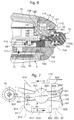
- the locking mechanism 8 has the function essential to lock and unlock some components of the device, as will be explained later. As we can see more particularly in Figures 2 and 7, it includes a rocker 80, a sliding cam 81 with inclined planes, a sliding stop 82 and a spring 83.
- the rocker 80 is pivotally mounted in the housing 140, along an axis 800 oriented radially in the middle 10 (fig. 7). Its circular middle part 801, in the center from which the axis 800 passes, carries two arms diametrically opposed 802 and 803. The arm 802 extends at its free end 804 to the vicinity of the push button 70. The arm 803 has at its free end a nose 805.
- Cam 81 is pivotally mounted by means of a tenon 811 crossing and riveted on the arm 802. Similarly, the stop 82 is pivotally mounted by means of a pin 821, crossing and riveted to the arm 803.
- the cam 81 has a shape general in parallelogram, with a large base 810 located on the axis 800 side, a small base 814, and two opposite sides 812 and 813 forming inclined planes and one ending in the vicinity of the ring 11, substantially at finger height 115, the other at finger height groove 135 which comprises the bottom 13. It will be noted that instead to be sliding, the cam 81 could for example be secured to the scale 80.
- the stop 82 is generally rectangular in shape with short sides 822 and 823 being one lower than finger 115, the other in throat region 135.
- the long side closest to the 800 axis is marked 824, the other reference 825.
- the spring 83 is produced by means of a flat wire folded and has two ends engaged in the housing 140 and positioned by the walls of this housing. It is provided with a boss 831 intended to cooperate with the nose 805.
- pawls 84 and 85 with springs 841 and 851 respectively are arranged in the case 1 to prevent retrograde rotation of the cassette 5 when it is not prevented by the mechanism 8. These pawls cooperate with one of the fingers 503 of the cassette in the groove 135 of the housing.
- timepiece 9 includes in particular a movement with quartz 90, a time-setting rod 92, a dial 93 and hands 94 and a battery 95.
- Movement 90 is housed in the opening 100 of the middle 10. It could it is also a mechanical movement.
- the dial 93 is integral with the movement 90 and positioned in the middle part 10 by the shoulder 108 ''.
- the pile is integrated into the watch movement.
- the disc 40 of the shutter 4 extends radially towards the periphery well beyond the movement 90.
- the battery 95 is engaged in the housing 109 of the middle 10, which is an extension of hole 139 bottom 13. Housing 109 and hole 139 are aligned on cutouts 401 or 402. In this way, stack 95 can be easily installed or removed when the cassette 5 is removed.
- the watch movement is not directly involved in the operation of the camera. However, it is not excluded provide for combined operation, for example using electronic circuits from the watch to control camera functions.
- the unit When the unit does not contain a cassette, its different parts are positioned as follows.
- the case 1 has only one moving part, namely the ring 11.
- the position it occupies is represented in the figure 1.
- the number "1" which it carries on its upper face, is aligned with objective 2. This indicates that the first photosensitive area of the film could be exposed if the device was fitted with a cassette.
- the ring 11 is prevented from turning counterclockwise in all circumstances, because of the spring 65 which cooperates with the toothing of wheel 614. Clockwise, it is prevented from turning by the action of jumper 64 ( Figure 3) between arming and shooting operations.
- the flip-flop 80 is in a so-called stop position, shown in solid lines in Figure 8.
- the arm 802 is at the level of push button 70, its end 804 being interposed between head 700 and the middle 10. In this way, it is not possible to operate the control mechanism 7. In other words, neither the ring 11 nor the pusher 70 cannot be actuated before a cassette is put in place. Note that at this stage finger 115 of ring 11 is not in the area shown in Figure 7, but further towards the left.
- the camera is thus ready for shooting.
- the arming mechanism 6 is armed, because of the manipulation that was performed after the last photo has been taken. This process will be described in more detail later.
- the device When the device is armed, one of the fingers 403 or 404 is in abutment against folding 726. To carry out a shooting, and after the camera has been oriented the object to be photographed, the operator presses the push button 70. It sinks into the middle 10 and causes the rocker 72.
- the mobile 71 is positioned so that the finger 722 of scale 72 can enter one of the cutouts 713.
- the outward movement of arm 725 of flip-flop 72 releases finger 403 or 404 from the shutter 4.
- the disc 40 then sets in motion in the direction of arrow A in figure 3, under the effect of the torque generated by the spiral spring 41.
- the cutout 401 sweeps the space located in the extension of the objective and allows light to pass for a short time, to impress the photosensitive film, in the area next to window 512.
- the disk 40 continues to run until one of the pins 407, 408 come up against one of the pins 625.
- the inertia of the gear train of the cocking mechanism 6 is sufficient for the mobile 62 to remain stationary despite the shock.
- the flip-flop 72 In its movement, the flip-flop 72 also drives the rocker 73 by its arm 725 which pushes the pad 731. The finger 732 of rocker 73 then raises the jumper 64. This last moves back under the effect of spring 66, pin 625 no longer being in contact with the bearing surface 643, but against the spout 642.
- the operator drives the ring 11 of 1/8 of a turn in a rotational movement in clockwise.
- the ring 11 rotates the mobile 61 which itself meshes with the mobile 62, the latter being in taken with the wheel 63.
- the wheel 63 is integral with shaft 131, it also rotates in the same direction and the same angle as the ring 11.
- the shaft 131 drives then the drive disc 53 and with it the film photosensitive 54.
- the wheel 621 of the mobile 62 turns 1/2 and also drives the gear 43 on a 1/2 turn, which arms the spiral spring 41.
- the pins 625 thus release the disc 40 from the shutter 4.
- the latter turns until one of the fingers 403 or 404 comes abut against folding 726.
- one of the pins 625 comes lean against support surface 643, move forward jumper 64 and arm spring 66.
- jumper 64 moved so that the wall of the oblong hole 641 come up against the foot 644, the ring 11 is then stopped in its movement and the device is armed to take a new shot.
- one of the numbers worn by the ring is opposite Objective 2, which thus serves as an index.
- the operator does not go to the end of the rotation, he does not will not be able to trigger the device until it has finished the maneuver. Indeed, the mobile 71, which is driven by the wheel 63, will be in a position such that finger 722 cannot penetrate into cutout 713 and consequently, the flip-flop 72 cannot function.
- both the ring 11 and the cassette 5 are always turned in the same direction of rotation.
- the manipulation is thus considerably simplified.
- the cover 52 occupies two different positions before and after exposure, it's very simple to distinguish a cassette blank of a used cassette, making it appear in window 512 a distinctive sign affixed to the cover 52.
- An arrow 525 is thus visible on the cassette 5 of FIG. 11, indicating that the film has not been exposed.
- a crossed circle 526 indicates that the cassette is worn, the film having been completely exposed because it did a full turn.
- Figure 12 represents the cassette during exposure, where the cutout 523 of the cover is located opposite window 512. The operator never sees this side of the cassette in this state.
Landscapes
- Physics & Mathematics (AREA)
- General Physics & Mathematics (AREA)
- Camera Bodies And Camera Details Or Accessories (AREA)
Priority Applications (1)
| Application Number | Priority Date | Filing Date | Title |
|---|---|---|---|
| EP98103103A EP0938023A1 (de) | 1998-02-23 | 1998-02-23 | Miniaturkamera und Kassette dazu |
Applications Claiming Priority (1)
| Application Number | Priority Date | Filing Date | Title |
|---|---|---|---|
| EP98103103A EP0938023A1 (de) | 1998-02-23 | 1998-02-23 | Miniaturkamera und Kassette dazu |
Publications (1)
| Publication Number | Publication Date |
|---|---|
| EP0938023A1 true EP0938023A1 (de) | 1999-08-25 |
Family
ID=8231464
Family Applications (1)
| Application Number | Title | Priority Date | Filing Date |
|---|---|---|---|
| EP98103103A Withdrawn EP0938023A1 (de) | 1998-02-23 | 1998-02-23 | Miniaturkamera und Kassette dazu |
Country Status (1)
| Country | Link |
|---|---|
| EP (1) | EP0938023A1 (de) |
Cited By (1)
| Publication number | Priority date | Publication date | Assignee | Title |
|---|---|---|---|---|
| WO2006077240A3 (fr) * | 2005-01-24 | 2007-03-15 | Christophe Claret S A | Piece d'horlogerie a cadran ouvert |
Citations (1)
| Publication number | Priority date | Publication date | Assignee | Title |
|---|---|---|---|---|
| US2625087A (en) * | 1949-05-12 | 1953-01-13 | Steineck Rudolf | Construction for cameras |
-
1998
- 1998-02-23 EP EP98103103A patent/EP0938023A1/de not_active Withdrawn
Patent Citations (1)
| Publication number | Priority date | Publication date | Assignee | Title |
|---|---|---|---|---|
| US2625087A (en) * | 1949-05-12 | 1953-01-13 | Steineck Rudolf | Construction for cameras |
Cited By (3)
| Publication number | Priority date | Publication date | Assignee | Title |
|---|---|---|---|---|
| WO2006077240A3 (fr) * | 2005-01-24 | 2007-03-15 | Christophe Claret S A | Piece d'horlogerie a cadran ouvert |
| US7420885B2 (en) | 2005-01-24 | 2008-09-02 | Christophe Claret S.A. | Timepiece provided with open dial plate |
| CH698500B1 (fr) * | 2005-01-24 | 2009-08-31 | Christophe Claret Sa | Pièce d'horlogerie à cadran muni d'une ouverture. |
Similar Documents
| Publication | Publication Date | Title |
|---|---|---|
| EP1373991B1 (de) | Chronograph mit zwei drehrichtungen | |
| EP2073076B1 (de) | Betätigungsmechanismus eines weckers | |
| EP3754436B1 (de) | Uhr, insbesondere taschenuhr, die mindestens mit einem deckel ausgestattet ist | |
| EP1959317A1 (de) | Mechanismus zur umschaltbaren Übertragung | |
| EP1513030A1 (de) | Uhr mit zwei relativ zueinander drehenden Uhrgehäusen | |
| CH705116B1 (fr) | Mécanisme de calendrier ayant des moyens d'entraînement et de correction pour deux indicateurs. | |
| EP2159652A1 (de) | Anzeigemechanismus für Uhr, der die Anzeige sowie das Ausblenden der aktuellen Uhrzeit ermöglicht | |
| CH706021B1 (fr) | Mouvement horloger du type chronographe à rattrapante et pièce d'horlogerie munie d'un tel mouvement. | |
| EP2238519B1 (de) | Uhr mit chronographie-mechanismus | |
| EP1058166B1 (de) | Weltzeituhr | |
| EP1962152A1 (de) | Schutzvorrichtung für Anzeige. | |
| FR2097126A1 (de) | ||
| EP3584643B1 (de) | Augenblicklich schaltende steuervorrichtung für datumsanzeige von uhren | |
| WO2015124510A1 (fr) | Mecanisme de sonnerie pour une piece d'horlogerie | |
| CH699794B1 (fr) | Dispositif d'aide au maintien en position d'un anneau indicateur de quantième pour pièce d'horlogerie. | |
| WO2009141262A1 (fr) | Mecanisme de piece d'horlogerie et module comprenant un tel mecanisme | |
| EP0938023A1 (de) | Miniaturkamera und Kassette dazu | |
| EP2281222B1 (de) | Anzeigevorrichtung | |
| EP1178373A1 (de) | Uhr | |
| CH708902A2 (fr) | Pièce d'horlogerie à animation. | |
| EP0938022A1 (de) | Miniaturkamera und Uhr mit einer solchen Kamera | |
| EP2615503B1 (de) | Steuermechanismus eines Federhaus für Uhrwerk | |
| EP2990880B1 (de) | Uhrwerk | |
| EP3486735A1 (de) | Uhrwerksmechanismus zur nullrückstellung der sekunde mit schneckennocken | |
| EP1316863A1 (de) | Formuhrwerk mit Chronograph |
Legal Events
| Date | Code | Title | Description |
|---|---|---|---|
| PUAI | Public reference made under article 153(3) epc to a published international application that has entered the european phase |
Free format text: ORIGINAL CODE: 0009012 |
|
| AK | Designated contracting states |
Kind code of ref document: A1 Designated state(s): AT BE CH DE DK ES FI FR GB GR IE IT LI LU MC NL PT SE |
|
| AX | Request for extension of the european patent |
Free format text: AL;LT;LV;MK;RO;SI |
|
| AKX | Designation fees paid | ||
| REG | Reference to a national code |
Ref country code: DE Ref legal event code: 8566 |
|
| STAA | Information on the status of an ep patent application or granted ep patent |
Free format text: STATUS: THE APPLICATION IS DEEMED TO BE WITHDRAWN |
|
| 18D | Application deemed to be withdrawn |
Effective date: 20000226 |