EP0938175A1 - Electrical distribution equipment - Google Patents
Electrical distribution equipment Download PDFInfo
- Publication number
- EP0938175A1 EP0938175A1 EP99200483A EP99200483A EP0938175A1 EP 0938175 A1 EP0938175 A1 EP 0938175A1 EP 99200483 A EP99200483 A EP 99200483A EP 99200483 A EP99200483 A EP 99200483A EP 0938175 A1 EP0938175 A1 EP 0938175A1
- Authority
- EP
- European Patent Office
- Prior art keywords
- tray
- rail system
- electrical components
- distribution equipment
- energy supply
- Prior art date
- Legal status (The legal status is an assumption and is not a legal conclusion. Google has not performed a legal analysis and makes no representation as to the accuracy of the status listed.)
- Withdrawn
Links
- 238000009434 installation Methods 0.000 claims abstract description 16
- 238000005265 energy consumption Methods 0.000 claims abstract description 3
- 238000010276 construction Methods 0.000 description 1
- 230000001419 dependent effect Effects 0.000 description 1
- 238000011161 development Methods 0.000 description 1
- 230000018109 developmental process Effects 0.000 description 1
- 239000011810 insulating material Substances 0.000 description 1
- 238000005192 partition Methods 0.000 description 1
- 238000005728 strengthening Methods 0.000 description 1
Images

Classifications
-
- H—ELECTRICITY
- H02—GENERATION; CONVERSION OR DISTRIBUTION OF ELECTRIC POWER
- H02B—BOARDS, SUBSTATIONS OR SWITCHING ARRANGEMENTS FOR THE SUPPLY OR DISTRIBUTION OF ELECTRIC POWER
- H02B1/00—Frameworks, boards, panels, desks, casings; Details of substations or switching arrangements
- H02B1/20—Bus-bar or other wiring layouts, e.g. in cubicles, in switchyards
- H02B1/202—Cable lay-outs
-
- H—ELECTRICITY
- H02—GENERATION; CONVERSION OR DISTRIBUTION OF ELECTRIC POWER
- H02B—BOARDS, SUBSTATIONS OR SWITCHING ARRANGEMENTS FOR THE SUPPLY OR DISTRIBUTION OF ELECTRIC POWER
- H02B1/00—Frameworks, boards, panels, desks, casings; Details of substations or switching arrangements
- H02B1/20—Bus-bar or other wiring layouts, e.g. in cubicles, in switchyards
- H02B1/205—Bus-bar or other wiring layouts, e.g. in cubicles, in switchyards for connecting electrical apparatus mounted side by side on a rail
Definitions
- the invention relates to distribution equipment for distribution of electrical energy from a power cable over an installation for energy consumption devices, comprising a tray having a base, side walls running parallel to one another and an energy supply and energy take-off side which run virtually perpendicularly to the side walls of the tray, an electrical rail system to be connected to the power cable and fixing means for one or more rows of electrical components which run parallel to the energy supply side of the tray, the input of which components can be electrically connected to the rail system and the output of which components can be electrically connected to the installation, in which the fixing means and the bottom faces of the electrical components are at a larger distance from the base of the tray than the upper faces of rails of the rail system, and in which rails of the rail system extend perpendicularly to the energy supply side of the tray and continues from said energy supply side as far as the last row of electrical components
- a so-called distribution box consists of a tray from insulating material, in which a vertical electrical supply rail system having current rails is accommodated. Said current rails could be connected by connections to components arranged in horizontal rows. The fixing means for the components lies higher than the rails.
- the current rails cover the whole base of the tray and for connecting the rails to the energy supply connecting bridges are used.
- the aim of the invention is to provide distribution equipment of the type mentioned in the preamble wherein the amount of wiring is reduced.
- a further aim of the invention is to create space for the wiring originating from the electrical components.
- Said aims are achieved according to the invention in that only one rail per energy supply phase is provided and that the distance between the outer side surfaces facing to the side walls of the tray of the two outer rails is smaller than the distance between the side walls of the tray.
- the rails are located in the middle of the tray.
- the assembly of the rails per energy supply phase is located below the components.
- the free space fixed to the rails, preferable at both sides thereof could be used for feeding through the wiring, so that an advantage both in space for the wiring and in the ease of wiring during installation.
- distribution equipment comprising a vertical rail system having three rails is known.
- the three rails are at the same distance as the electrical components from the bottom of the tray of the distribution equipment and consequently there is created no space for the wiring from the components.
- the fixing means for the electrical components comprise fixing strips fixed to the tray, which fixing strips are higher than the rail system with respect to the base of the tray.
- the distribution equipment according to the invention for the distribution of energy from a power cable is suitable as a consumer unit for a domestic installation. With this equipment outgoing groups for distribution of electrical energy are fused and connected to the mains power supply. To this end switch and fuse components are mounted in the consumer unit.
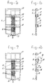
- the tray for the distribution equipment shown in Figures 1 and 2 consists of a base 1, with two adjoining side walls 2 and 3 running parallel to one another.
- the tray also has an energy supply side 4 and energy take-off side 5 which run virtually perpendicularly to the side walls 2 and 3 of the tray.
- the tray is provided in a conventional manner with fixing means for electrical components, the input of which can be electrically connected to a supply cable and the output of which can be electrically connected to an installation.
- the electrical components are arranged in at least one row, which row runs parallel to the energy supply side 4.
- a rail system which, for example, comprises three rails is provided for electrical connection of the electrical components, arranged in rows, to a power cable.
- the rail system extends perpendicularly to the energy supply side 4 of the tray.
- the rail system starts some distance away from the energy supply side and continues as far as the last row of electrical components.
- the connection between the inputs of the electrical components and the rail system and between said system and the power cable can be implemented in various ways.
- the amount of wiring which is needed to connect the electrical components to the power cable is drastically reduced.
- the inputs of the electrical components which are located in rows positioned at greater distances from the first row, counted from the energy supply side do not each have to be connected via a separate connection with, for example, a connector strip to the energy supply side to which the power cable is also connected.
- the electrical components are preferably fixed to fixing strips, for example hat-shaped rails, which themselves in turn can be fixed to the tray. Said fixing strips are mounted such that they are a greater distance away from the base of the tray than is the rail system.
- the wiring going from the electrical components to the installation can then be pulled through underneath the hat-shaped rails. Because the inputs of the electrical components in the rows located a greater distance away can be connected directly to the continuous rails of the rail system, space is created for the outgoing wiring from the components which are located closer to the energy supply side 4 of the tray.
- a frame as implementation of the inventive concept of the rail system, as a result of which it becomes possible to prepare an installation beforehand, at least prior to assembly of the distribution equipment on site.
- Said frame is preferably fixed to the tray by means of snap fastenings. Any connection or snap connection can be used and since said connections are obvious to a person skilled in the art these have not been shown.
- the frame shown in Figures 3 and 4 consists of the longitudinal sections 6 and 7 and the transverse end sections 8 and 9.
- the latter is also provided with a centre strip 10 and intermediate strips 11 and 12.
- the centre strip 10 is provided with a thicker rail system strip 13, in which the rails 14 of the rail system 15 have been accommodated such that they are insulated.
- the rails 14 are located in associated grooves 16 in the rail system strip 13 and are fixed therein, for example by means of clamping elements which are not shown.
- the transverse strips 11 and 12 are provided with supports 17, which have a predetermined height with respect to the transverse strips 11 and 12.
- 5 and 7 space 24 is reserved on the rail system strip (support) below the rails 14 for terminals for connecting the power supply for the domestic installation.
- the construction of the rail system per se can, for example, be implemented as is disclosed in British Patent 2 034 984.
- the rail system 15 continues as far as the uppermost hat-shaped rail 18.
- Said rail system is connected at the energy supply side 4 of the tray to the power cable in a manner which is not described in more detail.
- Said connection can, of course, also be made as is shown in British Patent 2 034 984 by means of a connecting cable.
- the electrical switching components mounted on the hat-shaped rails 18 can be connected at the supply side to the rail with the aid of cables in accordance with British Patent 2 034 984 or in another way.
- Figs 7 and 8 show that the connection between the input of the switching component 19 and the rail system 15 is made by means of an auxiliary rail system 20 running transversely to the rail system 15.
- the detailed implementation of the transverse rail can, for example, be reproduced after reading European Patent Applications 0 467 170 and 0 467 171.
- connection between the rail system and the auxiliary rail system can be implemented by means of cables or in some other way.
- a terminal strip 21 is mounted at the energy take-off side, to which terminal strip 21, on the one hand, the installation and, on the other hand, the outputs of the electrical components 19 can be connected for the connection between said outputs and the installation.
- the outgoing wiring thereof can be pulled through underneath the hat-shaped rails and terminated on the inside of the terminal strip.
- the advantage of the use of a vertical rail system 15 and a horizontal auxiliary rail system 20 is that components which do or do not have the means for connection to a horizontal rail can be used in arbitrary order.
- the side walls 2 and 3 can have been provided with break lines 22, by means of which the section 23 can be broken away so as to position two trays alongside one another without this also resulting in an inconvenient partition.
- the section 23 can be broken away so as to position two trays alongside one another without this also resulting in an inconvenient partition.
- two frames which can also be coupled to one another by means of long hat-shaped rails. After preparing the installation of the frames in advance, the latter can then be snapped home in their entirety into the coupled trays already installed on site.
Landscapes
- Engineering & Computer Science (AREA)
- Power Engineering (AREA)
- Details Of Indoor Wiring (AREA)
Abstract
Description
- The invention relates to distribution equipment for distribution of electrical energy from a power cable over an installation for energy consumption devices, comprising a tray having a base, side walls running parallel to one another and an energy supply and energy take-off side which run virtually perpendicularly to the side walls of the tray, an electrical rail system to be connected to the power cable and fixing means for one or more rows of electrical components which run parallel to the energy supply side of the tray, the input of which components can be electrically connected to the rail system and the output of which components can be electrically connected to the installation, in which the fixing means and the bottom faces of the electrical components are at a larger distance from the base of the tray than the upper faces of rails of the rail system, and in which rails of the rail system extend perpendicularly to the energy supply side of the tray and continues from said energy supply side as far as the last row of electrical components
- Distribution equipment of this type is disclosed in European Patent Application EP 0 466 043 A2.
- The known distribution equipment, a so-called distribution box consists of a tray from insulating material, in which a vertical electrical supply rail system having current rails is accommodated. Said current rails could be connected by connections to components arranged in horizontal rows. The fixing means for the components lies higher than the rails.
- The current rails cover the whole base of the tray and for connecting the rails to the energy supply connecting bridges are used.
- The aim of the invention is to provide distribution equipment of the type mentioned in the preamble wherein the amount of wiring is reduced.
- A further aim of the invention is to create space for the wiring originating from the electrical components.
- Said aims are achieved according to the invention in that only one rail per energy supply phase is provided and that the distance between the outer side surfaces facing to the side walls of the tray of the two outer rails is smaller than the distance between the side walls of the tray.
- Preferably the rails are located in the middle of the tray. By the configuration of the rows of electrical components and the rails of the rail system the amount of wiring which is needed to connect the components to the supply side is drastically reduced. The assembly of the rails per energy supply phase is located below the components. The free space fixed to the rails, preferable at both sides thereof could be used for feeding through the wiring, so that an advantage both in space for the wiring and in the ease of wiring during installation.
- It is observed that distribution equipment comprising a vertical rail system having three rails is known. However, the three rails are at the same distance as the electrical components from the bottom of the tray of the distribution equipment and consequently there is created no space for the wiring from the components.
- Preferably, the fixing means for the electrical components comprise fixing strips fixed to the tray, which fixing strips are higher than the rail system with respect to the base of the tray.
- The advantage achieved by this means is that space is created for the outgoing wiring from the rows of components located closer to the supply side.
- Further developments are described in the dependent claims.
- The invention will be explained in more detail below with reference to the drawing. In the drawing:
- Fig. 1 shows a tray for the distribution equipment according to the invention;
- Fig. 2 shows a side view of the tray in Fig. 1;
- Fig. 3 shows the top view of a frame for the distribution equipment according to the invention;
- Fig. 4 shows a side view of the frame in Fig. 3;
- Fig. 5 shows the frame in Fig. 3 that has been provided with hat-shaped rails for fixing electrical components;
- Fig. 6 shows the side view of the frame in Fig. 5;
- Fig. 7 shows a frame according to the invention in which a vertical and a horizontal rail system have been used;
- Fig. 8 shows the side view of the frame according to Fig. 7.
-
- The distribution equipment according to the invention for the distribution of energy from a power cable is suitable as a consumer unit for a domestic installation. With this equipment outgoing groups for distribution of electrical energy are fused and connected to the mains power supply. To this end switch and fuse components are mounted in the consumer unit.
- The tray for the distribution equipment shown in Figures 1 and 2 consists of a base 1, with two
adjoining side walls 2 and 3 running parallel to one another. The tray also has an energy supply side 4 and energy take-off side 5 which run virtually perpendicularly to theside walls 2 and 3 of the tray. - The tray is provided in a conventional manner with fixing means for electrical components, the input of which can be electrically connected to a supply cable and the output of which can be electrically connected to an installation. The electrical components are arranged in at least one row, which row runs parallel to the energy supply side 4.
- A rail system which, for example, comprises three rails is provided for electrical connection of the electrical components, arranged in rows, to a power cable. The rail system extends perpendicularly to the energy supply side 4 of the tray. The rail system starts some distance away from the energy supply side and continues as far as the last row of electrical components. The connection between the inputs of the electrical components and the rail system and between said system and the power cable can be implemented in various ways.
- As a result of the use of the continuous "vertical" rail system, the amount of wiring which is needed to connect the electrical components to the power cable is drastically reduced. After all, the inputs of the electrical components which are located in rows positioned at greater distances from the first row, counted from the energy supply side, do not each have to be connected via a separate connection with, for example, a connector strip to the energy supply side to which the power cable is also connected.
- The electrical components are preferably fixed to fixing strips, for example hat-shaped rails, which themselves in turn can be fixed to the tray. Said fixing strips are mounted such that they are a greater distance away from the base of the tray than is the rail system. The wiring going from the electrical components to the installation can then be pulled through underneath the hat-shaped rails. Because the inputs of the electrical components in the rows located a greater distance away can be connected directly to the continuous rails of the rail system, space is created for the outgoing wiring from the components which are located closer to the energy supply side 4 of the tray.
- It is also advantageous to use a frame as implementation of the inventive concept of the rail system, as a result of which it becomes possible to prepare an installation beforehand, at least prior to assembly of the distribution equipment on site. Said frame is preferably fixed to the tray by means of snap fastenings. Any connection or snap connection can be used and since said connections are obvious to a person skilled in the art these have not been shown.
- The frame shown in Figures 3 and 4 consists of the
longitudinal sections 6 and 7 and thetransverse end sections intermediate strips rail system strip 13, in which therails 14 of therail system 15 have been accommodated such that they are insulated. Therails 14 are located in associatedgrooves 16 in therail system strip 13 and are fixed therein, for example by means of clamping elements which are not shown. Thetransverse strips supports 17, which have a predetermined height with respect to thetransverse strips space 24 is reserved on the rail system strip (support) below therails 14 for terminals for connecting the power supply for the domestic installation. - The way in which the
supports 17 are provided withfixing strips 18 in the form of conventional hat-shaped rails can be seen in Figs. 5 and 6. - It is also pointed out that although the rail system is arranged in the middle of the frame said rail system can, of course, also be located away from the middle of said frame.
- Of course, it is also possible to fix more than two hat-
shaped rails 18 on the frame by means of a corresponding number ofsupports 17. - The construction of the rail system per se can, for example, be implemented as is disclosed in
British Patent 2 034 984. - As can be seen from Figures 2 - 8, the
rail system 15 continues as far as the uppermost hat-shaped rail 18. Said rail system is connected at the energy supply side 4 of the tray to the power cable in a manner which is not described in more detail. Said connection can, of course, also be made as is shown inBritish Patent 2 034 984 by means of a connecting cable. - The electrical switching components mounted on the hat-
shaped rails 18 can be connected at the supply side to the rail with the aid of cables in accordance withBritish Patent 2 034 984 or in another way. - Figs 7 and 8 show that the connection between the input of the
switching component 19 and therail system 15 is made by means of anauxiliary rail system 20 running transversely to therail system 15. The detailed implementation of the transverse rail can, for example, be reproduced after reading European Patent Applications 0 467 170 and 0 467 171. - It is also pointed out that the connection between the rail system and the auxiliary rail system can be implemented by means of cables or in some other way.
- A
terminal strip 21 is mounted at the energy take-off side, to whichterminal strip 21, on the one hand, the installation and, on the other hand, the outputs of theelectrical components 19 can be connected for the connection between said outputs and the installation. For the electrical components arranged in a row located further away from theterminal strip 21, the outgoing wiring thereof can be pulled through underneath the hat-shaped rails and terminated on the inside of the terminal strip. - The advantage of the use of a
vertical rail system 15 and a horizontalauxiliary rail system 20 is that components which do or do not have the means for connection to a horizontal rail can be used in arbitrary order. - As can be seen from Figs 1 and 2, the
side walls 2 and 3 can have been provided withbreak lines 22, by means of which thesection 23 can be broken away so as to position two trays alongside one another without this also resulting in an inconvenient partition. In this case it is then possible to use two frames, which can also be coupled to one another by means of long hat-shaped rails. After preparing the installation of the frames in advance, the latter can then be snapped home in their entirety into the coupled trays already installed on site.
Claims (9)
- Distribution equipment for distribution of electrical energy from a power cable over an installation for energy consumption devices, comprising a tray having a base, side walls running parallel to one another and an energy supply and energy take-off side which run virtually perpendicularly to the side walls of the tray, an electrical rail system to be connected to the power cable and fixing means for one or more rows of electrical components which run parallel to the energy supply side of the tray, the input of which components can be electrically connected to the rail system and the output of which components can be electrically connected to the installation, in which the fixing means and the bottom faces of the electrical components are at a larger distance from the base of the tray than the upper faces of rails of the rail system, and in which rails of the rail system extend perpendicularly to the energy supply side of the tray and continues from said energy supply side as far as the last row of electrical components, characterised in that only one rail per energy supply phase is provided and that the distance between the outer side surfaces facing to the side walls of the tray of the two outer rails is smaller than the distance between the side walls of the tray.
- Distribution equipment according to claim 1, characterised in that the rails are located in the middle of the tray.
- Distribution equipment according to Claim 1 or 2, chacterised in that the fixing means for the electrical components comprise fixing strips fixed to the tray, which fixing strips are higher than the rail system with respect to the base of the tray.
- Distribution equipment according to Claim 1, 2 or 3, characterised in that an auxiliary rail system running perpendicularly to the rail system is added to at least one row of electrical components for connection of the inputs of the electrical components of the row concerned to the rail system.
- Distribution equipment according to Claim 3 or 4, characterised in that the tray is provided with a frame fixed therein, which frame is provided with a rail system strip running perpendicularly to the energy supply side, in which rail system strip the rail system is accommodated such that it is electrically insulated, and with supports for the fixing strips for the electrical components, the top face of which is higher than the rail system.
- Distribution equipment according to Claim 5, characterised in that the rail system strip is located in the middle of the frame.
- Distribution equipment according to one of the preceding claims, characterised in that the side walls of the tray are provided with break lines for breaking away at least one section of the side wall.
- Distribution equipment according to one of the preceding claims, characterised in that a terminal strip is mounted close to the energy take-off side of the tray, to which terminal strip the electrical components and the installation are connected to connect these to one another.
- Frame suitable for use in distribution equipment according to one of the preceding claims.
Applications Claiming Priority (2)
| Application Number | Priority Date | Filing Date | Title |
|---|---|---|---|
| NL1008374 | 1998-02-20 | ||
| NL1008374A NL1008374C2 (en) | 1998-02-20 | 1998-02-20 | Distribution device for distribution of electrical energy over an installation. |
Publications (1)
| Publication Number | Publication Date |
|---|---|
| EP0938175A1 true EP0938175A1 (en) | 1999-08-25 |
Family
ID=19766587
Family Applications (1)
| Application Number | Title | Priority Date | Filing Date |
|---|---|---|---|
| EP99200483A Withdrawn EP0938175A1 (en) | 1998-02-20 | 1999-02-19 | Electrical distribution equipment |
Country Status (2)
| Country | Link |
|---|---|
| EP (1) | EP0938175A1 (en) |
| NL (1) | NL1008374C2 (en) |
Cited By (2)
| Publication number | Priority date | Publication date | Assignee | Title |
|---|---|---|---|---|
| EP1983622A1 (en) | 2007-04-20 | 2008-10-22 | Siemens Aktiengesellschaft | Installation distributer with busbar modules |
| CN104184050A (en) * | 2013-05-22 | 2014-12-03 | 尼克尔有限责任公司 | Distribution strip |
Citations (3)
| Publication number | Priority date | Publication date | Assignee | Title |
|---|---|---|---|---|
| EP0063970A1 (en) * | 1981-04-22 | 1982-11-03 | Merlin Gerin | Power bus set for a modular apparatus of an electrical box |
| EP0466043A2 (en) * | 1990-07-09 | 1992-01-15 | ABBPATENT GmbH | Distribution installation with at least two rows of electrical apparatus of a narrow type |
| WO1992014289A1 (en) * | 1991-02-08 | 1992-08-20 | Fibox Oy Ab | Enclosure for miniature circuit breakers |
-
1998
- 1998-02-20 NL NL1008374A patent/NL1008374C2/en not_active IP Right Cessation
-
1999
- 1999-02-19 EP EP99200483A patent/EP0938175A1/en not_active Withdrawn
Patent Citations (3)
| Publication number | Priority date | Publication date | Assignee | Title |
|---|---|---|---|---|
| EP0063970A1 (en) * | 1981-04-22 | 1982-11-03 | Merlin Gerin | Power bus set for a modular apparatus of an electrical box |
| EP0466043A2 (en) * | 1990-07-09 | 1992-01-15 | ABBPATENT GmbH | Distribution installation with at least two rows of electrical apparatus of a narrow type |
| WO1992014289A1 (en) * | 1991-02-08 | 1992-08-20 | Fibox Oy Ab | Enclosure for miniature circuit breakers |
Cited By (6)
| Publication number | Priority date | Publication date | Assignee | Title |
|---|---|---|---|---|
| EP1983622A1 (en) | 2007-04-20 | 2008-10-22 | Siemens Aktiengesellschaft | Installation distributer with busbar modules |
| DE102007018826A1 (en) | 2007-04-20 | 2008-10-30 | Siemens Ag | Distribution boards with busbar modules |
| DE102007018826B4 (en) * | 2007-04-20 | 2009-12-24 | Siemens Ag | Distribution boards with busbar modules |
| CN104184050A (en) * | 2013-05-22 | 2014-12-03 | 尼克尔有限责任公司 | Distribution strip |
| CN104184050B (en) * | 2013-05-22 | 2017-04-12 | 尼克尔有限责任公司 | distribution strip |
| US9728918B2 (en) | 2013-05-22 | 2017-08-08 | Knuerr Gmbh | Distribution strip |
Also Published As
| Publication number | Publication date |
|---|---|
| NL1008374C2 (en) | 1999-08-24 |
Similar Documents
| Publication | Publication Date | Title |
|---|---|---|
| US10951027B2 (en) | Smart load center panel | |
| KR102595685B1 (en) | Module type bus bar branch device | |
| JPH0787648B2 (en) | Gas insulated switchgear | |
| US5995362A (en) | Support and electrical power supply device for electrical switchgear | |
| CA1110354A (en) | Control center bus bars | |
| FI943780A0 (en) | Device for supplying electrical energy to at least one electrical installation device | |
| CA2064510A1 (en) | Power distribution apparatus | |
| US5326933A (en) | Electrical installation system | |
| JP4385574B2 (en) | Distribution board device | |
| EP0938175A1 (en) | Electrical distribution equipment | |
| EP0055094A2 (en) | Gas-insulated substations | |
| US4868981A (en) | Method of making loop-feed wiring arrangement for electric circuit breakers and switches | |
| US3787713A (en) | Service section switchboard with horizontally extending bus bar stack and means for mounting some circuit breakers with load terminals facing vertical wiring trough and other circuit breakers with load terminals facing horizontal wiring trough | |
| JP2000188805A (en) | Connection conductor device for distribution board | |
| JPH0564323A (en) | DC substation | |
| EP0319483B1 (en) | Modular low-voltage electrical panel for modular electrical apparatus | |
| US7859838B2 (en) | Arrangement for placing a frequency converter in a cabinet | |
| EP0836259B1 (en) | Electrical installation unit | |
| CN223218664U (en) | Inlet wire contact cabinet, reactive compensation cabinet, feeder line cabinet and low-voltage power distribution module | |
| CN108879345B (en) | Wiring structure of switch cabinet | |
| CN1033716A (en) | Prefabricated medium-voltage switchgear cabinet with rotary switch | |
| AU731006B2 (en) | EIB device for insertion in an installation box | |
| RU2199174C2 (en) | Switchgear installation | |
| US5070428A (en) | Encapsulated switching system with longitudinal coupling of bus bars, inner partitions, and coupling fields | |
| SU1615833A1 (en) | All-inclusive distributor device |
Legal Events
| Date | Code | Title | Description |
|---|---|---|---|
| PUAI | Public reference made under article 153(3) epc to a published international application that has entered the european phase |
Free format text: ORIGINAL CODE: 0009012 |
|
| AK | Designated contracting states |
Kind code of ref document: A1 Designated state(s): AT BE CH DE DK ES FI FR GB GR IE IT LI NL PT SE |
|
| AX | Request for extension of the european patent |
Free format text: AL;LT;LV;MK;RO;SI |
|
| 17P | Request for examination filed |
Effective date: 20000224 |
|
| AKX | Designation fees paid |
Free format text: AT BE CH DE DK ES FI FR GB GR IE IT LI NL PT SE |
|
| RAP1 | Party data changed (applicant data changed or rights of an application transferred) |
Owner name: EATON ELECTRIC N.V. |
|
| RAP1 | Party data changed (applicant data changed or rights of an application transferred) |
Owner name: EATON ELECTRIC B.V. |
|
| STAA | Information on the status of an ep patent application or granted ep patent |
Free format text: STATUS: THE APPLICATION IS DEEMED TO BE WITHDRAWN |
|
| 18D | Application deemed to be withdrawn |
Effective date: 20060901 |