EP0938844A1 - Brezelschlingsystem - Google Patents
Brezelschlingsystem Download PDFInfo
- Publication number
- EP0938844A1 EP0938844A1 EP99103614A EP99103614A EP0938844A1 EP 0938844 A1 EP0938844 A1 EP 0938844A1 EP 99103614 A EP99103614 A EP 99103614A EP 99103614 A EP99103614 A EP 99103614A EP 0938844 A1 EP0938844 A1 EP 0938844A1
- Authority
- EP
- European Patent Office
- Prior art keywords
- dough
- strand
- molding
- axis
- dough strand
- Prior art date
- Legal status (The legal status is an assumption and is not a legal conclusion. Google has not performed a legal analysis and makes no representation as to the accuracy of the status listed.)
- Granted
Links
Images


Classifications
-
- A—HUMAN NECESSITIES
- A21—BAKING; EDIBLE DOUGHS
- A21C—MACHINES OR EQUIPMENT FOR MAKING OR PROCESSING DOUGHS; HANDLING BAKED ARTICLES MADE FROM DOUGH
- A21C3/00—Machines or apparatus for shaping batches of dough before subdivision
- A21C3/08—Machines for twisting strips of dough, e.g. for making pretzels
Definitions
- the invention relates to a method for the mechanical production of pretzel blanks, using multiple pretzel formers, each in one position for receiving a strand of dough from a common strand of dough feed device and in a distant position to dispense the molded one Pretzel blanks can be moved to a common discharge device. While the transfer from the receiving position to the delivery position is carried out in each molding unit the recorded strand of dough is shaped into a pretzel blank and then attached to the Transfer the discharge device.
- the invention further relates to an arrangement for mechanical pretzel production, which is used to carry out the method mentioned is suitable and has several mold units that are used to process a Dough strands are formed into a pretzel blank.
- the molding units are on arranged a common chassis and can be used for Output of a feed device for dough strands or to the input of a discharge device for pretzel blanks to be moved.
- a drive motor By means of a drive motor the moving frame between the feed and discharge device is movably guided.
- the invention relates to a feed device simultaneously in the function as Bending and length measuring device for dough strands for use in the above Arrangement.
- the invention further relates to a molding unit which is used in said method or said arrangement executed and with a Form table is provided, the support saddle for supporting the middle section Has U-shaped curved dough strands.
- the molding unit further comprises a sling device that is rotatable relative to the molding table and on the molding table foldable and swivel mounted and for the two end sections of the U-shaped Dough strand is provided with a gripping member. They can do that protrude from the molding table extending end dough strand sections or intervention.
- the invention relates to a gripping member for said molding unit, which has two jaws, which by means of a drive unit and adjustable to each other for clamping and releasing dough.
- a method and an arrangement for pretzel formation results from the publication 1 288 532 of the German Patent Office.
- a dough strand in a pretzel molding device is the mold issued by a U, with a central arch that has two straight, freely ending Thigh connects. These are pressed in in a further manufacturing step or bent together, on opposite sides Places that between the central arch and the free ends of the legs ( ⁇ shape).
- the bent legs are then about Twisted or swallowed 360 °, the swallowing of the legs at the previously indented points.
- the legs with the twisted Places are then swiveled or folded onto the middle sheet, and the free ones Leg ends pressed onto the middle arch and glued.
- the form units on the circumference of the jacket are always one arranged in the same direction rotating drum.
- the strand of dough is from transferred to a feed device in the molding unit, to the pretzel blank molded and then thrown out of the molding unit, being on a Discharge device comes to rest with the side down on which the free Leg ends are pressed or glued.
- the angular velocity of the mold units on the Outer jacket carrying drum are started up, but the Pieces of dough are exposed to a rapidly increasing centrifugal force. This can to fly out and deform the strand of dough as well as undesirable Inaccuracies in the shape of the pretzel blank result.
- the travel time of the mold units between the feed and discharge station depending on the Speed and in particular the radius of the molding units on the outer jacket carrying travel drum. This is intended to increase many mold units the production speed, the radius of the Travel drum and thus the dead time of the molding units on the way from the Laxative to the feeding station can be increased. This reduces the load on the individual Molding units and thus the overall efficiency of the pretzel sling machine.
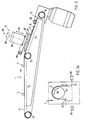
- FIG. 7 there is a vertically adjustable molding table disclosed as a mounting plate 15 with hanging saddle.
- the vertical adjustability Serves to control a light barrier 16, which then has a closing signal for gripping the strand for a gripper at a defined distance from Strand end generated.
- the vertical movement of the receiving plate 15 upwards is ended in a predetermined position in which the dough strand is a target length Has.
- DE-C-41 05 254 describes a device for looping a pretzel from a straight dough strand of defined length can be seen.
- a molding table with several, running side by side, different wide conveyor belts revealed.
- a hanging saddle jumps between them for the dough strand forming marks 40 upwards.
- these application marks 40 can again be sunk down by means of a pneumatic cylinder 42, so without hindrance the finished looped pretzel 29 can be removed.
- a gripper with two clamping jaws (cf. numbers 36, 36 'in the figure there 4a and 4b) used.
- the gripper is provided with a presser 37 which is between the two jaws 36, 36 'of the gripper in the vertical direction is around the stepped end of the dough strand to the one below Press section of the middle part of the U-shaped curved dough strand.
- This gripper corresponds to the gripping element mentioned at the beginning.
- DE-A-44 32 162 discloses a pretzel molding station in which the molding process in a forming station by means of rotation about a central axis, the dough strand is fed from a conveyor station.
- one free rotatable disc (reference number 5 there) to be used during a feed of a working belt lies on this.
- the freely rotatable one Disc 5 causes the deformation of the strand of dough and is by a piston rod 7 from an initial position shown in FIG. 2 to a position shown there Figure 3 shown end position.
- a pretzel slinging machine is known from DE-U-296 20 893, in which a forming and prepositioning station to form the U-shape from a strand of dough (local reference number 2) is arranged and a liftable from a conveyor belt and has a positioning disk 22 which can be placed thereon, with which the Dough strand is given the U shape.
- the solution is the manufacturing method characterized in the attached claim 1 and the manufacturing arrangement characterized in claim 8 suggested for pretzel blanks.
- Another advantage that can be achieved with the invention is that with the almost minimal number of two mold units an extremely fast dough strand removal processing can be performed while after closest prior art due to limited drum speed Increasing efficiency far more than two molding units can be used would have, but on the other hand, a complicated control construction and leads to high equipment and parts costs, combined with an increase in Probability of failure.
- a synchronous mode of operation of the two is expedient within the scope of the invention related shape units, what with gear and belt transmission and a single drive motor or a plurality of drive motors could be achieved via a bus system and a "electronic gear" are coordinated.
- the use of only one Motors has the advantage that collisions between moving in the event of failure Make parts easier to avoid.
- the particularly advantageous is the production speed accelerating possibility opens up the looping of the Dough strand ends around the first axis and pivoting or folding the same around the second axis on the middle section of the dough strand simultaneously and / or perform on top of each other.
- the molding unit is satellite-like can be moved around the axis of rotation of the drum, which is parallel to the swivel or Folding axis of the dough strand ends runs, according to an advantageous invention departed from it: the common axis of symmetry of motion for the mold units runs perpendicular to the second pivot axis as well as at an angle or perpendicular to the first mentioned wrap axis for the dough strand ends.
- the common axis perpendicular to the Swiveling and folding axis runs, by means of which the dough strand ends on the Dough strand middle part is prevented that high movement or convert positioning speeds for the forming units into centrifugal forces, which throw the dough strands out of the molding units.
- the arrangement of the mold units on the moving frame according to the invention enables it, a strand of dough that has been looped to the pretzel blank to the discharge device dispense while the other molding device is a U-shaped Receives strand of dough from a conveyor of the feed device.
- the other molding device is a U-shaped Receives strand of dough from a conveyor of the feed device.
- Pretzel blank manufacturing arrangement takes the one molding device a strand of dough while complementary to her or in The second shaping device, which works in push-pull mode, is used to dispense the finished molded part Pretzel blanks located on the discharge device.
- the feasibility of this push-pull operation promotes when the molding units are point symmetrical to each other whenever possible.
- the point of symmetry can be the symmetry and rotation axis of a rotatable bogie run on which the mold units are arranged.
- this axis of rotation runs vertically and / or perpendicularly to any one common level of the molding unit and / or to one of the molding unit for the dough strand end sections realized wrap and / or fold-over axis.
- the undesirable ones mentioned above can advantageously be used Avoid centrifugal effects.
- the reproduction accuracy for the shape of the pretzel blanks and the dough protection can be with an advantageous embodiment of the invention increase even further that the feed and discharge devices as well as the molding units with adjoining each other in the uptake or discharge position Conveyor belts are realized. From one conveyor belt to the other Dough strand or the pretzel blank gently and without vibrations or damage be handed over.
- the feeding device with a strand length measuring unit and a strand bending unit provided for the symmetrical alignment of the dough strands a U-shape are operatively connected.
- a dough strand ejection organ for example a conveyor belt that can be controlled in two directions, expedient.
- the direction of this ejection conveyor can be from the strand length measuring unit, which in conjunction with a control or computing unit the measured strand length with entered length specifications and compares geometries.
- bending and Length measuring device used feed device for use in the invention Arrangement is suitable. This can be advantageous before looping positioning of the strand of dough by means of a rotatably driven one Richtrades take place on which a strand of dough moved on a conveyor belt Facility is coming. Then the dough strand is turned into a by means of the straightening wheel Directed until one end of the dough passes a detection sensor that triggers a signal defining a first end position. Then the straightening bike with the adjacent strand of dough turned in the other direction until the other end of the dough strand can respond to another sensor, whereby a signal defining a second end position is triggered.
- the signals are a control device supplied to the drive motor for the straightening wheel controlled.
- the straightening wheel is half of its total Angle of rotation between the two end positions of the two ends of the dough strand turned back, whereby a symmetrical U-shape is formed and to the Molding unit can be passed.
- the output side with the control unit is connected, which is the drive motor of the straightening wheel for realizing the two Controlled end positions and the symmetrical middle position.
- a molding unit is also used with the features mentioned in the invention proposed that the form table in its distance or its height in relation to the looping device is adjustable, and the actuation of the gripping members each recognition sensors associated with a strand of dough is activated if these each on the removal of one of the dough strand ends in the course of the adjustment the distance or the height of the molding table.
- the previously measured in the feed device according to the invention Length of dough to vary the distance between those hanging from the forming table Ends of the U-shaped dough strand and the gripping members used become.
- the Measurement is preferably carried out with the aid of a computing and / or control unit.
- the determined length of the dough strand can be used to optimize the position of the gripping members compared to the ends of the dough by varying the position of the shaping table be used via its drive.
- the distance further the geometric dimensions of the molding table or the gripping organs.
- Forming unit By measuring the strand of dough the feeder and adjusting the distance of the molding table with the Dough strand ends to the gripping members, it is possible in the invention Forming unit to loop dough strands of different lengths into pretzels. Come here after the looping process the dough strand ends not to be placed on Overhang or even overhang beyond the middle part of the dough strand.
- the dough strand is hung from the shaping table, and the dough strand end sections or U-legs, over which the gripping members Protruding the edge of the form table.
- the distance between The ends of the dough strand and the gripping members vary until the ends of the dough strand can be optimally grasped by the gripping organs.
- the loop of the Dough strand ends preferably through 360 °, are carried out by a first looping axis, whereby the ends of the dough strand or U-legs are crossed.
- the U-dough strand can be used in the further pretzel looping be left in the same mold. Dough strand and pretzel shape deforming and deforming transfer steps are avoided.
- the Rotation of the gripping member around the first looping axis causes the looping of the dough strand and the rotation around the second pivot axis works Dough strand ends on the middle part of the dough strand. It is particularly advantageous it when the two looping and folding axes are perpendicular to each other.
- the rejection of incompletely shaped pretzels can be arranged considerably reduce and also significantly increase the quality of pretzel production.
- the bogie with the two mold units preferably by 180 ° by one diagonally or perpendicular to the looping or folding axis of the gripping organ assembly arranged movement axis formed.
- Due to the bogie insert for the molds are a matter of course other arrangements of feed and discharge devices than possible in a direction opposite to each other.
- the feed and discharge devices in one be arranged at right angles to each other, the bogie then reversing executes a rotation angle of 90 ° or 270 ° instead of 180 ° each.
- Feed and discharge device are arranged opposite one another. So can two opposing molding devices also work in push-pull and complement each other. While the one molding unit pulls a strand of dough from the Receiving feeder, the other molding unit passes a finished looped Pretzel blank to the discharge device.
- An opposite Arrangement of feed and discharge device also facilitates the construction and the Execution of the arrangement of the molding units on the traversing, in particular Bogie.
- FIG. 1 are related to the pretzel sling machine according to the invention the transport and conveying direction 1 for transverse strands of dough 2, U-shaped Dough strands 3, ⁇ -shaped dough strands 4, closed loop dough pieces 5 and Completely formed pretzel blanks 6 following machine units in a row arranged: feed device 7 with straightening unit 8, bogie 9 with a first molding unit 10 and a second molding unit 11, and a discharge device 12.
- the straightening unit 8 also points a sensor system 82 for detecting the leg ends 31 of the U-shaped dough strand 2 on; by turning the strand of dough back and forth by means of the straightening wheel 81 in connection with a (not) drawn control and computing unit achieve a symmetrical alignment of the U-shaped dough strand 3, as with Process step b) designated.
- a sensor system 82 for detecting the leg ends 31 of the U-shaped dough strand 2 on; by turning the strand of dough back and forth by means of the straightening wheel 81 in connection with a (not) drawn control and computing unit achieve a symmetrical alignment of the U-shaped dough strand 3, as with Process step b) designated.
- the next process step of dough processing is by means of the molding unit 10, 11, which is currently in contact with the feed device 7, gives the U-shaped dough strand a shape that forms the ⁇ -shaped dough strand 4 leads with spread end portions 41 (method step c).
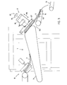
- the top of the feed conveyor belt carrying the dough strands 2, 3 settles 71 from a largely horizontal section 72 and one inclined section 74 inclined toward the outlet 73 of the conveyor device.
- the straightening device 8 with the straightening wheel 81 is arranged within the latter, which is perpendicular to the inclined section 74 Axis of rotation 83 can be set in reciprocating rotations 84.
- You can also the straightening unit 8 including the straightening wheel 81 landing and lifting movements 85 are issued so that a U-shaped and symmetrically aligned Dough strand 3 below the straightening wheel 81 through to the exit 73 of the Conveyor can get.
- the up and down movement 85 can also be performed with a swiveling movement Realize pivot plate 87 which is articulated via a pivot axis 88.
- the straightening wheel 81 is one frustoconical beveled or tapered outer circumference.
- the taper increases with increasing distance from the conveyor belt 71.
- a dough strand 2 to be positioned is slightly raised by the straightening wheel, so that Frictional forces between the conveyor belt 71 and the dough strand 2, 3 reduced become. So that the advantage is achieved that the dough strand is lighter and therefore faster is aligned on the conveyor belt 71 and also deformation-free remains. Furthermore, the dough strand is prevented from being pulled under the straightening wheel 81 becomes.
- the inclined section also contributes to reducing the frictional forces 74 of the conveyor belt 71, the second and third conveyor rollers 75, 76 is defined.
- the horizontal section 72 already mentioned is from the first Conveyor roller 77 and the second conveyor roller 75 defined.
- the control or computing unit one turn of the straightening wheel 81 now clockwise until the other End of dough strand or leg end 31 interrupts the sensor system or light barrier 82, which thereupon with the generation of a further sensor signal to the control or arithmetic unit.
- the first turn counterclockwise served to establish the reference.
- the control and computing unit needs in connection with an angle counter to drive the drive means 86 only so far that the ends of the dough 31 only cover the path x / 2, which is half of the total Angle of rotation between the two signal-triggering positions of the ends of the dough 31 corresponds.
- the straightening wheel 81 is now moved upward, for example offset about the pivot axis 88 in the lifting movement 85.
- an ejection conveyor belt 15, which is between the feed device 7 and the bogie 9 with the two molding units 10, 11 can be arranged according to a special embodiment of the invention. This can be reversed in its conveying direction 151 by drive means, not shown. If the dough strands are too short or too long, the conveying direction 15 becomes so set that dough strands 3 to the ejection gap 152 between the conveyor belt 71 of the feed device 7 and the lower ejection conveyor belt 15 can be transported. If the dough strand lengths are within tolerance, the direction of the ejection conveyor set so that falling U-shaped Dough strands 3 taken over by the straightening unit 8 or the feeding device 7 are and transported to the bogie 9 with the molding units 10, 11 can be.
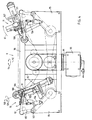
- the bogie 9 is on a pivot bearing 91 about an axis of rotation 92 by means of a drive motor 93, preferably reversing or alternating Directions of the rotary movements 94 arranged movably.
- a drive motor 93 preferably reversing or alternating Directions of the rotary movements 94 arranged movably.
- On respective End walls 95 are the first molding unit 10 and the second molding unit 11 with respect to a plane running through the axis of rotation 92 (perpendicular to the plane of the drawing the figure 4) opposite and articulated adjustable.
- the first molding unit 10 is currently opposite in the receiving position the feeder, while being symmetrical with respect to said plane opposing molding unit 11 is just in the dispensing position the discharge device (12 in Figure 1).
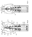
- the two mold units 10, 11 are each with one Forming table 101 provided on the respective end wall 95 via a (perpendicular to the plane of the drawing) pivot axis 102 is articulated.
- the Pivot 103 of the molding table 101 can be moved in and out linearly cause extendable swivel cylinder 104, the one hand against the end wall 95 of the bogie 9 and on the other hand against the side wall 105 of the molding table 101 is supported.
- the pivot axis 102 is opposite to that Top of the molding table 101 is shifted so far down that the free end edge 106 of the molding table 101 in its swivel path with respect to a plane largely tangential, that of the depending leg end sections 31 of the U-shaped dough strand 3 clamped on the forming table 101 is. This ensures that when pivoting 103 of the molding table 101st the leg end portions 31 of the U-shaped dough strand 3 are only minimally deflected and in particular are not pivoted out of the sling device 107, another essential component of the respective molding unit 10, 11 forms.
- a folding axis 108 which is approximately parallel to the pivot axis 102 of the molding table 101 extends either into a position below the edge of the molding table 106 is pivoted (see the position of the first molding unit in FIG. 4) 10 to the left of the axis of rotation 92) or in the direction of the top of the molding table 101 can be folded (cf. the position of the second molding unit 11 on the right the axis of rotation 92 in Figure 4). In the latter position, the sling device closes 107 with the forming table 101 an acute angle, the above Process step e) - pressing the leg ends 31 onto the middle part of the dough strand 32 - is carried out.
- the folding axis 108 corresponds to that in FIG Figure 1, process step e) shown folding axis 62 for completing the pretzel blank 6.
- the position of the first molding unit 10 (in Figure 4 to the left of the axis of rotation 92) corresponds to process steps b) or c) shown in FIG.
- the two identically constructed molding units 10, 11 are over a supporting structure 96 of the rotating unit 9 is connected to one another in such a way that when it rotates 94 of the bogie 9 both like satellites about the bogie axis of rotation 92 circles.
- the first molding unit 10 while this from the receiving position according to the left half in FIG. 4 into the delivery position is moved according to the right half in Figure 4, the sling device about the folding axis 108 upwards on the top of the molding table 1 for the purpose of completing the process step e) pivoted in Figure 1.
- the rotation path is preferably 360 ° and corresponds to method step d) in FIG. 1 for forming the looping knot 52.
- the axis of rotation 109 corresponds to the wrap axis 51 in FIG. 1 the end sections 41 produced according to method step c) in FIG. 1 are crossed, with which the dough strand is processed into the loop 5 according to FIG. 1.
- Complementary becomes the first molding unit 10 in the second molding unit 11, if this is moved from the delivery position according to the right half in Figure 4, the Schling réelle 107 folded back about the folding axis 108 and preferably additionally rotated back about the axis of rotation or wrap axis 109 or 51.
- the folding axis 108 and the wrap axis 109 run to each other according to the embodiment perpendicular.
- the bogie axis 92 is perpendicular to the folding axis 108 and mostly at an angle to the rotational or looping axis 109 changing its position.
- the bogie rotations are used to increase the production speed (preferably reversing or back and forth by 180 °), the flap 61 about the folding axis 108 and the wrap rotation 53 about the rotation or wrap axis 109 preferably carried out simultaneously. It is within the scope of the invention also possible to execute the individual movements one after the other.
- the two molding units 10, 11 in push-pull to one another on the one hand on the feed device 7 and on the other hand on the discharge device 12 (at the same time), the latter can run at higher speeds and be better used become. This is made possible by the two working in opposite and complementary ways Form systems reached 10.11.
- the reversing rotation 94 of the bogie 9 are located on the satellite-like orbiting mold units 10, 11 the respective molding tables with respect to the bogie axis of rotation 92 in a radially peripheral Location.
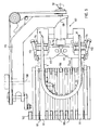
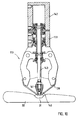
- FIG. 5 shows a top view of a molding unit.
- Their molding table is located itself in a lower end position so that the U-shaped dough strand 3 with its leg end sections with maximum depth in the sling device 107 protrudes.
- the lower end position as well as the upper end position of the molding table 101 can be marked by (not shown) limit switches, which the Activate swivel cylinder 104 (see FIG. 4) accordingly.
- the molding table 101 is with a plurality of individual conveyor strips 110, 111 running side by side realized. Two conveyor strips are at a distance from each other of the leg end sections 31 111 arranged to carry the dough strand legs with a wider support surface than the other conveyor strips 110 are provided.
- the Conveyor strips 110, 111 are designed as continuously rotating conveyor belts.
- the forming table 101 can be lowered (not shown) or raising the pivot axis 102.
- the mounting pins 112 are inserted between the conveyor strips 110, 111 by means of countersink cylinders 124 and extendable or retractable attached.
- process step e) according to FIG 1 or in the delivery position of the second mold unit 11 in the right half of the Figure 4, the retaining pins 112 are retracted or sunk to the finished Release pretzel blank 6 for transfer to the discharge device 12.
- the sling device 107 is at a smaller distance Dmin from the end edge 106 of the forming table 101, which is at its lower end position is due. Because of this, the legs of the U-shaped penetrate Dough strands 3 each have a gripping member 113 and a light barrier detection sensor 114.
- the distance Dmax between the sling device 107 and the End edge 106 of the forming table 101 is enlarged by the end edge 106 pivotal 103 upwards by actuating the swivel cylinder 104 has been granted.
- the leg ends are out of the range of Light barrier detection sensors 114 pulled out. Their resulting Output signal change leads to a control of a (not shown) Drive or closing mechanism of the gripping members 113, so that these Pinch leg ends 31 between them. If the molding table 101 with its pivoted a little further up the front end edge 106, the U-shaped Dough strand 3 somewhat stretched, which is advantageous later on the formation of a tightens, compact looping knot 52 (cf. process step d in FIG. 1).
- the sling device 107 is on a swivel yoke 115 .mu.m the above-mentioned wrap axis of rotation 109 is rotatable for executing Looping rotations 53 corresponding to method step d) in FIG. 1 are rotatably supported.
- the gripping members 113 are connected to one another via a holding frame 116 connected and so rotatable on the swivel yoke 115.
- the holding frame 116 has in particular two swivel wings 117, each with one of the gripping members 113 firmly connected and pivotable in one plane via pivot axes 118 are parallel to the plane spanned by dough strand U-legs.
- sliding cylinders 119 are also on the outer sides of the swivel blades 117 extendable plungers 120 attached.
- the detection sensors 114 are on the Sechwenkjoch fixed immovably.
- the arrangement with the gripping members 113 is used Swivel wings 117 and the sliding cylinders 119 attached to them Process step c) in FIG. 1 to produce an ⁇ dough strand 4.
- Swivel wings 117 and the sliding cylinders 119 Process step c) in FIG. 1 to produce an ⁇ dough strand 4.
- the two pivot wings 117 pivoted inwards towards each other their Sloping side sections 121 have come into abutment against each other.
- the each entrained gripping members 113 align the dough strand end sections 41 diverging outward from each other.
- the push rod 120 of the sliding cylinder 119 are extended and push the U-legs of the dough strand from the outside towards each other inside, so that an extreme between the two "Bottle neck-like" narrowed gap 122 is formed.
- the gripping members 113 are in positions for receiving a Dough strand 3 shown.
- the gripping member can be spread apart with two by pivoting ( Figure 8) and closable ( Figure 9) jaws 131. They can each be spread apart about pivot axes 132 (perpendicular to the plane of the drawing) and closable.
- a first lifting cylinder 133 preferably operated with compressed air used in a displaceable outer piston 134 linear actuating movements 135 can be granted.
- the upper area of the outer bulb 134 clasps the inner ends 136 of the jaws 131.
- the outer jaw ends 137 are of a common one Includes rubber cord 138, with bead ends 139 in the outer sides the jaw 131 is anchored. So that the rubber strand 138 for the dough strand 3 can form a receptive depression, it is also with a central one Bead branch 140 provided, preferably in a plunger 141 of a second is anchored by means of compressed air driven lifting cylinder 142.
- the gripping member after the "pick up” phase according to FIG. 8 and the "access” phase according to FIG. 9 "depositing with jaw opening” initiate.
- the second lifting cylinder 142 with the inner piston 143 actuated so that the plunger 141 is moved to the maximum.
- the end of the dough strand can be 31 press onto the middle part of the dough strand 32, as shown in FIG.
- the gripping member 113 is correspondingly left from the open position above Half in Figure 1 by about 180 ° about the folding axis 108 in the downward Position according to Figure 10 or right half in Figure 1 in the course of push-pull movements of the two mold units 10, 11 has been adjusted.
- the middle part or main part 32 of the dough strand can be stationary on the molding table 101 remain, which enables a weight-relieving loop. In addition, must there is no tearing or cutting of the ends of the dough strand.
Landscapes
- Life Sciences & Earth Sciences (AREA)
- Engineering & Computer Science (AREA)
- Food Science & Technology (AREA)
- Manufacturing And Processing Devices For Dough (AREA)
Abstract
Description
- Figur 1
- eine erfindungsgemäße Brezelschlingmaschine in der Seitenansicht nebst den zugehörigen Teigverarbeitungsschritten a) - e),
- Figur 2
- die Zuführeinrichtung gemäß Figur 1 in vergrößerter Seitenansicht,
- Fig. 2a
- eine schematische Draufsicht auf die Richteinheit
- Figur 3
- eine abgewandelte Ausbildung der Zuführeinrichtung mit Auswurforgan in entsprechender Seitenansicht,
- Figur 4
- das Drehgestell mit Formeinheiten gemäß Figur 1 in vergrösserter Seitenansicht,
- Figur 5
- eine Draufsicht auf eine Formeinheit für die Brezelschlingmaschine nach Figur 1,
- Figur 6
- eine entsprechende Draufsicht auf die Formeinheit mit angehobenem Formtisch und geschlossenen Greiforganen,
- Figur 7
- eine entsprechende Draufsicht auf die Formeinheit mit nach außen geschwenkten Greiforganen zur Bildung der Ω-Form,
- Figur 8
- das erfindungsgemäße Greiforgan in Längsseitenansicht, teilweise axial geschnitten mit geöffneten Klemmbacken,
- Figur 9
- eine entsprechende Ansicht auf das Greiforgan gemäß Figur 8 mit geschlossenen Klemmbacken und
- Figur 10
- das vorgenannte Greiforgan in entsprechender Ansicht mit geöffneten Klemmbacken und ausgefahrenem Zug- und Druckelement.
- 1
- Transport- und Förderrichtung
- 2
- Teigstrang, quer
- 3
- U-Teigstrang
- 31
- Schenkelteile
- 32
- Mittelteil
- 4
- Ω-Teigstrang
- 41
- Endabschnitte
- 5
- Schlingteigstücke
- 51
- Schlingachse
- 52
- Knoten
- 53
- Schlingdrehung
- 6
- Brezelrohling
- 61
- Umklappbewegung
- 62
- Klappachse
- 7
- Zuführeinrichtung
- 71
- Förderband
- 72
- horizontaler Abschnitt
- 73
- Ausgang
- 74
- Schrägabschnitt
- 75
- Förderrolle
- 76
- Förderrolle
- 77
- Förderrolle
- 8
- Richteinheit
- 81
- Richtrad
- 82
- Erkennungsensorik
- 83
- Drehachse
- 84
- Drehung
- 85
- Aufsetz- und Abhebebewegung/Schwenkung
- 86
- Antriebsmittel
- 87
- Schwenkplatte
- 88
- Schwenkachse
- 9
- Drehgestell
- 91
- Drehlagerung
- 92
- Drehachse
- 93
- Antriebsmotor
- 94
- Drehrichtung
- 95
- Stirnwandung
- 96
- Tragwerk
- 10
- erste Formeinheit
- 101
- Formtisch
- 102
- Schwenkachse
- 103
- Verschwenkung
- 104
- Schwenkzylinder
- 105
- Seitenwandung
- 106
- Endkante
- 107
- Schlinggerät
- 108
- Klappachse
- 109
- Drehachse
- 11
- zweite Formeinheit
- 110
- Förderstreifen
- 111
- Förderstreifen
- 112
- Haltestifte
- 113
- Greiforgan
- 114
- Erkennungsensoren
- 115
- Schwenkjoch
- 116
- Haltegestell
- 117
- Schwenkflügel
- 118
- Schwenkachse
- 119
- Schiebezylinder
- 12
- Abführeinrichtung
- 12a
- Förderband
- 120
- Stößel
- 121
- Schrägseitenabschnitte
- 122
- verengter Spalt
- 123
- Schwenkbewegung
- 131
- Klemmbacken
- 132
- Schwenkachse
- 133
- Zylinder
- 134
- Außenkolben
- 135
- Stellbewegung
- 136
- innere Klemmbacken
- 137
- äußere Klemmbackenenden
- 138
- Gummistrang
- 139
- Wulstende
- 14
- Vorformstation
- 140
- Wulstabzweigung
- 141
- Stößel
- 142
- zweiter Zylinder
- 143
- Innenkolben
- 15
- Auswurfförderband
- 151
- Förderrichtung
- 152
- Auswurfspalt
- Dmin
- Abstand
Claims (26)
- Verfahren zum maschinellen Herstellen von Brezelrohlingen (6), unter Verwendung mehrerer Brezel-Formeinheiten (10,11) die jeweils in eine Stellung zur Aufnahme eines Teigstrangs (2) von einer gemeinsamen Teigstrang-Zuführeinrichtung (7) und in eine davon entfernte Stellung zur Abgabe des geformten Brezelrohlings (6) an eine gemeinsame Abführeinrichtung (12) versetzbar sind, wobei in jeder Formeinheit (10,11) ein aufgenommener Teigstrang (3) zum Brezelrohling (6) gestaltet und an die Abführeinrichtung (12) übergeben wird, dadurch gekennzeichnet, daß zwei Formeinheiten (10,11) zueinander komplementär und/oder im Gegentakt betrieben werden, indem eine erste (10) der Formeinheiten (10,11) von der Aufnahmestellung direkt in die Abgabestellung versetzt wird, während gleichzeitig die zweite Formeinheit (11) umgekehrt zur ersten von der Abgabestellung direkt in die Aufnahmestellung versetzt wird, und dann die erste Formeinheit (10) von der Abgabestellung wieder direkt in die Aufnahmestellung versetzt wird, während gleichzeitig die zweite Formeinheit (10) umgekehrt zur ersten von der Aufnahmestellung wieder direkt in die Abgabestellung versetzt wird, wobei jeweils in einer (10) der beiden Formeinheiten (10,11) der Teigstrang (3) während des Versetzens von der Aufnahme- in die Abgabestellung zum Brezelrohling (6) gestaltet wird, und im Parallelbetrieb dazu die jeweils andere Formeinheit (11) in einen Teigstrang-Aufnahmezustand zurückversetzt wird.
- Verfahren nach Anspruch 1, dadurch gekennzeichnet, daß die erste und zweite Formeinheit (10,11) zueinander synchron verstellt werden.
- Verfahren nach einem der vorangehenden Ansprüche, dadurch gekennzeichnet, daß während der Aufnahmestellung mittels der jeweiligen Formeinheit (10,11) der Teigstrang (3) mit der Grundform etwa eines Ω (Omega) versehen wird.
- Verfahren nach einem der vorangehenden Ansprüche, dadurch gekennzeichnet, daß vor dem Verlassen der Aufnahmestellung in der jeweiligen Formeinheit (10,11) dem Teigstrang (3) eine U-Form mit zwei frei endenden Schenkeln (31) und einem diese verbindenden Mittelabschnitt (32) erteilt wird, und mit oder nach Verlassen der Aufnahmestellung durch die jeweilige Formeinheit (10,11) die Schenkelenden (31) des Teigstrangs (3) miteinander um eine erste Achse (51) zur Bildung eines Knotens (52) verschlungen, um eine zweite Achse (62) geschwenkt und spätestens zum Erreichen der Abgabestellung auf den Mittelabschnitt (32) gesetzt werden.
- Verfahren nach Anspruch 4, dadurch gekennzeichnet, daß die Bewegungen des Schlingens (53) um die erste Achse (51) und des Schwenkens (61) um die zweite Achse (62) gleichzeitig und/oder einander überlagert ausgeführt werden.
- Verfahren nach Anspruch 4 oder 5, wobei die erste und zweite Formeinheit (10,11) satellitenartig um ein gemeinsames Zentrum oder um eine gemeinsame Achse (92) bewegt werden, dadurch gekennzeichnet, daß die gemeinsame Achse (92) schräg oder senkrecht zur jeweiligen ersten SchlingAchse (51,109) und senkrecht zur jeweiligen zweiten Schwenk-Achse (62,108) gelegt wird.
- Verfahren nach einem der vorangehenden Ansprüche, dadurch gekennzeichnet, daß die erste und die zweite Formeinheit (10,11) für die Aufnahmestellung und/oder für die Abgabestellung jeweils zum selben Ort am Ausgang (73) der Zuführeinrichtung (7) oder am Eingang der Abführeinrichtung (12) bewegt werden.
- Anordnung zur maschinellen Brezelherstellung gemäß dem Verfahren nach einem der vorangehenden Ansprüche, mit mehreren, zur Verarbeitung eines Teigstrangs (3) zu einem Brezelrohling (6) ausgebildeten Formeinheiten (10,11), die auf einem gemeinsamen Verfahrgestell angeordnet und darüber jeweils zum Ausgang (73) einer Teigstrang-Zuführeinrichtung (7) oder zum Eingang einer Brezelrohling-Abführeinrichtung (12) bewegbar sind, wobei das Verfahrgestell mittels eines Antriebsmotors (93) zwischen der Zuführ- und Abführeinrichtung (7,12) geführt ist, gekennzeichnet durch eine Anordnung der Formeinheiten (10,11) auf dem Verfahrgestell derart, daß bei Verstellung einer ersten der Formeinheiten (10,11) in eine Abgabeposition unmittelbar am Eingang der Abführeinrichtung (12) gleichzeitig eine zweite der Formeinheiten (10,11) in eine Aufnahmeposition unmittelbar am Ausgang (73) der Zuführeinrichtung (7) verstellt ist.
- Anordnung nach Anspruch 8, dadurch gekennzeichnet, daß die Formeinheiten (10,11) im oder auf dem Fahrgestell im wesentlichen in einer Ebene liegend und/oder einander vorzugsweise symmetrisch, insbesondere punktsymmetrisch, gegenüberliegend angeordnet sind.
- Anordnung nach Anspruch 8 oder 9, wobei das Verfahrgestell als um eine Drehachse (92), die zwischen den Formeinheiten angeordnet ist, rotierbares Drehgestell (9) ausgebildet ist, dadurch gekennzeichnet, daß die Drehachse (92) des Drehgestells (9) vertikal und/oder senkrecht zu einer etwaigen gemeinsamen Ebene der Formeinheiten (10,11) und/oder zu einer von der jeweiligen Formeinheit (10,11) für die Teigstrang-Endabschnitte (31,41) realisierten Schling- und/oder Umklappachse (109,108) verläuft.
- Anordnung nach einem der vorangehenden Ansprüche, dadurch gekennzeichnet, daß die Zu- und Abführeinrichtungen (7,12) sowie die Formeinheiten (10,11) mit jeweils in der Aufnahme- oder Abführposition aneinander anschließenden Förderbändern (71; 110,111; 12a) realisiert sind.
- Anordnung nach einem der vorangehenden Ansprüche, dadurch gekennzeichnet, daß die Zuführeinrichtung (7) mit einer Strang-Längenmeßeinheit (81,82) und einer Strangbiegeeinheit (81) versehen ist, die zum symmetrischen Ausrichten der Teigstränge (3) gemäß einer U-Form miteinander in Wirkverbindung stehen.
- Anordnung nach Anspruch 12, gekennzeichnet durch ein zwischen der Zuführeinrichtung (7) und der jeweils an dieser anstehenden Formeinheit (10,11) angeordnetes Teigstrang-Auswerforgan (15), das zu seiner Betätigung mit der Strang-Längenmeßeinheit (81,82) gekoppelt ist.
- Zuführeinrichtung verwendet als Biege- und Längenmeßeinrichtung für die Anordnung nach Anspruch 14 oder 15, gekennzeichnet durch ein Förderband (71), auf dessen Oberfläche mit quer aufstehender Drehachse (83) ein motorisch drehbares Richtrad (81) so angeordnet und abhebbar (85) ist, daß geförderte Teigstränge (2) daran unter Erhalt einer U-Form in Anlage kommen und mit Abheben (85) des Richtrades (81) zur Weiterbeförderung freigegeben sind, und daß dem Richtrad (81) ein Winkelgeber zur Erfassung seines Drehweges (x), und dem U-förmig gebogenen Teigstrang eine Sensorik (82) zur separaten Erkennung je eines seiner beiden Enden (31) zugeordnet sind, wobei der Antriebsmotor des Richtrades (81) von einer Steuereinrichtung kontrolliert ist, die eingangsseitig mit dem Winkelgeber und der Sensorik (82) verbunden ist.
- Einrichtung nach Anspruch 14, dadurch gekennzeichnet, daß im Bereich des Richtrades (81) das Förderband (71) in Richtung zu seinem Ausgang (73) abfallend und/oder geneigt verläuft.
- Formeinheit (10,11) für das Verfahren oder die Anordnung nach einem der vorangehenden Ansprüche, mit einem Formtisch (101), der einen Halterungssattel (112) zur Auflage des Mittelabschnitts (32) U-förmiger Teigstränge (3) aufweist, und mit einem gegenüber dem Formtisch (101) drehbaren und auf den Formtisch (101) klapp- oder schwenkbaren Schlinggerät (107), das mit je einem Greiforgan (113) für darin vom Formtisch (101) aus einragende Endabschnitte (31) des U-förmigen Teigstrangs (3) versehen ist, dadurch gekennzeichnet, daß der Formtisch (101) in seinem Abstand (Dmin,Dmax) oder seiner Höhe gegenüber dem Schlingerät (107) verstellbar ausgebildet ist, und die Betätigung der Greiforgane (113) über je einem Teigstrangende (31) zugeordnete Erkennungssensoren (114) angesteuert wird, wenn diese jeweils auf das Entfernen eines der Teigstrangenden (31) im Zuge der Verstellung (103) des Abstandes (Dmin,Dmax) oder der Höhe des Formtisches (101) ansprechen.
- Formeinheit nach Anspruch 16, dadurch gekennzeichnet, daß am Formtisch (101) zu seiner Abstands- oder Höhenverstellung (103) eine Antriebseinheit (104) in Angriff gebracht ist, die von den Erkennungssensoren (114) und/oder einer Endschaltereinrichtung für eine oder mehrere Endpositionen des Formtisches (101) angesteuert und/oder abgeschaltet wird.
- Formeinheit nach Anspruch 16 oder 17, dadurch gekennzeichnet, daß zu seiner Abstands- oder Höhenverstellung (103) der Formtisch (101) an dem Verfahr- oder Drehgestell (9) oder einem sonstigen Chassis so angelenkt ist, daß durch Verschwenken (103) die dem Schlinggerät (107) zugewandte Formtischkante (106) in ihrer Höhe oder ihrem Abstand (Dmin,Dmax) zum Schlinggerät (107) verstellbar ist.
- Formeinheit nach Anspruch 18, dadurch gekennzeichnet, daß die Anlenkachse (102) des Formtisches (101) relativ zum Schlinggerät (107) so gelegt ist, daß die Schwenkbahn der Formtischkante (106) etwa tangential und/oder weitgehend parallel zur durch die Teigstrangendabschnitte (31) aufgespannten Ebene und/oder zu einer Schlingachse (109) der Teigstrangendabschnitte (31) verläuft.
- Formeinheit nach einem der vorangehenden Ansprüche, dadurch gekennzeichnet, daß das Schlinggerät (107) um eine Teigstrangenden-Schlingachse (109) drehbar auf einem Schwenkjoch (115) angeordnet ist, das gegenüber dem Verfahr- oder Drehgestell (9) oder einem sonstigen Chassis um eine Klappachse (108) so angelenkt ist, daß das Schlingerät (107) und/oder dessen Greiforgane (113) zur Oberseite des Formtisches (101) schwenk- oder klappbar ist.
- Formeinheit nach einem der vorangehenden Ansprüche, dadurch gekennzeichnet, daß die Greiforgane (113) über ein gemeinsames, um eine Teigstrangenden-Schlingachse (109) drehbares Haltegestell (116) miteinander verbunden sind.
- Formeinheit nach Anspruch 21, dadurch gekennzeichnet, daß die Greiforgane (113) am Haltegestell (116) vorzugsweise symmetrisch gegeneinander verschwenkbar in einer Schwenkebene parallel zu oder in einer von den Teigstrang-Endabschnitten (31) aufgespannten Ebene angebracht sind, so daß die Greiforgane (113) die Teigstrang-Endabschnitte (31) voneinander divergierend ausrichten können.
- Formeinheit nach Anspruch 22, dadurch gekennzeichnet, daß mit der Schwenkbewegung (123) jedes Greiforgans (113) jeweils ein Schiebeelement (119) gekoppelt ist, das einer Endabschnitt-Außenseite des U-förmigen Teigstrangs (3) zugeordnet ist, wodurch dem Teigstrang (3) eine Grundform etwa eines Ω (Omega) erteilbar ist.
- Greiforgan (113) für die Formeinheit (10,11) nach einem der vorangehenden Ansprüche, mit zwei Klemmbacken (131), die mittels einer ersten Antriebseinheit (133) gegeneinander zum Klemmen und Freigeben von Teig (31) bewegbar sind, und mit einem zwischen den Klemmbacken (131) angeordneten Druckelement (141,143), das von einer zweiten Antriebseinheit (142) ein- und ausfahrbar geführt ist dadurch gekennzeichnet, daß die freien Enden (137) der Klemmbacken (131) von einem gummielastischen Band oder Strang (138) umfaßt sind, und das Druckelement (141,143) innen am Band oder Strang (138) angreift, um als Zugelement diesen nach innen einzuziehen oder nach außen zu wölben.
- Greiforgan nach Anspruch 24, dadurch gekennzeichnet, daß das Band oder der Strang (138) mit Silikongummi realisiert ist.
- Greiforgan nach Anspruch 24 oder 25, dadurch gekennzeichnet, daß die Antriebseinheiten (133,142) jeweils mit einem zylindrischen Linearantrieb (134,143) realisiert sind, wobei ein Linearantrieb (143), vorzugsweise der der zweiten Antriebseinheit (142), von dem anderen Linearantrieb (134) umgeben und aus oder in diesen teleskopartig heraus- oder einfahrbar ist.
Applications Claiming Priority (2)
| Application Number | Priority Date | Filing Date | Title |
|---|---|---|---|
| DE19807692A DE19807692C2 (de) | 1998-02-25 | 1998-02-25 | Brezelschlingmaschine |
| DE19807692 | 1998-02-25 |
Publications (2)
| Publication Number | Publication Date |
|---|---|
| EP0938844A1 true EP0938844A1 (de) | 1999-09-01 |
| EP0938844B1 EP0938844B1 (de) | 2001-06-13 |
Family
ID=7858724
Family Applications (1)
| Application Number | Title | Priority Date | Filing Date |
|---|---|---|---|
| EP99103614A Expired - Lifetime EP0938844B1 (de) | 1998-02-25 | 1999-02-25 | Brezelschlingsystem |
Country Status (2)
| Country | Link |
|---|---|
| EP (1) | EP0938844B1 (de) |
| DE (2) | DE19807692C2 (de) |
Cited By (6)
| Publication number | Priority date | Publication date | Assignee | Title |
|---|---|---|---|---|
| WO2001060164A1 (de) * | 2000-02-17 | 2001-08-23 | Fritsch Gmbh & Co. Kg | Brezelherstellungssystem |
| DE10029171A1 (de) * | 2000-02-17 | 2001-08-23 | Fritsch A Gmbh & Co Kg | Brezelherstellungssystem |
| WO2005065458A3 (de) * | 2004-01-12 | 2005-10-20 | Fritsch Gmbh | Teigstrang-schlingsystem |
| WO2006089928A1 (de) * | 2005-02-25 | 2006-08-31 | Fritsch Gmbh | Verfahren zur herstellung von geschlungenen teigrohlingen aus teigsträngen sowie vorrichtung zur maschinellen herstellung von geschlungenen teigwaren |
| DE102006051301A1 (de) * | 2006-10-31 | 2008-05-08 | Oswald Piller | Verfahren zum Ausrichten und Formen von Teigrohlingen, insbesondere von zur Brezelherstellung vorgeformten Teigsträngen und System zur Durchführung des Verfahrens |
| EP1935246A1 (de) * | 2006-12-21 | 2008-06-25 | Fritsch GmbH | System zum Vermessen und Ausrichten von Teigsträngen in ihrer Länge und Lage |
Families Citing this family (5)
| Publication number | Priority date | Publication date | Assignee | Title |
|---|---|---|---|---|
| WO2007104801A1 (de) * | 2006-03-16 | 2007-09-20 | Fritsch Gmbh | Biege- und schlingmaschine für teigstücke |
| DE102006051300B4 (de) * | 2006-10-31 | 2008-09-11 | Oswald Piller | Vorrichtung zum Strecken oder Glätten und/oder Ausrichten von Teigrohlingen, insbesondere von zur Brezelherstellung vorgeformten Teigsträngen und Verfahren zum Betreiben der Vorrichtung |
| DE102010008024B4 (de) | 2010-02-15 | 2014-06-18 | Oswald Piller | Vorrichtung zum Strecken bzw. Glätten und/oder Ausrichten von Teigrohlingen, insbesondere von zur Brezelherstellung vorgeformten Teigsträngen und Verfahren zum Betreiben der Vorrichtung |
| DE102011050372B4 (de) | 2011-05-16 | 2017-05-18 | Oswald Piller | Vorrichtung zum Strecken und/oder Ausrichten von Teigrohlingen, insbesondere von zur Brezelherstellung vorgeformten Teigsträngen |
| DE102020126779A1 (de) | 2020-10-13 | 2022-04-14 | Fritsch Bakery Technologies GmbH & Co. KG | Teigverarbeitungsmaschine zum Bearbeiten von Produkten |
Citations (13)
| Publication number | Priority date | Publication date | Assignee | Title |
|---|---|---|---|---|
| US1669277A (en) * | 1927-03-07 | 1928-05-08 | Willis L Barthold | Pretzel-making machine |
| US1957135A (en) * | 1932-07-23 | 1934-05-01 | Horace Robertshaw | Pretzel making machine |
| US2068234A (en) * | 1933-04-04 | 1937-01-19 | Nat Biscuit Co | Machine and method for making pretzels |
| DE1288532B (de) | 1964-11-24 | 1969-02-06 | Quinlan Pretzel Company | Brezel-Formmaschine |
| DE4105254C1 (de) | 1991-02-20 | 1992-05-14 | Brezelbaeckerei Ditsch Gmbh, 6500 Mainz, De | |
| DE4411742A1 (de) * | 1994-04-06 | 1994-09-08 | Wilhelm Hepke | Brezen - Fertigungsmaschine |
| DE4432162A1 (de) | 1993-10-13 | 1995-04-20 | Haberzeth Thomas | Verfahren, Vorrichtung und Anordnung zum Formen einer Brezel |
| DE19508964A1 (de) * | 1995-03-13 | 1995-11-16 | Thomas Kraemer | Verfahren und Einrichtung zum maschinellen Formen eines Backwarenstücks aus einem Teigstrang |
| DE4441301C1 (de) | 1993-10-25 | 1996-01-18 | Oswald Piller | Vorrichtung zur Herstellung von Brezeln |
| DE4430172A1 (de) | 1994-08-25 | 1996-02-29 | Oku Automatik Otto Kurz Gmbh & | Einrichtung zur Herstellung von Brezeln |
| DE29620893U1 (de) | 1996-12-02 | 1997-01-23 | Prokon GmbH, 01109 Dresden | Brezelschlingmaschine |
| DE19721062A1 (de) * | 1996-05-22 | 1997-11-27 | Hubert Scheitenberger | Vorrichtung zur Herstellung von Rohbrezeln aus abgelängten Teigsträngen |
| DE29622420U1 (de) * | 1996-12-24 | 1998-04-23 | Müller, Walter, 85049 Ingolstadt | Brezenformmaschine |
-
1998
- 1998-02-25 DE DE19807692A patent/DE19807692C2/de not_active Expired - Lifetime
-
1999
- 1999-02-25 DE DE59900114T patent/DE59900114D1/de not_active Expired - Lifetime
- 1999-02-25 EP EP99103614A patent/EP0938844B1/de not_active Expired - Lifetime
Patent Citations (14)
| Publication number | Priority date | Publication date | Assignee | Title |
|---|---|---|---|---|
| US1669277A (en) * | 1927-03-07 | 1928-05-08 | Willis L Barthold | Pretzel-making machine |
| US1957135A (en) * | 1932-07-23 | 1934-05-01 | Horace Robertshaw | Pretzel making machine |
| US2068234A (en) * | 1933-04-04 | 1937-01-19 | Nat Biscuit Co | Machine and method for making pretzels |
| DE1288532B (de) | 1964-11-24 | 1969-02-06 | Quinlan Pretzel Company | Brezel-Formmaschine |
| DE4105254C1 (de) | 1991-02-20 | 1992-05-14 | Brezelbaeckerei Ditsch Gmbh, 6500 Mainz, De | |
| DE4432162A1 (de) | 1993-10-13 | 1995-04-20 | Haberzeth Thomas | Verfahren, Vorrichtung und Anordnung zum Formen einer Brezel |
| DE4441301C1 (de) | 1993-10-25 | 1996-01-18 | Oswald Piller | Vorrichtung zur Herstellung von Brezeln |
| DE19511409C1 (de) * | 1993-10-25 | 1996-05-09 | Oswald Piller | Vorrichtung zur Herstellung von Brezeln |
| DE4411742A1 (de) * | 1994-04-06 | 1994-09-08 | Wilhelm Hepke | Brezen - Fertigungsmaschine |
| DE4430172A1 (de) | 1994-08-25 | 1996-02-29 | Oku Automatik Otto Kurz Gmbh & | Einrichtung zur Herstellung von Brezeln |
| DE19508964A1 (de) * | 1995-03-13 | 1995-11-16 | Thomas Kraemer | Verfahren und Einrichtung zum maschinellen Formen eines Backwarenstücks aus einem Teigstrang |
| DE19721062A1 (de) * | 1996-05-22 | 1997-11-27 | Hubert Scheitenberger | Vorrichtung zur Herstellung von Rohbrezeln aus abgelängten Teigsträngen |
| DE29620893U1 (de) | 1996-12-02 | 1997-01-23 | Prokon GmbH, 01109 Dresden | Brezelschlingmaschine |
| DE29622420U1 (de) * | 1996-12-24 | 1998-04-23 | Müller, Walter, 85049 Ingolstadt | Brezenformmaschine |
Cited By (11)
| Publication number | Priority date | Publication date | Assignee | Title |
|---|---|---|---|---|
| WO2001060164A1 (de) * | 2000-02-17 | 2001-08-23 | Fritsch Gmbh & Co. Kg | Brezelherstellungssystem |
| DE10029171A1 (de) * | 2000-02-17 | 2001-08-23 | Fritsch A Gmbh & Co Kg | Brezelherstellungssystem |
| DE10029171B4 (de) * | 2000-02-17 | 2014-12-31 | Fritsch Gmbh | Brezelherstellungssystem |
| DE10029171C5 (de) * | 2000-02-17 | 2020-03-19 | Fritsch Bakery Technologies GmbH & Co. KG | Brezelherstellungssystem |
| DE10029171C9 (de) | 2000-02-17 | 2020-04-30 | Fritsch Bakery Technologies GmbH & Co. KG | Brezelherstellungssystem |
| WO2005065458A3 (de) * | 2004-01-12 | 2005-10-20 | Fritsch Gmbh | Teigstrang-schlingsystem |
| US8173191B2 (en) | 2004-01-12 | 2012-05-08 | Fritsch Gmbh | Knotting system for a dough strand |
| WO2006089928A1 (de) * | 2005-02-25 | 2006-08-31 | Fritsch Gmbh | Verfahren zur herstellung von geschlungenen teigrohlingen aus teigsträngen sowie vorrichtung zur maschinellen herstellung von geschlungenen teigwaren |
| DE102006051301A1 (de) * | 2006-10-31 | 2008-05-08 | Oswald Piller | Verfahren zum Ausrichten und Formen von Teigrohlingen, insbesondere von zur Brezelherstellung vorgeformten Teigsträngen und System zur Durchführung des Verfahrens |
| DE102006051301B4 (de) * | 2006-10-31 | 2010-04-01 | Oswald Piller | Verfahren zum Ausrichten und Formen von Teigrohlingen, insbesondere von zur Brezelherstellung vorgeformten Teigsträngen und System zur Durchführung des Verfahrens |
| EP1935246A1 (de) * | 2006-12-21 | 2008-06-25 | Fritsch GmbH | System zum Vermessen und Ausrichten von Teigsträngen in ihrer Länge und Lage |
Also Published As
| Publication number | Publication date |
|---|---|
| EP0938844B1 (de) | 2001-06-13 |
| DE59900114D1 (de) | 2001-07-19 |
| DE19807692A1 (de) | 1999-09-09 |
| DE19807692C2 (de) | 2001-04-12 |
Similar Documents
| Publication | Publication Date | Title |
|---|---|---|
| DE3742404C2 (de) | Verfahren und Vorrichtung zur Übergabe von Produkten | |
| DE102010027622B4 (de) | Vorrichtung zum Formen von Teiglingen | |
| EP0587870B1 (de) | Verfahren und vorrichtung zur maschinellen herstellung von brezeln | |
| DE3636767C2 (de) | ||
| DE4039793C2 (de) | Vorrichtung zum Biegen von Teigstücken, insbesondere Croissants | |
| EP0938844B1 (de) | Brezelschlingsystem | |
| EP0740508A1 (de) | Vorrichtung zum aufwickeln eines teigbandes | |
| DE4414001A1 (de) | Palettiermaschine | |
| WO1996004194A1 (de) | Vorrichtung zum entnehmen eines stapels von flächenähnlichen produkten aus einer sammelstelle | |
| DE2162874B2 (de) | Einrichtung zum Kleben eines Scheitelstreifens aus Kautschuk auf einen Wulstring für Luftreifen | |
| DE2558998C3 (de) | Vorrichtung zum Schneiden einer mit einem Hohlkern versehenen Wickelrolle | |
| DE60015046T2 (de) | Verfahren und vorrichtung zur übergabe von blister-verpackungen von einer schneidestation zu einer förderlinie | |
| CH648261A5 (de) | Vorrichtung zum herausloesen von mittels eines foerderers gefoerderten druckprodukten aus dem foerderstrom. | |
| DE10029171C5 (de) | Brezelherstellungssystem | |
| EP0382219A1 (de) | Verfahren zum Formen von Brezeln aus vorgefertigten Teigsträngen und Vorrichtung zur Durchführung des Verfahrens | |
| AT413067B (de) | Vorrichtung zur herstellung von brezeln aus vorgeformten teigsträngen | |
| CH689273A5 (de) | Vorrichtung zur Herstellung von Brezeln. | |
| EP0500573A1 (de) | Verfahren zum falten von teigblättern, sowie vorrichtung zur durchführung dieses verfahrens. | |
| DE4242572C1 (de) | Vorrichtung zur Herstellung von Brezeln | |
| EP1255441B1 (de) | Brezelherstellungssystem | |
| DE3205463A1 (de) | Einrichtung und verfahren zur durchlaufhandhabung von blattfoermigen gegenstaenden | |
| EP0406658A1 (de) | Vorrichtung zum zeitweilen Speichern eines Gutes | |
| EP0986306A1 (de) | Herstellungsverfahren und -vorrichtung für gewickelte teigprodukte | |
| DE1264686B (de) | Maschine zum selbsttaetigen Abtrennen und Aufwickeln von Abschnitten bestimmter Laenge von einem Wattevlies fuer Tampons od. dgl. | |
| DE19654349C2 (de) | Brezenformmaschine |
Legal Events
| Date | Code | Title | Description |
|---|---|---|---|
| PUAI | Public reference made under article 153(3) epc to a published international application that has entered the european phase |
Free format text: ORIGINAL CODE: 0009012 |
|
| AK | Designated contracting states |
Kind code of ref document: A1 Designated state(s): CH DE FR GB IT LI NL |
|
| AX | Request for extension of the european patent |
Free format text: AL;LT;LV;MK;RO;SI |
|
| 17P | Request for examination filed |
Effective date: 19990723 |
|
| 17Q | First examination report despatched |
Effective date: 19991028 |
|
| AKX | Designation fees paid |
Free format text: CH DE FR GB IT LI NL |
|
| GRAG | Despatch of communication of intention to grant |
Free format text: ORIGINAL CODE: EPIDOS AGRA |
|
| GRAG | Despatch of communication of intention to grant |
Free format text: ORIGINAL CODE: EPIDOS AGRA |
|
| GRAH | Despatch of communication of intention to grant a patent |
Free format text: ORIGINAL CODE: EPIDOS IGRA |
|
| GRAH | Despatch of communication of intention to grant a patent |
Free format text: ORIGINAL CODE: EPIDOS IGRA |
|
| GRAA | (expected) grant |
Free format text: ORIGINAL CODE: 0009210 |
|
| AK | Designated contracting states |
Kind code of ref document: B1 Designated state(s): CH DE FR GB IT LI NL |
|
| REG | Reference to a national code |
Ref country code: CH Ref legal event code: NV Representative=s name: ISLER & PEDRAZZINI AG |
|
| REF | Corresponds to: |
Ref document number: 59900114 Country of ref document: DE Date of ref document: 20010719 |
|
| ITF | It: translation for a ep patent filed | ||
| GBT | Gb: translation of ep patent filed (gb section 77(6)(a)/1977) |
Effective date: 20010906 |
|
| ET | Fr: translation filed | ||
| REG | Reference to a national code |
Ref country code: GB Ref legal event code: IF02 |
|
| PLBE | No opposition filed within time limit |
Free format text: ORIGINAL CODE: 0009261 |
|
| STAA | Information on the status of an ep patent application or granted ep patent |
Free format text: STATUS: NO OPPOSITION FILED WITHIN TIME LIMIT |
|
| 26N | No opposition filed | ||
| PG25 | Lapsed in a contracting state [announced via postgrant information from national office to epo] |
Ref country code: IT Free format text: LAPSE BECAUSE OF NON-PAYMENT OF DUE FEES Effective date: 20050225 |
|
| REG | Reference to a national code |
Ref country code: CH Ref legal event code: PCAR Free format text: ISLER & PEDRAZZINI AG;POSTFACH 1772;8027 ZUERICH (CH) |
|
| PGRI | Patent reinstated in contracting state [announced from national office to epo] |
Ref country code: IT Effective date: 20091001 |
|
| REG | Reference to a national code |
Ref country code: FR Ref legal event code: PLFP Year of fee payment: 18 |
|
| REG | Reference to a national code |
Ref country code: FR Ref legal event code: PLFP Year of fee payment: 19 |
|
| REG | Reference to a national code |
Ref country code: FR Ref legal event code: PLFP Year of fee payment: 20 |
|
| PGFP | Annual fee paid to national office [announced via postgrant information from national office to epo] |
Ref country code: NL Payment date: 20180221 Year of fee payment: 20 |
|
| PGFP | Annual fee paid to national office [announced via postgrant information from national office to epo] |
Ref country code: CH Payment date: 20180221 Year of fee payment: 20 Ref country code: GB Payment date: 20180221 Year of fee payment: 20 |
|
| PGFP | Annual fee paid to national office [announced via postgrant information from national office to epo] |
Ref country code: FR Payment date: 20180226 Year of fee payment: 20 Ref country code: IT Payment date: 20180221 Year of fee payment: 20 |
|
| PGFP | Annual fee paid to national office [announced via postgrant information from national office to epo] |
Ref country code: DE Payment date: 20180423 Year of fee payment: 20 |
|
| REG | Reference to a national code |
Ref country code: DE Ref legal event code: R071 Ref document number: 59900114 Country of ref document: DE |
|
| REG | Reference to a national code |
Ref country code: NL Ref legal event code: MK Effective date: 20190224 |
|
| REG | Reference to a national code |
Ref country code: CH Ref legal event code: PL |
|
| REG | Reference to a national code |
Ref country code: GB Ref legal event code: PE20 Expiry date: 20190224 |
|
| PG25 | Lapsed in a contracting state [announced via postgrant information from national office to epo] |
Ref country code: GB Free format text: LAPSE BECAUSE OF EXPIRATION OF PROTECTION Effective date: 20190224 |