EP0940274A2 - Device for the variation of the weight distribution on the supports of self-propelled operating machines - Google Patents
Device for the variation of the weight distribution on the supports of self-propelled operating machines Download PDFInfo
- Publication number
- EP0940274A2 EP0940274A2 EP99104440A EP99104440A EP0940274A2 EP 0940274 A2 EP0940274 A2 EP 0940274A2 EP 99104440 A EP99104440 A EP 99104440A EP 99104440 A EP99104440 A EP 99104440A EP 0940274 A2 EP0940274 A2 EP 0940274A2
- Authority
- EP
- European Patent Office
- Prior art keywords
- pressure
- chamber
- variation
- supports
- cylinders
- Prior art date
- Legal status (The legal status is an assumption and is not a legal conclusion. Google has not performed a legal analysis and makes no representation as to the accuracy of the status listed.)
- Granted
Links
- 230000004048 modification Effects 0.000 claims abstract description 5
- 238000012986 modification Methods 0.000 claims abstract description 5
- 239000003638 chemical reducing agent Substances 0.000 claims description 7
- 230000000694 effects Effects 0.000 description 4
- 239000000463 material Substances 0.000 description 4
- 239000000725 suspension Substances 0.000 description 4
- 230000003213 activating effect Effects 0.000 description 1
- 239000010426 asphalt Substances 0.000 description 1
- 239000012530 fluid Substances 0.000 description 1
- 238000004519 manufacturing process Methods 0.000 description 1
Images


Classifications
-
- E—FIXED CONSTRUCTIONS
- E01—CONSTRUCTION OF ROADS, RAILWAYS, OR BRIDGES
- E01C—CONSTRUCTION OF, OR SURFACES FOR, ROADS, SPORTS GROUNDS, OR THE LIKE; MACHINES OR AUXILIARY TOOLS FOR CONSTRUCTION OR REPAIR
- E01C23/00—Auxiliary devices or arrangements for constructing, repairing, reconditioning, or taking-up road or like surfaces
- E01C23/06—Devices or arrangements for working the finished surface; Devices for repairing or reconditioning the surface of damaged paving; Recycling in place or on the road
- E01C23/08—Devices or arrangements for working the finished surface; Devices for repairing or reconditioning the surface of damaged paving; Recycling in place or on the road for roughening or patterning; for removing the surface down to a predetermined depth high spots or material bonded to the surface, e.g. markings; for maintaining earth roads, clay courts or like surfaces by means of surface working tools, e.g. scarifiers, levelling blades
- E01C23/085—Devices or arrangements for working the finished surface; Devices for repairing or reconditioning the surface of damaged paving; Recycling in place or on the road for roughening or patterning; for removing the surface down to a predetermined depth high spots or material bonded to the surface, e.g. markings; for maintaining earth roads, clay courts or like surfaces by means of surface working tools, e.g. scarifiers, levelling blades using power-driven tools, e.g. vibratory tools
- E01C23/088—Rotary tools, e.g. milling drums
-
- B—PERFORMING OPERATIONS; TRANSPORTING
- B60—VEHICLES IN GENERAL
- B60G—VEHICLE SUSPENSION ARRANGEMENTS
- B60G21/00—Interconnection systems for two or more resiliently-suspended wheels, e.g. for stabilising a vehicle body with respect to acceleration, deceleration or centrifugal forces
- B60G21/02—Interconnection systems for two or more resiliently-suspended wheels, e.g. for stabilising a vehicle body with respect to acceleration, deceleration or centrifugal forces permanently interconnected
- B60G21/06—Interconnection systems for two or more resiliently-suspended wheels, e.g. for stabilising a vehicle body with respect to acceleration, deceleration or centrifugal forces permanently interconnected fluid
- B60G21/073—Interconnection systems for two or more resiliently-suspended wheels, e.g. for stabilising a vehicle body with respect to acceleration, deceleration or centrifugal forces permanently interconnected fluid between wheels on the same axle but on different sides of the vehicle, i.e. the left and right wheel suspensions being interconnected
-
- B—PERFORMING OPERATIONS; TRANSPORTING
- B60—VEHICLES IN GENERAL
- B60G—VEHICLE SUSPENSION ARRANGEMENTS
- B60G21/00—Interconnection systems for two or more resiliently-suspended wheels, e.g. for stabilising a vehicle body with respect to acceleration, deceleration or centrifugal forces
- B60G21/10—Interconnection systems for two or more resiliently-suspended wheels, e.g. for stabilising a vehicle body with respect to acceleration, deceleration or centrifugal forces not permanently interconnected, e.g. operative only on acceleration, only on deceleration or only at off-straight position of steering
- B60G21/106—Interconnection systems for two or more resiliently-suspended wheels, e.g. for stabilising a vehicle body with respect to acceleration, deceleration or centrifugal forces not permanently interconnected, e.g. operative only on acceleration, only on deceleration or only at off-straight position of steering transversally
-
- B—PERFORMING OPERATIONS; TRANSPORTING
- B60—VEHICLES IN GENERAL
- B60G—VEHICLE SUSPENSION ARRANGEMENTS
- B60G2202/00—Indexing codes relating to the type of spring, damper or actuator
- B60G2202/40—Type of actuator
- B60G2202/41—Fluid actuator
- B60G2202/413—Hydraulic actuator
-
- B—PERFORMING OPERATIONS; TRANSPORTING
- B60—VEHICLES IN GENERAL
- B60G—VEHICLE SUSPENSION ARRANGEMENTS
- B60G2202/00—Indexing codes relating to the type of spring, damper or actuator
- B60G2202/40—Type of actuator
- B60G2202/41—Fluid actuator
- B60G2202/414—Fluid actuator using electrohydraulic valves
-
- B—PERFORMING OPERATIONS; TRANSPORTING
- B60—VEHICLES IN GENERAL
- B60G—VEHICLE SUSPENSION ARRANGEMENTS
- B60G2204/00—Indexing codes related to suspensions per se or to auxiliary parts
- B60G2204/80—Interactive suspensions; arrangement affecting more than one suspension unit
- B60G2204/82—Interactive suspensions; arrangement affecting more than one suspension unit left and right unit on same axle
-
- B—PERFORMING OPERATIONS; TRANSPORTING
- B60—VEHICLES IN GENERAL
- B60G—VEHICLE SUSPENSION ARRANGEMENTS
- B60G2204/00—Indexing codes related to suspensions per se or to auxiliary parts
- B60G2204/80—Interactive suspensions; arrangement affecting more than one suspension unit
- B60G2204/83—Type of interconnection
- B60G2204/8304—Type of interconnection using a fluid
-
- B—PERFORMING OPERATIONS; TRANSPORTING
- B60—VEHICLES IN GENERAL
- B60G—VEHICLE SUSPENSION ARRANGEMENTS
- B60G2300/00—Indexing codes relating to the type of vehicle
- B60G2300/08—Agricultural vehicles
- B60G2300/083—Boom carrying vehicles, e.g. for crop spraying
-
- B—PERFORMING OPERATIONS; TRANSPORTING
- B60—VEHICLES IN GENERAL
- B60G—VEHICLE SUSPENSION ARRANGEMENTS
- B60G2300/00—Indexing codes relating to the type of vehicle
- B60G2300/09—Construction vehicles, e.g. graders, excavators
-
- B—PERFORMING OPERATIONS; TRANSPORTING
- B60—VEHICLES IN GENERAL
- B60G—VEHICLE SUSPENSION ARRANGEMENTS
- B60G2300/00—Indexing codes relating to the type of vehicle
- B60G2300/32—Track vehicles
-
- B—PERFORMING OPERATIONS; TRANSPORTING
- B60—VEHICLES IN GENERAL
- B60G—VEHICLE SUSPENSION ARRANGEMENTS
- B60G2400/00—Indexing codes relating to detected, measured or calculated conditions or factors
- B60G2400/60—Load
- B60G2400/61—Load distribution
-
- B—PERFORMING OPERATIONS; TRANSPORTING
- B60—VEHICLES IN GENERAL
- B60G—VEHICLE SUSPENSION ARRANGEMENTS
- B60G2400/00—Indexing codes relating to detected, measured or calculated conditions or factors
- B60G2400/60—Load
- B60G2400/63—Location of the center of gravity
-
- B—PERFORMING OPERATIONS; TRANSPORTING
- B60—VEHICLES IN GENERAL
- B60G—VEHICLE SUSPENSION ARRANGEMENTS
- B60G2800/00—Indexing codes relating to the type of movement or to the condition of the vehicle and to the end result to be achieved by the control action
- B60G2800/01—Attitude or posture control
- B60G2800/012—Rolling condition
-
- B—PERFORMING OPERATIONS; TRANSPORTING
- B60—VEHICLES IN GENERAL
- B60G—VEHICLE SUSPENSION ARRANGEMENTS
- B60G2800/00—Indexing codes relating to the type of movement or to the condition of the vehicle and to the end result to be achieved by the control action
- B60G2800/01—Attitude or posture control
- B60G2800/019—Inclination due to load distribution or road gradient
- B60G2800/0194—Inclination due to load distribution or road gradient transversal with regard to vehicle
Definitions
- the invention concerns a device for the variation of the weight distribution on the supports of self-propelled operating machines, especially of machines used for road works.
- the conveyor belt of the removed material which is an important part of the machine, shifts in odre to load the removed material on the lorry. Since the weight of the material is added to the weight of the belt, it is clear that the machine barycenter can be exposed to cosiderable shifts according to the angle relaized by the belt with respect to the longitudinal axis of the machine.
- barycenter shifting can be observed in machines, still suited for road works, having projecting wheels that, when required, can be reentered in order to follow the road narrowing or in order not to cross fixed obstacles. In this case too the barycenter of the machine shifts.
- wheels will be used in the description, meaning both the wheels and the “tracks”.
- a support trianlge is realized where two vertex correspond to the front wheels supports and the other vertex corresponds to the intermediate point of the line joining the two contact parts on the ground of the back wheels connected hydraulically.
- the barycenter of the operating machines Since as it has been said in some cases the barycenter of the operating machines is exposed to shifts during the operativeness and since it is necessary that the machines work safely, the barycenter of the machine has to be necessarily inside the support triangle in order to avoid the upsetting of the manufactiring machine. That is why it is necessary to modify the configuration of the support triangle of the machines so that, even in the case of shift of considerable weights on the supports, the barycenter of the operating machine is included inside this triangle.
- the main aim of thr present invention is therefore that of realizing a device for the variation of the weght distribution on the front or back supports connected hydraulically so that such a variation has the effect of modifying the supporting triangle in order to make the barycenter be always inside said trianlge.
- Another aim that is wanted to be achieved is that the variation of the supporting triangle can be made automatic according to the movements of the variation of the weight distribution of the operating machine.
- a device for the variation of the weight on the supports of self-propelled operating machines especially for road works
- said machines comprise a body insisting on wheels or tracks by hydraulic suspensions
- said device characterizing in that at least one couple of hydraulic cylinders relative to the back (or front) supports are double-acting cylinders, each one having a first chamber connected hydraulically to the corresponding first chamber of the other homologus support, each second chamber of said cylinders being selectively connected through at least one electrovalve to an external source of hydraulic pressure such that the reaction thrust furnished by the respective hydraulic piston is proportional to the difference of the reaction force between said cylinders realizing the modification of the supporting ideal triangle of the operating machine.
- the variation of pressure in the second chamber of one of the two double-effect cylinders is obtained by a source of external pressure connected to said second pressure chamber through a pressure reducer. Further, the exit pressure from the reducer can be varied to give a pressure different according to the request and therefore to modify the supporting triangle of the machine according to what it is believed as necessary.
- the device implies that also the pressure given by the external source is distributed by a double way electrovalve which maintains the pressure discharged in both of the second chambers, when the electro valve is in the rest position and selectively connects one or the other chamber of each cylinder by request.
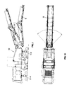
- an operating machine e.g. a scarifier machine indicated by 10
- the scarifier machine has also a movable belt 5, which can move 40-45° from the longitudinal line of the machine.
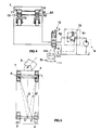
- the back supports of the tracks 3 and 4 are connected to the machine through double-effect cylinders 7 and 8 respectively.
- the cylinder 7 has a first superior chamber 71 and a second inferior chamber 72
- the cylinder 8 has a first superior chamber 81 and a second superior chamber 82.
- the piston 73 for the cylinder 7 and 83 for the cylinder 8 divides the superior and inferior chambers.
- the rod 74 of the piston 73 is connected to the support of the track 3 and the rod 84 of the piston 83 is connected to the support of the track 4.
- the superior chambers 71 and 81 are hydraulically connected through the pipeline 78 so that, lacking the pressure in the second chambers 72 and 82 respectively, in the first chambers 71 and 81 there is a fluid at a certain and always equal pressure. Therefore, being the pressures in the two chambers equal, as an effect of the connect through the pipeline 78, the pistons 73 and 83 always support a insisting on the two wheels independently by the distribution of the weights on the operating machine and independently by the position on the barycenter.
- each track 3 and 4 and therefore each piston connected to it 73 and 83 supports a weight of P/2.
- the barycenter G is internal relative to the supporting triangle A, B, C.
- the electrical gearcase 11 collects the signal 51 indicating the rotation degrees of the conveyor belt and transmits a signal 110 to the electrovalve 12 and a signal 111 to the pressure reducer 13.
- the pressure reducer 13 connected to the hydraulical gearcase 9 and to the pressure source through a pipeline 91, reduces the pressure in accordance with the signal 111 emitted by the gearcase 11 and such pressure reduced passes through the pipeline 92 and arrives to the electrovalve 12.
- Such an electrovalve being energized by the signal 110, is open in the position controlled by the switch X and permits the pressurized oil to arrive to the second chamber 72 of the cylinder 7.
- the figg. 6 and 7 show the same behaviour of the device of the invention when the conveyor belt of the operating machine is oriented in the opposite direction.
- the sensor located on the belt will emit a signal 52 which arrives to the operating gearcase 11 and such gearcase 11 emits a signal 112 activating the switch Y instead of the switch X of the electrovalve 12, while the pressure variation 13 is arranged on an opening in accordance with the signal 113 received by the gearcase to give a pressure P1 different from the pressure P requested before.
- the device of the invention can be applied also on machines different from the example.
- it can be applied on machines with wheels projecting from the profile of the machine and having the chance of being removed in particular conditions.
- the modification of the distance of the wheels implies a modification of the supporting triangle and therefore the need to make such supporting triangle do possible movements of the machine barycenter, which is possible if the device of the invention is applied to such shapes of machines.
Landscapes
- Engineering & Computer Science (AREA)
- Mechanical Engineering (AREA)
- Mining & Mineral Resources (AREA)
- Architecture (AREA)
- Civil Engineering (AREA)
- Structural Engineering (AREA)
- Vehicle Body Suspensions (AREA)
- Road Paving Machines (AREA)
- Harvester Elements (AREA)
- Automatic Assembly (AREA)
- Platform Screen Doors And Railroad Systems (AREA)
- Control Of Position, Course, Altitude, Or Attitude Of Moving Bodies (AREA)
- Road Repair (AREA)
Abstract
Description
- figg. 1 and 1a show, in view and plan view respectively, an operating machine for road works whose manufacture implies the removal of the barycenter during the work;
- fig. 2 show a scheme of the device of the invention in the rest position;
- fig. 3 shows the supporting triangle when the device of fig. 2 is ineffective;
- fig. 4 shows the scheme of the device of the invention with a cylinder submitted to a variation of pressure;
- fig. 5 shows the consequent variation of the supporting triangle;
- fig. 6 shows the scheme of the device of the invention with another cylinder submitted to variations of pressure;
- fig. 7 shows the variation of the supporting triangle relative to the device of fig. 6.
Claims (4)
- Device for the variation of the weight distribution on the supports of self-propelled operating machines, especially for road works, characterized in that at least one couple of hydraulic cylinders (7,8) relative to the back (3,4) or front (2,3) supports are double-acting cylinders each one having a first chamber (71,81) connected hydraulically to the corresponding chambers of the other homologous support, each second chamber (72,82) of said cylinder being selectively connected through at least one electrovalve (12) to a external source (9) of hydraulic pressure such that the reaction thrust furnished by the respective hydraulic piston (73,83) is proportional to the difference between the pressures of said first and of said second chamber, the difference of the reaction force between said cylinders realizing the modification of the supporting triangle of the operating machine.
- Device according to claim 1) characterized in that the selection relative to the connection of each said chamber (72,82) to said pressure source (9) is made through a two-way electrovalve (12) whose quiescent position keeps the pressure of each said second chamber of each said cylinder discharged, said electrovalve being driven by signals (110,111) emitted by a check gearcase (11) which is reached by signals (51, 52) connected to the variation of the barycenter configuration of the operating machine.
- Device according to claim 1) or 2) characterized in that between the pressure source (9) feeding the second chambers of the cylinders and the valve (13) distributing such pressure there is a pressure reducer suitable to change the ingoing pressure.
- Device according to claim 3) characterized in that the variation of the pressure reducer is driven by signals (111, 113) emitted by a check electric gearcase (11) which is reached by signals (51, 52) corresponding to the variation of the barycenter configuration of the operating machine.
Applications Claiming Priority (2)
| Application Number | Priority Date | Filing Date | Title |
|---|---|---|---|
| IT98VI000044A ITVI980044A1 (en) | 1998-03-06 | 1998-03-06 | DEVICE FOR VARIATION OF WEIGHT DISTRIBUTION ON THE SUPPORTS OF SELF-PROPELLED OPERATING MACHINES |
| ITVI980044 | 1998-03-06 |
Publications (3)
| Publication Number | Publication Date |
|---|---|
| EP0940274A2 true EP0940274A2 (en) | 1999-09-08 |
| EP0940274A3 EP0940274A3 (en) | 1999-11-10 |
| EP0940274B1 EP0940274B1 (en) | 2006-05-03 |
Family
ID=11426614
Family Applications (1)
| Application Number | Title | Priority Date | Filing Date |
|---|---|---|---|
| EP99104440A Expired - Lifetime EP0940274B1 (en) | 1998-03-06 | 1999-03-05 | Device for the variation of the weight distribution on the supports of self-propelled operating machines |
Country Status (4)
| Country | Link |
|---|---|
| EP (1) | EP0940274B1 (en) |
| AT (1) | ATE325002T1 (en) |
| DE (1) | DE69931098T2 (en) |
| IT (1) | ITVI980044A1 (en) |
Cited By (7)
| Publication number | Priority date | Publication date | Assignee | Title |
|---|---|---|---|---|
| EP1167626A1 (en) * | 2000-06-27 | 2002-01-02 | WIRTGEN GmbH | Construction machine for treating surfaces |
| WO2006094795A1 (en) | 2005-03-10 | 2006-09-14 | Wirtgen Gmbh | Road-building machine |
| US7909341B2 (en) * | 2006-05-29 | 2011-03-22 | Nederiandse Organisatie Voor Toegepast-natuurwetenschappelijk Onderzoek TNO | Suspension system for a vehicle |
| CN105239496A (en) * | 2015-11-09 | 2016-01-13 | 戴纳派克(中国)压实摊铺设备有限公司 | Frame, milling machine and milling machine gravity center adjusting method |
| WO2018115098A1 (en) * | 2016-12-22 | 2018-06-28 | Volvo Construction Equipment Ab | Paver and method for operating a paver |
| US11795664B2 (en) | 2021-02-16 | 2023-10-24 | Caterpillar Paving Products, Inc. | Four-legged construction machine having slope stability system with locking valves |
| US11932327B2 (en) | 2021-02-16 | 2024-03-19 | Caterpillar Paving Products Inc. | Four-legged construction machine having slope stability system with relief valves |
Families Citing this family (2)
| Publication number | Priority date | Publication date | Assignee | Title |
|---|---|---|---|---|
| DE102013010298A1 (en) | 2013-06-19 | 2014-12-24 | Bomag Gmbh | Construction machine, in particular road milling machine, and method for compensating for uneven floors for such a construction machine |
| DE102014019168A1 (en) | 2014-12-19 | 2016-06-23 | Bomag Gmbh | CONSTRUCTION MACHINE, PARTICULARLY ROAD TERMINAL, AND METHOD FOR COMPENSATING FLOOR INFLUENCE FOR SUCH A CONSTRUCTION MACHINE |
Family Cites Families (8)
| Publication number | Priority date | Publication date | Assignee | Title |
|---|---|---|---|---|
| US2914338A (en) * | 1956-06-25 | 1959-11-24 | Ralph H Kress | Equalized vehicle fluid suspension means |
| DE3233046C2 (en) * | 1982-09-06 | 1985-12-12 | Heilmeier & Weinlein Fabrik für Oel-Hydraulik GmbH & Co KG, 8000 München | Hydraulic control device |
| DE3783557T2 (en) * | 1986-10-24 | 1993-05-13 | Mazda Motor | VEHICLE SUSPENSION SYSTEM WITH VARIABLE SUSPENSION CHARACTERISTICS. |
| JP2528964B2 (en) * | 1989-03-27 | 1996-08-28 | 日産自動車株式会社 | Active suspension |
| US5219181A (en) * | 1989-08-23 | 1993-06-15 | Tlc Suspension | Anti-roll system with tilt limitation |
| GB2291018A (en) * | 1994-07-15 | 1996-01-17 | New Holland Nv | Utility vehicle suspensions |
| DE19521747A1 (en) * | 1995-06-14 | 1996-12-19 | Bayerische Motoren Werke Ag | Combined roll stabilisation and levelling system for vehicle chassis |
| GB2309014A (en) * | 1996-01-13 | 1997-07-16 | New Holland Nv | Utility vehicle suspension having controllably fixed or oscillating axles |
-
1998
- 1998-03-06 IT IT98VI000044A patent/ITVI980044A1/en unknown
-
1999
- 1999-03-05 DE DE69931098T patent/DE69931098T2/en not_active Expired - Lifetime
- 1999-03-05 EP EP99104440A patent/EP0940274B1/en not_active Expired - Lifetime
- 1999-03-05 AT AT99104440T patent/ATE325002T1/en not_active IP Right Cessation
Non-Patent Citations (1)
| Title |
|---|
| None |
Cited By (19)
| Publication number | Priority date | Publication date | Assignee | Title |
|---|---|---|---|---|
| US9624628B2 (en) | 2000-06-27 | 2017-04-18 | Wirtgen Gmbh | Auxiliary drive |
| EP1167626A1 (en) * | 2000-06-27 | 2002-01-02 | WIRTGEN GmbH | Construction machine for treating surfaces |
| US8807662B2 (en) | 2000-06-27 | 2014-08-19 | Wirtgen Gmbh | Auxiliary drive |
| US7922255B2 (en) | 2000-06-27 | 2011-04-12 | Wirtgen Gmbh | Auxiliary drive |
| US8167378B2 (en) | 2000-06-27 | 2012-05-01 | Wirtgen Gmbh | Auxiliary drive |
| US8480181B2 (en) | 2000-06-27 | 2013-07-09 | Wirtgen Gmbh | Auxiliary drive |
| US7901010B2 (en) | 2000-06-27 | 2011-03-08 | Wirtgen Gmbh | Movable seats |
| US9512576B2 (en) | 2000-06-27 | 2016-12-06 | Wirtgen Gmbh | Auxiliary drive |
| US7828309B2 (en) | 2005-03-10 | 2010-11-09 | Wirtgen Gmbh | Road-building machine |
| US8118316B2 (en) | 2005-03-10 | 2012-02-21 | Wirtgen Gmbh | Operational methods for a road-building machine |
| WO2006094795A1 (en) | 2005-03-10 | 2006-09-14 | Wirtgen Gmbh | Road-building machine |
| US7909341B2 (en) * | 2006-05-29 | 2011-03-22 | Nederiandse Organisatie Voor Toegepast-natuurwetenschappelijk Onderzoek TNO | Suspension system for a vehicle |
| CN105239496A (en) * | 2015-11-09 | 2016-01-13 | 戴纳派克(中国)压实摊铺设备有限公司 | Frame, milling machine and milling machine gravity center adjusting method |
| WO2018115098A1 (en) * | 2016-12-22 | 2018-06-28 | Volvo Construction Equipment Ab | Paver and method for operating a paver |
| CN110036155A (en) * | 2016-12-22 | 2019-07-19 | 沃尔沃建筑设备公司 | Paver and method for operating paver |
| US10961667B2 (en) | 2016-12-22 | 2021-03-30 | Volvo Construction Equipment Ab | Paver and method for operating a paver |
| CN110036155B (en) * | 2016-12-22 | 2022-01-11 | 沃尔沃建筑设备公司 | Paver and method for operating a paver |
| US11795664B2 (en) | 2021-02-16 | 2023-10-24 | Caterpillar Paving Products, Inc. | Four-legged construction machine having slope stability system with locking valves |
| US11932327B2 (en) | 2021-02-16 | 2024-03-19 | Caterpillar Paving Products Inc. | Four-legged construction machine having slope stability system with relief valves |
Also Published As
| Publication number | Publication date |
|---|---|
| ITVI980044A1 (en) | 1999-09-06 |
| DE69931098D1 (en) | 2006-06-08 |
| EP0940274B1 (en) | 2006-05-03 |
| DE69931098T2 (en) | 2007-04-05 |
| ATE325002T1 (en) | 2006-06-15 |
| EP0940274A3 (en) | 1999-11-10 |
Similar Documents
| Publication | Publication Date | Title |
|---|---|---|
| EP0940274A2 (en) | Device for the variation of the weight distribution on the supports of self-propelled operating machines | |
| CN1781748B (en) | Vehicle suspension system | |
| US20090014230A1 (en) | On-demand electro-hydraulic steering system | |
| JPH0868070A (en) | Ground-surface changing tool control system | |
| EP0926354A3 (en) | Solenoid-controlled pilot-operated three-position switching valve | |
| FI117795B (en) | Articulated vehicle stabilization | |
| US20220001713A1 (en) | Mobile working machine and method for stable operation of same | |
| EP1028044B1 (en) | Dual brake valve for a steering assist system | |
| US4211079A (en) | Positive neutral control for hydrostatic transmission | |
| US4455035A (en) | Anti-jackknifing device with friction brake for articulated motor vehicle | |
| CA1270864A (en) | Suspension system for a bogie vehicle | |
| CA1142976A (en) | Method and device for articulated vehicles to obtain narrow turning radiuses | |
| DE59709985D1 (en) | DIRECTIONAL VALVE FOR LOAD-INDEPENDENT CONTROL OF A HYDRAULIC CONSUMER REGARDING DIRECTION AND SPEED | |
| NZ195347A (en) | Rotary earth excavator:cutting head & conveyor ramp approach limit device | |
| DE3801267A1 (en) | VEHICLE BRAKE SYSTEM | |
| RU2208095C1 (en) | Bucket hydraulic slewing drive of single-bucket machine | |
| SU1406310A1 (en) | Bulldozer unit | |
| SU1455798A1 (en) | Device for controlling vehicle hydraulic drive | |
| SU1134455A1 (en) | Hydraulic system for controlling steering of track vehicle | |
| JPH088804B2 (en) | Steering device for agricultural work vehicle | |
| EP4045822B1 (en) | A clutch engaging arrangement | |
| SU1752213A1 (en) | Device for coupling vehicle to soil- cultivating implement | |
| SU1682483A1 (en) | Single-bucket loader | |
| SU1079475A1 (en) | Body stabilizing system for a vehicle with balance-beam wheel suspension | |
| RU2381479C1 (en) | Device to automatically and continuously adjust toe-in in motion |
Legal Events
| Date | Code | Title | Description |
|---|---|---|---|
| PUAI | Public reference made under article 153(3) epc to a published international application that has entered the european phase |
Free format text: ORIGINAL CODE: 0009012 |
|
| AK | Designated contracting states |
Kind code of ref document: A2 Designated state(s): AT BE CH DE DK ES FI FR GB GR IT LI LU NL PT SE |
|
| AX | Request for extension of the european patent |
Free format text: AL;LT;LV;MK;RO;SI |
|
| PUAL | Search report despatched |
Free format text: ORIGINAL CODE: 0009013 |
|
| AK | Designated contracting states |
Kind code of ref document: A3 Designated state(s): AT BE CH CY DE DK ES FI FR GB GR IE IT LI LU MC NL PT SE |
|
| AX | Request for extension of the european patent |
Free format text: AL;LT;LV;MK;RO;SI |
|
| 17P | Request for examination filed |
Effective date: 20000510 |
|
| AKX | Designation fees paid |
Free format text: AT BE CH DE DK ES FI FR GB GR IT LI LU NL PT SE |
|
| 17Q | First examination report despatched |
Effective date: 20020320 |
|
| GRAP | Despatch of communication of intention to grant a patent |
Free format text: ORIGINAL CODE: EPIDOSNIGR1 |
|
| GRAS | Grant fee paid |
Free format text: ORIGINAL CODE: EPIDOSNIGR3 |
|
| GRAA | (expected) grant |
Free format text: ORIGINAL CODE: 0009210 |
|
| RAP1 | Party data changed (applicant data changed or rights of an application transferred) |
Owner name: CATERPILLAR PAVING PRODUCTS INC. |
|
| AK | Designated contracting states |
Kind code of ref document: B1 Designated state(s): AT BE CH DE DK ES FI FR GB GR IT LI LU NL PT SE |
|
| PG25 | Lapsed in a contracting state [announced via postgrant information from national office to epo] |
Ref country code: NL Free format text: LAPSE BECAUSE OF FAILURE TO SUBMIT A TRANSLATION OF THE DESCRIPTION OR TO PAY THE FEE WITHIN THE PRESCRIBED TIME-LIMIT Effective date: 20060503 Ref country code: LI Free format text: LAPSE BECAUSE OF FAILURE TO SUBMIT A TRANSLATION OF THE DESCRIPTION OR TO PAY THE FEE WITHIN THE PRESCRIBED TIME-LIMIT Effective date: 20060503 Ref country code: IT Free format text: LAPSE BECAUSE OF FAILURE TO SUBMIT A TRANSLATION OF THE DESCRIPTION OR TO PAY THE FEE WITHIN THE PRESCRIBED TIME-LIMIT;WARNING: LAPSES OF ITALIAN PATENTS WITH EFFECTIVE DATE BEFORE 2007 MAY HAVE OCCURRED AT ANY TIME BEFORE 2007. THE CORRECT EFFECTIVE DATE MAY BE DIFFERENT FROM THE ONE RECORDED. Effective date: 20060503 Ref country code: FI Free format text: LAPSE BECAUSE OF FAILURE TO SUBMIT A TRANSLATION OF THE DESCRIPTION OR TO PAY THE FEE WITHIN THE PRESCRIBED TIME-LIMIT Effective date: 20060503 Ref country code: CH Free format text: LAPSE BECAUSE OF FAILURE TO SUBMIT A TRANSLATION OF THE DESCRIPTION OR TO PAY THE FEE WITHIN THE PRESCRIBED TIME-LIMIT Effective date: 20060503 Ref country code: BE Free format text: LAPSE BECAUSE OF FAILURE TO SUBMIT A TRANSLATION OF THE DESCRIPTION OR TO PAY THE FEE WITHIN THE PRESCRIBED TIME-LIMIT Effective date: 20060503 Ref country code: AT Free format text: LAPSE BECAUSE OF FAILURE TO SUBMIT A TRANSLATION OF THE DESCRIPTION OR TO PAY THE FEE WITHIN THE PRESCRIBED TIME-LIMIT Effective date: 20060503 |
|
| REG | Reference to a national code |
Ref country code: GB Ref legal event code: FG4D |
|
| REG | Reference to a national code |
Ref country code: CH Ref legal event code: EP |
|
| REF | Corresponds to: |
Ref document number: 69931098 Country of ref document: DE Date of ref document: 20060608 Kind code of ref document: P |
|
| PG25 | Lapsed in a contracting state [announced via postgrant information from national office to epo] |
Ref country code: SE Free format text: LAPSE BECAUSE OF FAILURE TO SUBMIT A TRANSLATION OF THE DESCRIPTION OR TO PAY THE FEE WITHIN THE PRESCRIBED TIME-LIMIT Effective date: 20060803 Ref country code: DK Free format text: LAPSE BECAUSE OF FAILURE TO SUBMIT A TRANSLATION OF THE DESCRIPTION OR TO PAY THE FEE WITHIN THE PRESCRIBED TIME-LIMIT Effective date: 20060803 |
|
| PG25 | Lapsed in a contracting state [announced via postgrant information from national office to epo] |
Ref country code: ES Free format text: LAPSE BECAUSE OF FAILURE TO SUBMIT A TRANSLATION OF THE DESCRIPTION OR TO PAY THE FEE WITHIN THE PRESCRIBED TIME-LIMIT Effective date: 20060814 |
|
| PG25 | Lapsed in a contracting state [announced via postgrant information from national office to epo] |
Ref country code: PT Free format text: LAPSE BECAUSE OF FAILURE TO SUBMIT A TRANSLATION OF THE DESCRIPTION OR TO PAY THE FEE WITHIN THE PRESCRIBED TIME-LIMIT Effective date: 20061003 |
|
| NLV1 | Nl: lapsed or annulled due to failure to fulfill the requirements of art. 29p and 29m of the patents act | ||
| ET | Fr: translation filed | ||
| REG | Reference to a national code |
Ref country code: CH Ref legal event code: PL |
|
| PLBE | No opposition filed within time limit |
Free format text: ORIGINAL CODE: 0009261 |
|
| STAA | Information on the status of an ep patent application or granted ep patent |
Free format text: STATUS: NO OPPOSITION FILED WITHIN TIME LIMIT |
|
| 26N | No opposition filed |
Effective date: 20070206 |
|
| GBPC | Gb: european patent ceased through non-payment of renewal fee |
Effective date: 20070305 |
|
| PG25 | Lapsed in a contracting state [announced via postgrant information from national office to epo] |
Ref country code: GR Free format text: LAPSE BECAUSE OF FAILURE TO SUBMIT A TRANSLATION OF THE DESCRIPTION OR TO PAY THE FEE WITHIN THE PRESCRIBED TIME-LIMIT Effective date: 20060804 Ref country code: GB Free format text: LAPSE BECAUSE OF NON-PAYMENT OF DUE FEES Effective date: 20070305 |
|
| PG25 | Lapsed in a contracting state [announced via postgrant information from national office to epo] |
Ref country code: LU Free format text: LAPSE BECAUSE OF NON-PAYMENT OF DUE FEES Effective date: 20070305 |
|
| PGFP | Annual fee paid to national office [announced via postgrant information from national office to epo] |
Ref country code: FR Payment date: 20130315 Year of fee payment: 15 |
|
| REG | Reference to a national code |
Ref country code: FR Ref legal event code: ST Effective date: 20141128 |
|
| PG25 | Lapsed in a contracting state [announced via postgrant information from national office to epo] |
Ref country code: FR Free format text: LAPSE BECAUSE OF NON-PAYMENT OF DUE FEES Effective date: 20140331 |
|
| PGFP | Annual fee paid to national office [announced via postgrant information from national office to epo] |
Ref country code: IT Payment date: 20150316 Year of fee payment: 17 |
|
| PGFP | Annual fee paid to national office [announced via postgrant information from national office to epo] |
Ref country code: DE Payment date: 20150331 Year of fee payment: 17 |
|
| REG | Reference to a national code |
Ref country code: DE Ref legal event code: R119 Ref document number: 69931098 Country of ref document: DE |
|
| PG25 | Lapsed in a contracting state [announced via postgrant information from national office to epo] |
Ref country code: DE Free format text: LAPSE BECAUSE OF NON-PAYMENT OF DUE FEES Effective date: 20161001 |
|
| PG25 | Lapsed in a contracting state [announced via postgrant information from national office to epo] |
Ref country code: IT Free format text: LAPSE BECAUSE OF NON-PAYMENT OF DUE FEES Effective date: 20160305 |